Week 12:Project 2-Meshing of Rear Wheel Holder challenge
AIM:
To mesh the component given below and assign thickness, with below-mentioned quality criteria
Target Element Length = 5 Units
| S.N | Quality Criteria | Value |
| 1 | Aspect Ratio | 5 |
| 2 | Skewness | 45 |
| 3 | Warping | 15 |
| 4 | Taper | 0.5 |
| 5 | Min. Length | 2 Units |
| 6 | Max. Length | 8 Units |
| 7 | Min angle Quad | 45 |
| 8 | Max angle Quad | 135 |
| 9 | Min angle Tria | 20 |
| 10 | Max angle Tria | 120 |
| 10 | Tria % | 10 |
The Component:
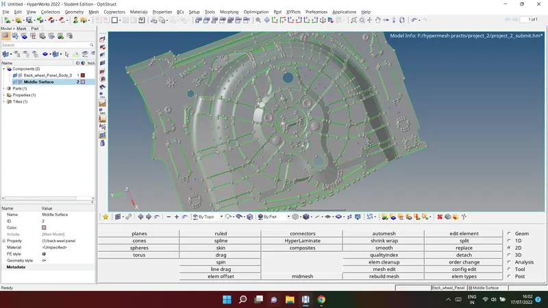
Finite Element Analysis
The finite element method is a numerical technique for obtaining an approximate solution to a wide
variety of engineering problems. FEA (Finite Element Analysis) is done by three phases.
1. Pre-processing
2. Solution
3. post-Processing
This project comes under Pre-processing.
- The goals of Pre-processing are to develop an appropriate finite element mesh, assign suitable material ID and boundary conditions.
- ANSA And Hyper-mesh are the example tools and in this project Hypermesh is used.
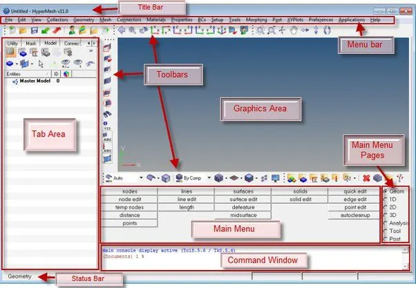
Hypermesh interface
Project_2:
Target Element Length = 4 Units
Quality Criteria
Target Element Length = 5 Units
| S.N | Quality Criteria | Value |
| 1 | Aspect Ratio | 5 |
| 2 | Skewness | 45 |
| 3 | Warping | 15 |
| 4 | Taper | 0.5 |
| 5 | Min. Length | 2 Units |
| 6 | Max. Length | 8 Units |
| 7 | Min angle Quad | 45 |
| 8 | Max angle Quad | 135 |
| 9 | Min angle Tria | 20 |
| 10 | Max angle Tria | 120 |
| 10 | Tria % | 10 |
Procedure:
The meshing is done by following steps
1. Import side_door_panel.hm in to Hypermesh
2. CAD Geometry clean up and topology
3. Mid-surface extraction
4. Defeaturing
5. Shell meshing
6. Creating properties and Thickness assigning.
1. Import project_2.hm in to Hypermesh
Import project-2.hm in to Hypermesh :file>open>model, browse the file and open. in the figure below
shows the model.
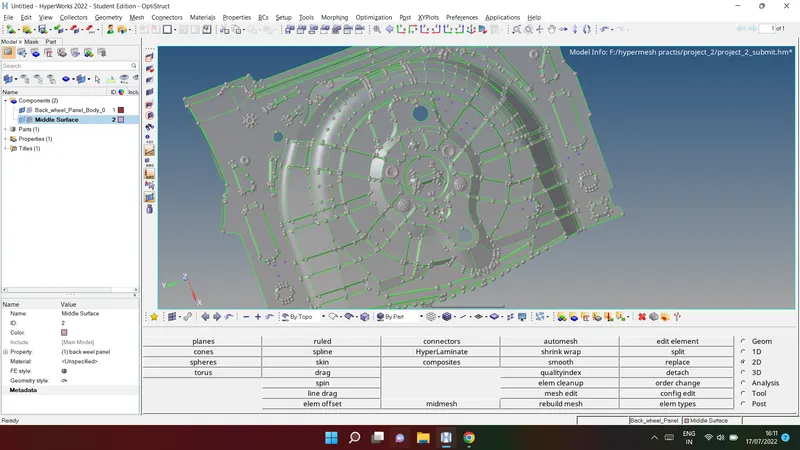
From the imported file we can see so many features such as Ribs, Locators etc. So that this component has different thickness on each feature.
2. CAD Geometry clean up and topology
CAD Geometry clean up and topology step the given model undergoes geometry check.
Where all the defects such as collapsed faces, cracks, free edges, T-edges are clear.
show description on surface.
Tools used in topology
- Equivalence (multiple edges at a time) Search surfaces for pairs of free edges and combine into
shared edges - Toggle (edge pair at a time) Select an edge; equivalences with other free edges found within a user
specified tolerance - Replace (1 edge pair at a time) Select 2 edges to equivalence together. Control which edge to retain
and which to move. - Geom>Surfaces>Ruled or Geom> Quick edit > filler surface or 2d> spline> surfaces only (to create
missing surfaces).
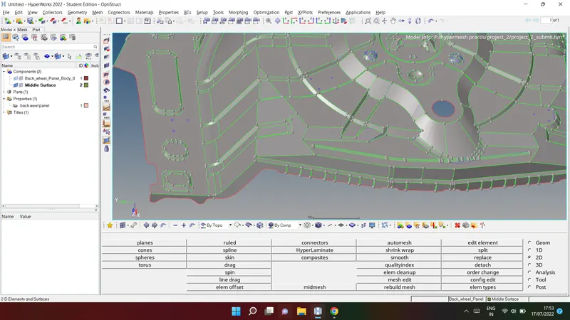
Defeature all small fillets by using
steps
a. Geom>Defeature>surface fillets
b. Use the Surf Fillets subpanel to identify and remove surface fillets (curved surfaces that create a
smooth transition between relatively perpendicular geometric entities). You can identify fillets based
on radius, because fillets are always uniform arcs. You can also select a fillet by picking one of the
edges that it connects. Once found, fillets can be removed using tools that display automatically after
the find process.
c. By clicking on remove all selected fillets will be removed.
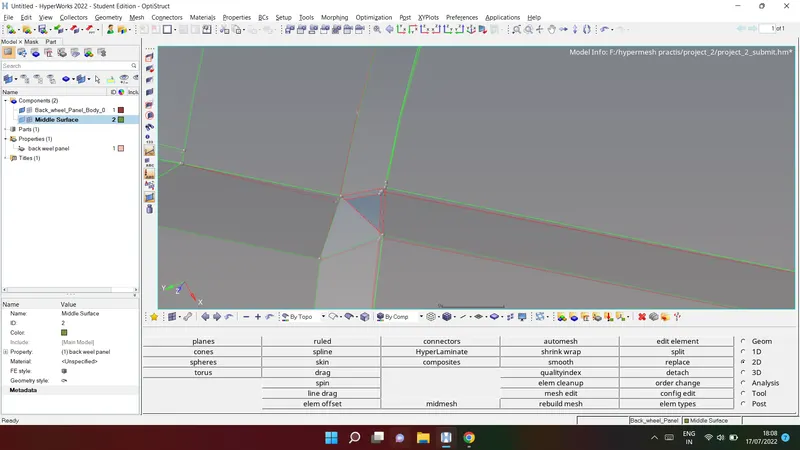
ill missing surfaces using line drag: Use the Drag Along Line subpanel to create surfaces by dragging
lines or a node list along another line, called the "drag line".
Steps
a. Select the lines or node list to drag.
b. Select the lines that the drag will follow. This can also be a series of connected lines.
c. Merge the input lines into smooth lines when possible, and create a surface for each group that
forms a tangentially continuous line.Clear this checkbox to create a surface for each input line, with
shared edges connecting surfaces where relevant.
d. Choose where to organize the resulting surface component.
3. Mid-surface extraction
Mid-surface extraction on the given model is a side door panel and before going to the Mid surface
extraction check for thickness of entities and measure (Geom>distance).
We found different thickness on each feature. To simply extraction of mid surface. models divided
in to two components
Mid surface is done by manually using offset
(Geom> surface edit> offset). offset panel
Steps
a. select offset
b. Offset moves the selected surfaces without retaining their connections to surrounding geometry.
c . select the surface and make a duplicate of same surface
d. input the value which is half of the thickness
e. to check the direction click on vector normal so that we can see the offset direction, also one can
change the direction by reverse normal
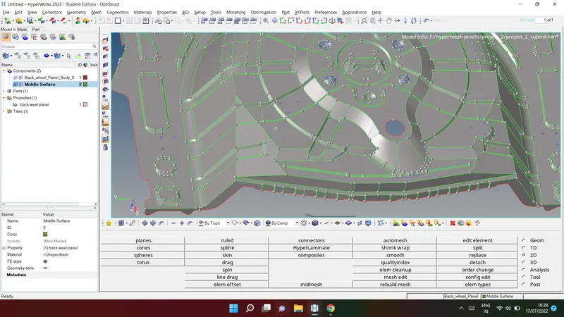
4. Defeaturing
Defeaturing is to update the Criteria length as per given element Quality criteria which
is Target/Average length
Removing all unnecessary edges, fillet radiuses etc. also maintain distance
between two edges or nodes not less than Minimum Length of 2.
tools to Defeaturing
A. Toggle edge
Left-click a free edge (red) to make it shared (green), or a shared edge to make it suppressed (blue).
Right-click a suppressed edge to make it shared, or a shared edge to make it free.
In either case, the edge must meet the criteria for the type of edge you wish to change it to. For
example, toggling a free edge to a shared edge requires the presence of a similar edge within the
distance you specify in the tolerance field.
B. Replace (1 edge pair at a time) Select 2 edges to equivalence together. Control which edge to retain
and which to move.
C.filler surfac
Geom> Quick edit > filler surface (to create missing surfaces)
5. Shell meshing
Shell Meshing is Before meshing Assign given element Quality criteria in to hypermesh by
Preferences>criteria file setting shown
Target Element Length = 5 Units
| S.N | Quality Criteria | Value |
| 1 | Aspect Ratio | 5 |
| 2 | Skewness | 45 |
| 3 | Warping | 15 |
| 4 | Taper | 0.5 |
| 5 | Min. Length | 2 Units |
| 6 | Max. Length | 8 Units |
| 7 | Min angle Quad | 45 |
| 8 | Max angle Quad | 135 |
| 9 | Min angle Tria | 20 |
| 10 | Max angle Tria | 120 |
| 10 | Tria % | 10 |
Start meshing Process by Automesh (2D>Automesh )
steps to mesh
a. Select surfaces for initial mesh and for remesh select elements.
b. select size and bias abd select mesh size which is Target/Average length 5. Use the Size and Bias
subpanel to perform size and bias meshing, a flexible and powerful meshing method. A minimum of
inputs are required for the element criteria settings. The algorithm options set preferences on how to
handle certain situations when encountered in the geometry. When using existing finite elements as
the basis for mesh generation, feature recognition settings allow the mesher to break up the areas
defined by the selected elements into logical groupings with mesh controls set for each group
boundary.
c. Select the type of mesh as mixed (Quad, Tria, mixed, R tria etc) and clock on alin and size in order to
get proper mesh near features.
click on mesh or middle mouse button
Modify mesh flow by changing surfaces to elements and select the elements.
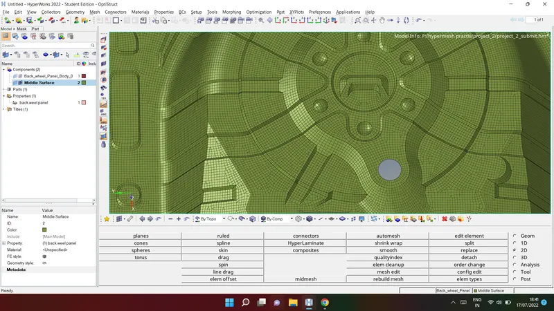
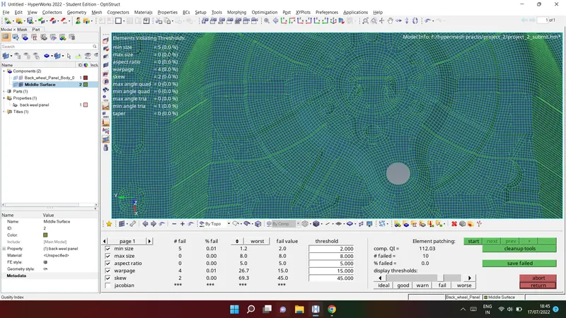
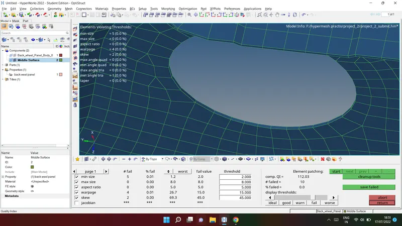
Remove all quality failing elements by smoothing, by changing distance, angle b/w the nodes of failing
elements we can see 0 elements are failed
check quality criterea
6. Creating properties and Thickness assigning.
6. Creating properties and Thickness assigning: Not only property we can create components,
material, Cross sections etc by right click on Tab area and select requirement
Before creating properties we need to create components for elements as per the different thickness.
right click on the Tab area and select component to create components. in the fig.6.2 shows the
components as per the thickness. If we have varying thickness (taper).Then divide that region with
respect to mesh flow and assign thickness value from maximum to minimum with equal intervals.
Create property as per the components thickness. To create right click on the Tab area and select
property to create properties.
a.select property, we can see the properties in the tab area.
b. Click on the property and rename, change the thickness, select material, card image and etc. for
each component we need to create property shown in the
Each property card has following properties
Slover keyword
Id
color
card image
thickness T etc
Assign properties to each component by right click on
comp> assign> select property.
In the graphics area we can see the model after applying properties
note: here I have taken avarage thickness 2
view through 2D detailed element reprentation
Result:
Shell (2-D) mesh is done Successfully for Project -2 model by eliminating geometrical errors and
considering the given element quality criteria also assigning thickness using Hypermesh