Week 12:Project 2-Meshing of Rear Wheel Holder challenge
Aim: To Generate manual mid surface and 2D mesh for given component.
Objective:
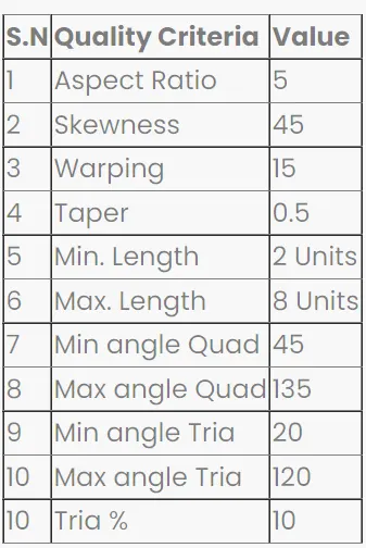
Generate mesh within required quality criteria displayed below with 5units element size ,
Procedure:
Import the model into Hypermesh using Import Geometry tab.
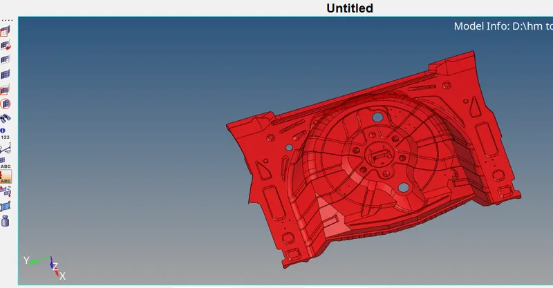
After Importing, switch to topo mode and check whether the components given are solids or surfaces. Thicken lines indicate solids. If they are solids, delete them and convert them to surfaces for midsurface extraction.
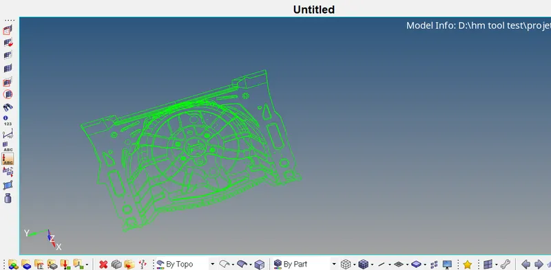
After observing the thickness of each and every component, it is found that the thickness is for the components is same. (0.75mm). So, we extract the midsurface using the auto midsurface option using Skin Offset as extraction option.
1. Dublicate the parent geometry which will help us to avoide loosing the base geometry in the process of mid surface generation.
2. Now proceed with manual mid surfacing procedure,
For midsurfacing follow the given below procedure;
After observing since the thickness of component is same. So, we prefer to extract the midsurface using the auto midsurface option using autoextract as extraction options.
Geometry> Quick Edit
Once the mid surface is generated we can move further with geometry cleanup procedure where we can simplify the geometry for better mesh flow and minimal errors.
For geometry cleanup we use quick edit panal , here we toggle the unwanted lines and replate the unwanted points, we also split the surface for better mesh flow and ease of working.
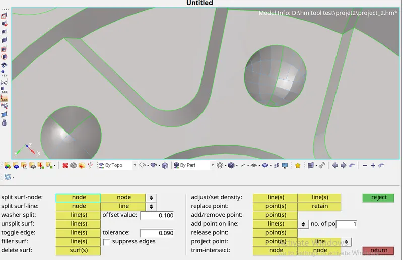
Now the geometry is ready to mesh,for meshing;
Before meshing set the required quality criteria as shown below;
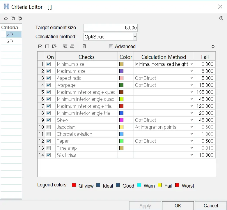
for meshing follow the below procedure;
2D>Automesh>Surface>Element size (5)>Element type(mixed)>Mesh
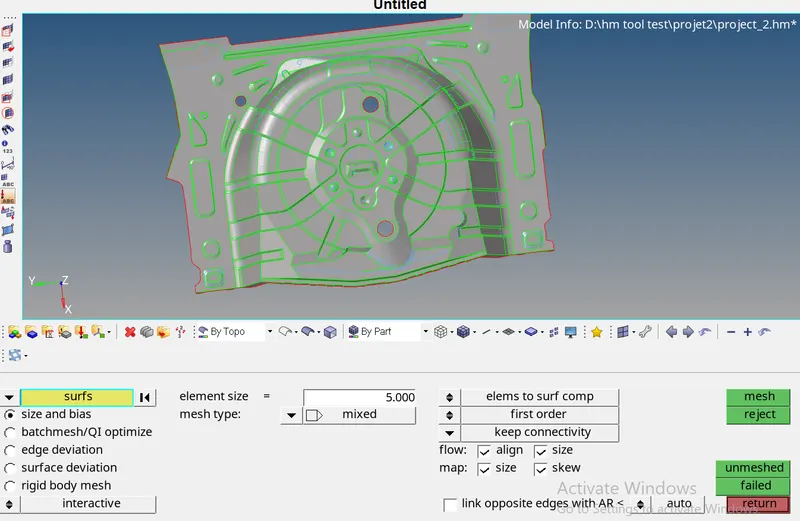
Always keep the flow Align and size option ticked as it will give a much better mesh flow on the component. The basic rules while meshing are to be followed here, such as that there should be no tria element on a feature line and even to avoid the rotational Quad elements in the mesh.Keep the tria count as low as possible because Tria elements are much more stiffer than Quad Elements.
For better mesh flow and control over the nodal number, the geometry be can divided into much smaller segments that can be meshed individually.
After meshing the entire mid surface, the mid-surface should look something like the following:
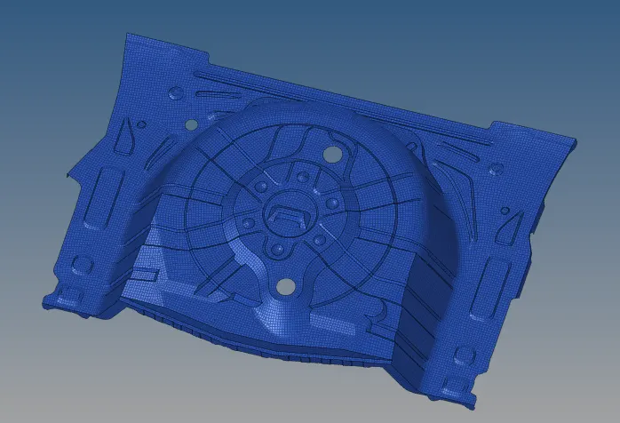
Chech the quality of mesh and rebuild the mesh if required depending on the quality criteria, operations from quality index panel (element optimize, node optimise, swap edge, drag tri, smooth) are need to be used to improvise the mesh quality and reduce tri elements.
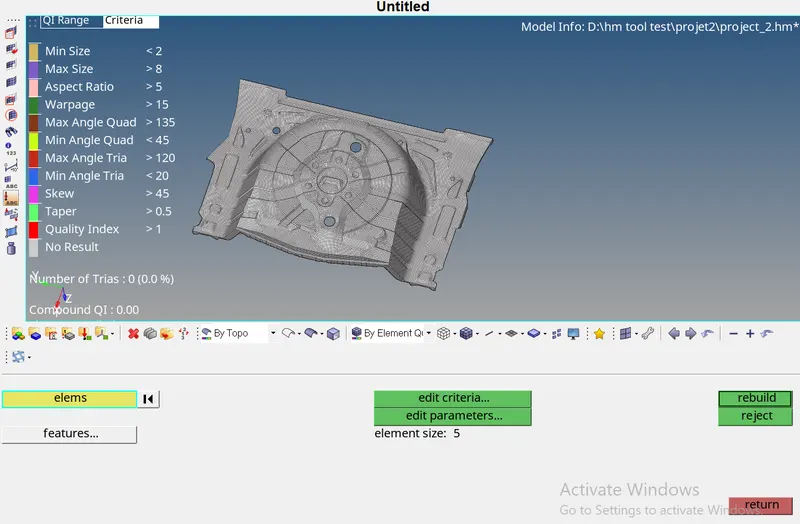
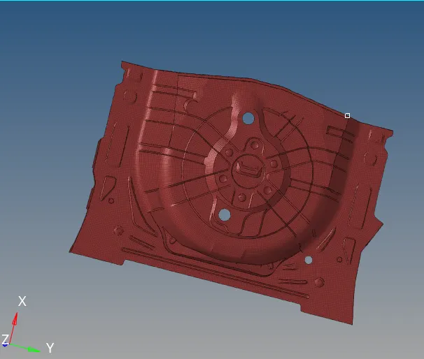
Final mesh with optimum mesh quality;
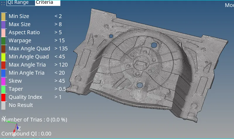
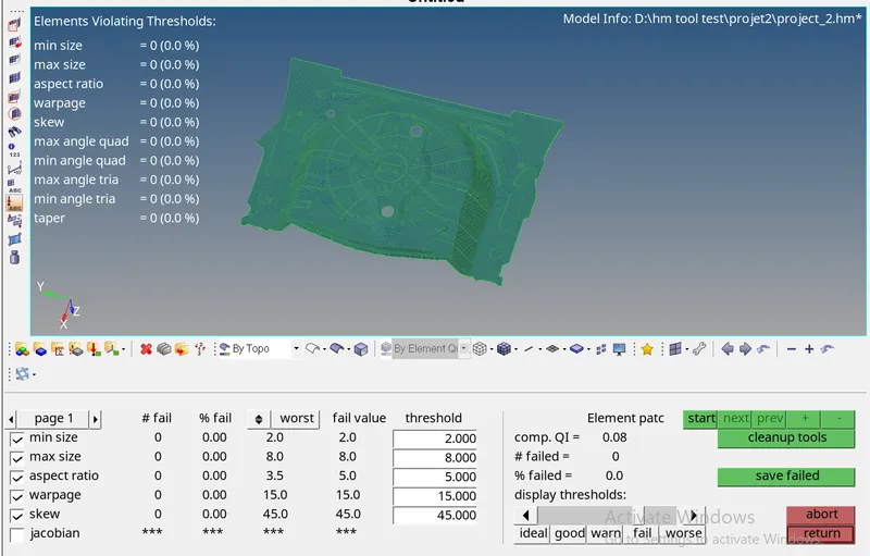
Once the meshing is done the next step is to apply thickness to the mesh geometry
for applying thickness , Create Property card> Add thickness (t=0.75)>assign property card to every component.
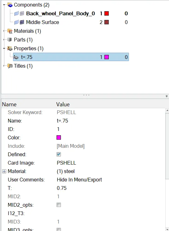
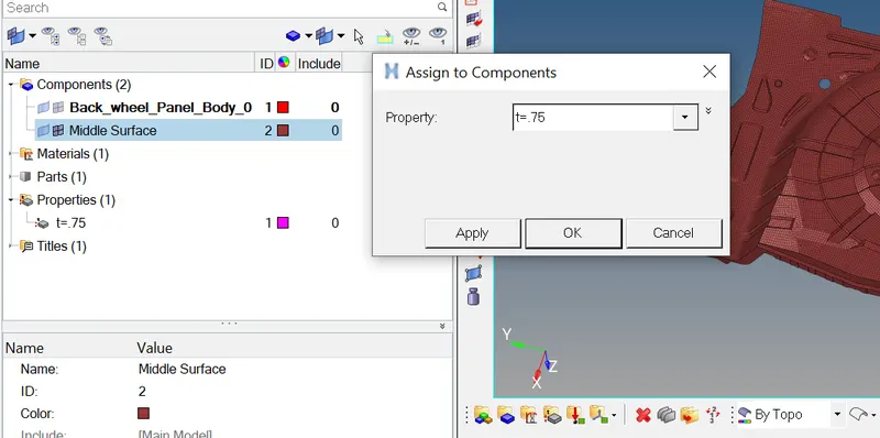
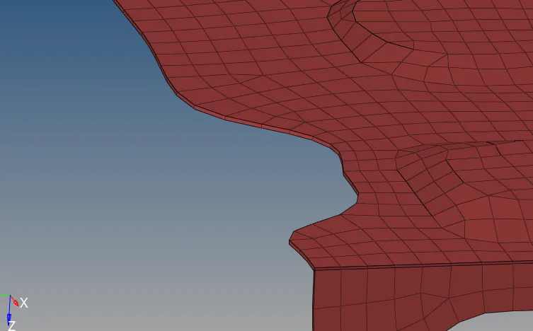
Thickness Representation on mesh:
Conclusion:
Here we've successfully generated a midsurface and a mesh within the required quality criteria for Rear Wheel Holder.