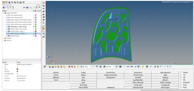
Week 12:Project 2-Meshing of Rear Wheel Holder challenge
Step 1. the given component has been imported into the hypermesh with optistruct profile.
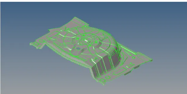
After that any solid from the surface is deleted from the components.

The given component has few igeometric errors which are to be fixed manually so that to generate a perfect mid surface of the component.
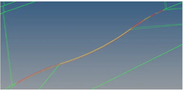
The given problem can be fixed by replacing the lines and using fillers surface which is persent in quick edit submanu of geometry toolbar.

After geometry cleanup next, to define the criteria the file which is required by our model meshing.
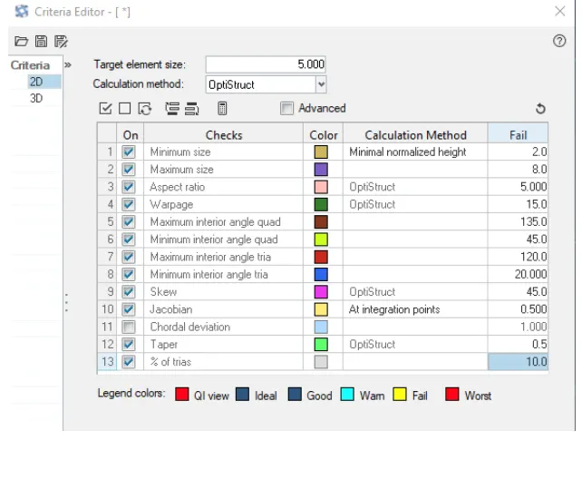
Step 2.
After meshing next step is genertae the midsurface for meshing.
Midsurface modeling is a technique for creating a simplified shell reperesentation of a solid model.
Midsurafce modeling can reduce the computational expense of analyzing a complete solid model when bee shell model with a define thickness and fewer details is suitable for the required analysis.
Midsurface gemeration by the geometry toolbar provided in the hypermesh.

We have selected automidsurface option with offset+planes+sweep midsurafec option present with the model.
After midsurface we get the following components.
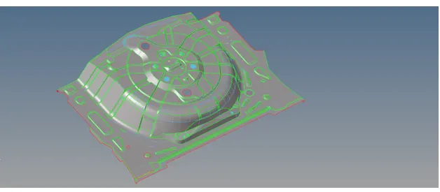
As the model generated has some geometry problem, we need to clenup the midsurface before meshing the components.
Step 3.
Next step is meshing the components.
Meshing is an intergal part of the engineering simulation process where complex geometries are divided into simple element that can be used as discreate local approximations of the large domain.
The mesh influence the accuracy, convergence and speed of the simulation.
We have generated 2D mesh, for meshing.

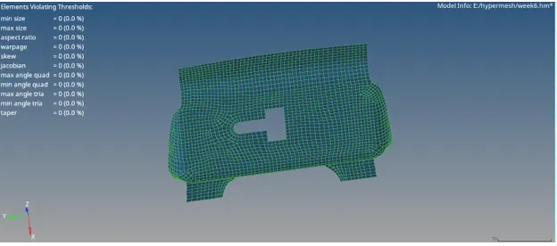
After meshing we get the following components.
After meshig the component consist of bad element which does't meet the criteria.
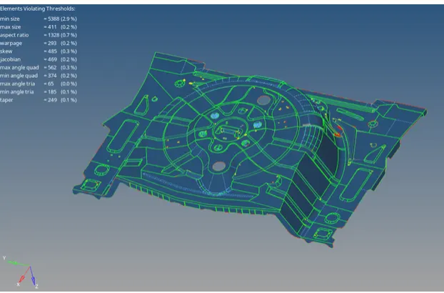
These element need to be cleaned to get the requirment mesh criteria.
The failed element can be fixed using the element fixing tools in the quality criteria manu.
While using the quality criteria menu the failed elements are highlighted in yellow and red colors.
Yellow errors indicate that the errors can be fixed easily, whereas the red color indicates critical errors
Results
After cleaning the elements of few bad element its basic of skewness at sharp corners which can't ba cleaned.
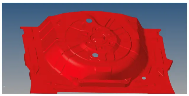
After that thickness is assigned to the co ponents by creating the property card for the parts.
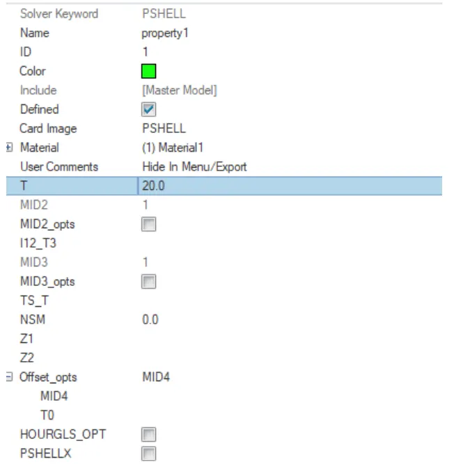
After creating the property this card is assigned to the component which provide the desired thickness.
=>. Geometric cleanup
Inthis Report, I will conduct the Geometric cleanup for 3D models
. Practice
. Clip Repair
. Mouunting Bracket
The purpose of geometry cleanup is:
. Refine the geometry
. Create reasonable mesh
. Assign proper thickness
The proc edure is as follows
. step 1. Improt CAD model.
. step 2. clean the geometric : delete bad edges, delete temp nodes, fill surfaces, toggle edges with tolerances
. step 3. When the topology is good , conduct the midsurface extraction
. Step 4. Look for holes with diameter samller than 5mm and delete them.
. step 5. create mesh for the whole model with averga element size 5mm and refine the mesh accotrding to mesh quality criteria.
. step 6. Assign a proper thickness.
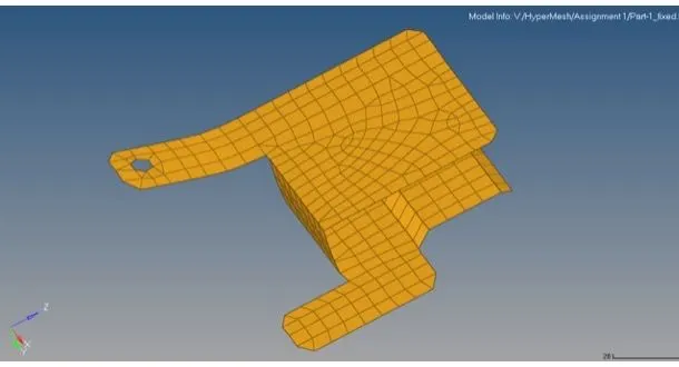
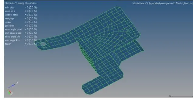
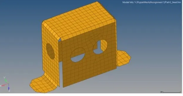
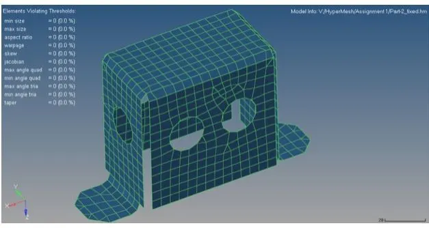
Result of meshed models
1.. part 1
mesh :
. mesh metrics
2. part 2:
. mesh
. Mesh metrics:
3. part 3:
. Mesh:
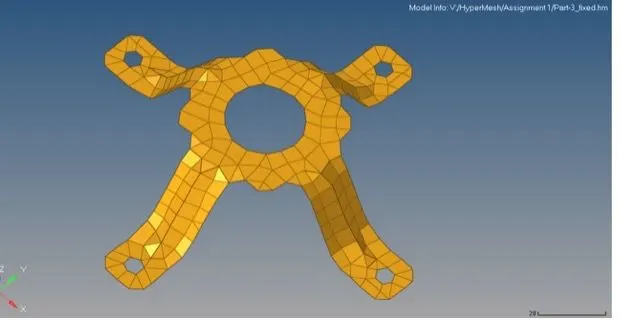
. Mesh metrics:
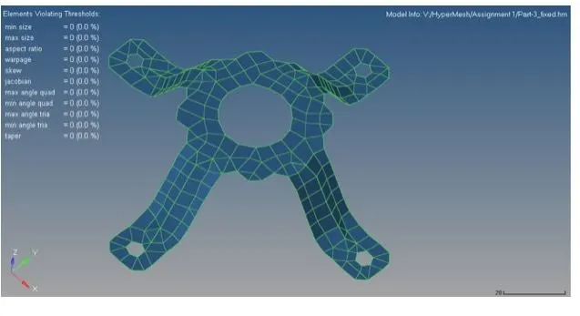
Conclusions:
1. The geometrics were slightly modifined to facitilate meshing.
2. The geometrics have thickness smaller then 2 mm ---> we can simplify them as shell property using the function midsurface.
3. To avoid bad elements, holes with diameters smaller than 5mm are filled.
4. The final mesh size stay within ranges of mesh quality criteria.
=> . Mesh quality parameters in the finite element analysis
The shape of elements in FE analysis must be distorted from their ideal shape when meshing the irregular or complex geometric shapes.
Every element is designed to work properly within is crtain rangeof shape distortion . exactly how much distortion and what types of distortion is allowed before an element degerates depends on factor
---------------------------------------------------------------------------------------------------------------
OBJECTIVE
mesh the given hood model in hypermesh using the given quality criteria.
target element lenght 5mm
Procedure
.Import the model hood file into the hypermesh..
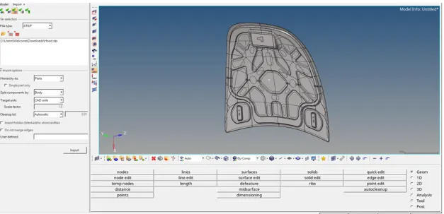
. We have to mesh the componet separately.
. We have to delete the solid in the model delete-solid select the solid-click delete.
. Hide the surface and element of the component by geom-midsurface-extraction-offset+planes sweeep-extraction to create the midsurface of the model.
. The auto cleanup the midsurface geom - autoclean up - selet the surface.
. Then mesh the component 2D - automesh-select the surface-mesh, give the element size 5 and select the types quad.
. Then give the quality criteria in tool- check elems.
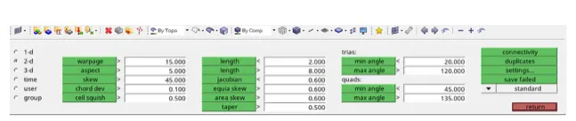
. Tool used to meet the quality criteria by 2D-quality index-clean up tool
1. Plece node is used to move the nodes
2. Node and element optimize is used to optimize the element automatically.
3. Smooth is used to smooth the curvature.
4. Drag tria element is used to drag the tria element out.
5. Split quad is used to split the quard element into two quad.
6. Combine tria is used to combine tria element into quad.
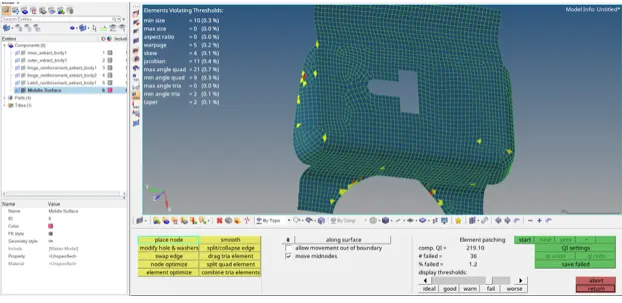
Tools used to meet the quality criteria by tools
1. meak is used to mask the failure element
2. Edit element is ued to create, the split and combine the element
Then give colors to the component to differetiate.
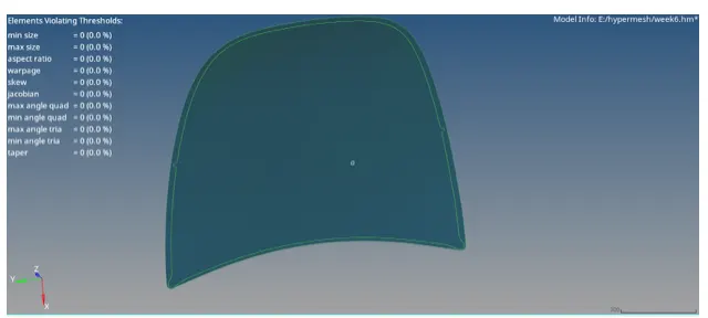
OUTER BODY
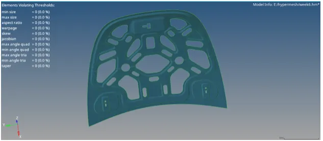
INNER BODY
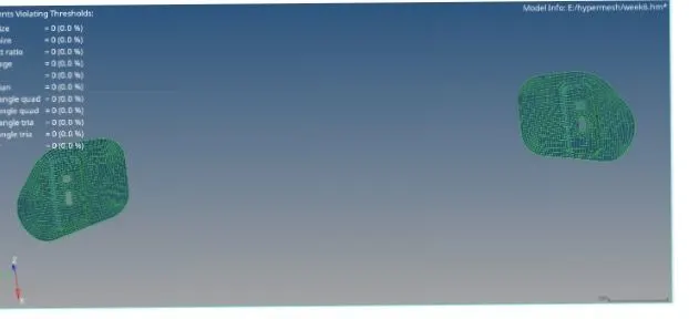
HINGE SURFACE
LATCH SURAFCE
RESULT AND CONCLUSION
. Learnt how to do mesh the component in given quality criteria.