Week 12:Project 2-Meshing of Rear Wheel Holder challenge
AIM : To extract the midsurface for the given component and to mesh it with given quality criteria and mesh parameter.
PROCEDURE:
Step1: To Import the given model to the GUI or sover deck.
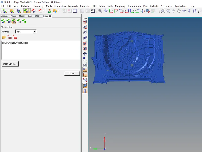
- Import file>selecting file type>Import.
Step2: Now to generate the Mid surface for the component.
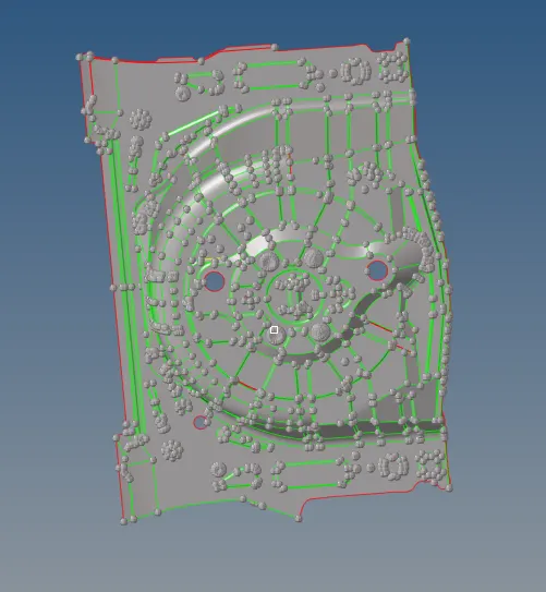
- Geom> Midsurface >selecting the component>Extract.
- The Midsurface is extracted as shown in the above image.
Step3: Performing the Geometry Cleanup.
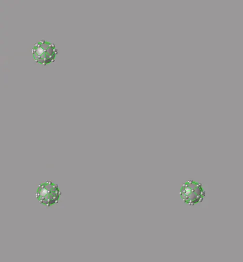
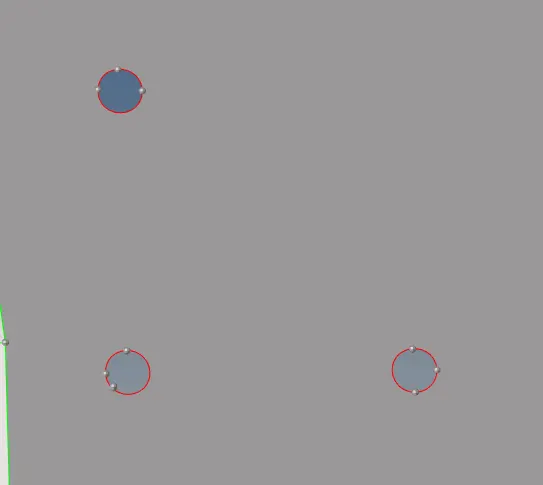
- Removing the kinks in the surface ans imperfections
- By delecting the bumps and creating the surface using ruled options.
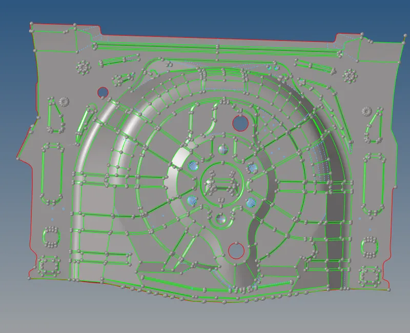
- Similarly removing the unwanted construction lines.
- Also defeaturing some the surface to avoid the failure of the elements.
Step4: To assign the given element quality criteria.
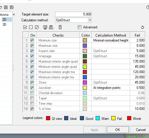
- Perferences>quality criteria> Assigning the given quality criteria
Step5: To mesh the given component.
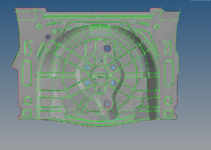
- 2D Mesh>Auto mesh > elemnt size> mesh
- In order to have good mesh flow selecting surface by surface.
Step6: Fixing all the element quality failure.
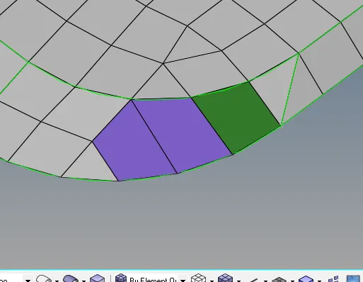
- The above element have failed for the Maximum length and warpage.
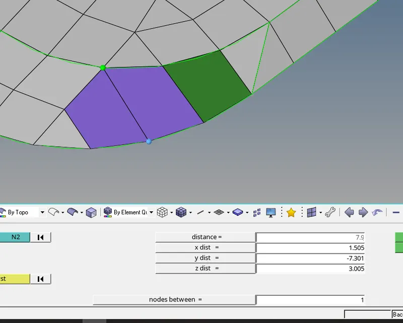
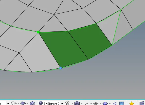
- By using Geom>distance option or F4
- Selecting the maximum distance node and assigning the appropriate distance>enter key > the blue node will be moved accordingly.
- Now the maximum element failue is removed.
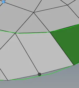
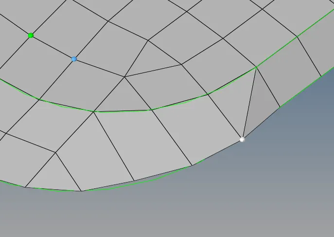
- Using Check element or F10 option to know the elemet details
- Using translate option or Shift F4 to remove the quality
- Selecting the node>distance>giving the direction N1 and N2 accordingly,using translate+/- to remove the element failure.
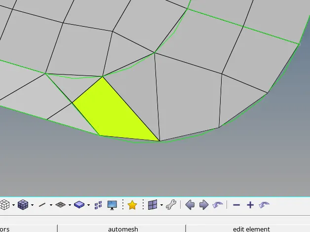
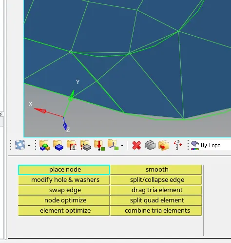
- The above element is failing for minimum Quad angle.
- Using 2D> Quality index>place node option to move the Node
- The quality is removed as shown in the above picture.
- Now the folowing the same procedure or using rebuild m3esh to improve the mesh flow and remove the element failure.
Step7: Assiging the material and property to the component.
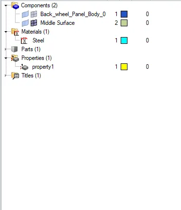
- Right clicking on the model Tab>create>property> assigning the values and material
- Similarly steps for the materials .
- Now right clicking on the component >Assign option >selecting the property .
Step8: To move the elements or surface to the components.

- Tools> Organise> selecting the elements or surfaces> dest- selecting the component> Move.
- The elemts or surface is moved.
Step8: To find the free edges in the components.
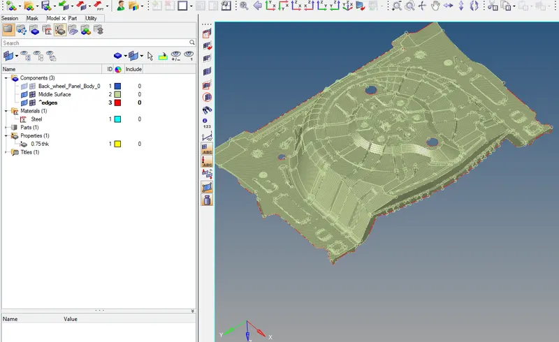
- Shift f3 or Tools > Edges> elements ,displayed> The free edges are highlighted in red colour
- If the free edges are present in the between the elemets it is highlighted in red in colour
- Using replace or f3 to attach the nodes
- Using preview eqvi and equivalence option to attach the nodes.
Pictures of the model:
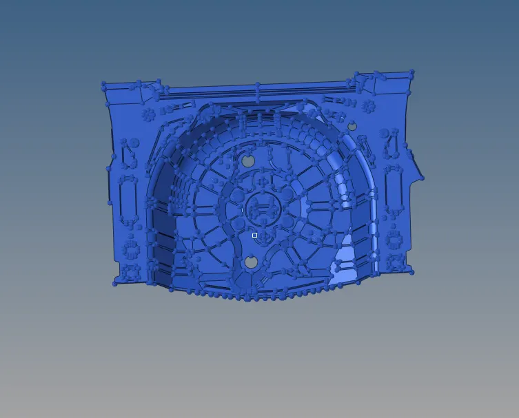
i) Parent Geometry: ii) Mid surface:
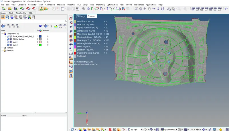
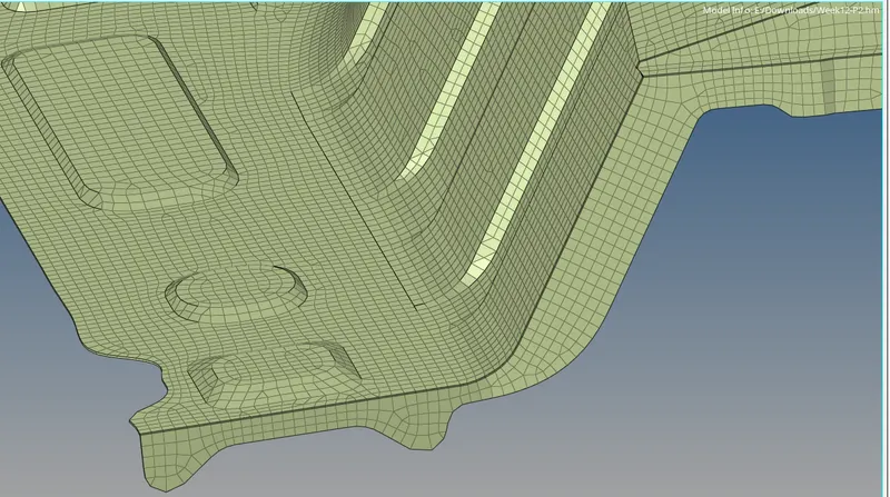
iii) Meshed component and satisfying the element quality criteria: iv) Thickness enabled:
RESULT: Successfully extracted the midsurface and meshed the component with the given quality criteria
and mesh parameter