Week 12:Project 2-Meshing of Rear Wheel Holder challenge
AIM:
To extract the mid surface of given component and mesh the component under given quality criteria and assign thickness.
OBJECTIVE:
- To extract the mid surface and mesh it with proper mesh flow.
- To ensure the mesh should pass the given Quality Criteria.
- To assign thickness to all the components of the model
GIVEN:
Target Element Length = 5 Units
| S.N | Quality Criteria | Value |
| 1 | Aspect Ratio | 5 |
| 2 | Skewness | 45 |
| 3 | Warping | 15 |
| 4 | Taper | 0.5 |
| 5 | Min. Length | 2 Units |
| 6 | Max. Length | 8 Units |
| 7 | Min angle Quad | 45 |
| 8 | Max angle Quad | 135 |
| 9 | Min angle Tria | 20 |
| 10 | Max angle Tria | 120 |
| 10 | Tria % | 10 |
Remove the buttons which are shown below because it will be difficult to capture that area as well mesh flow will not be proper. Except this feature, all the other features should be captured with proper element quality
SOFTWARE USED:
Hyper Works 2021
GIVEN MODEL:
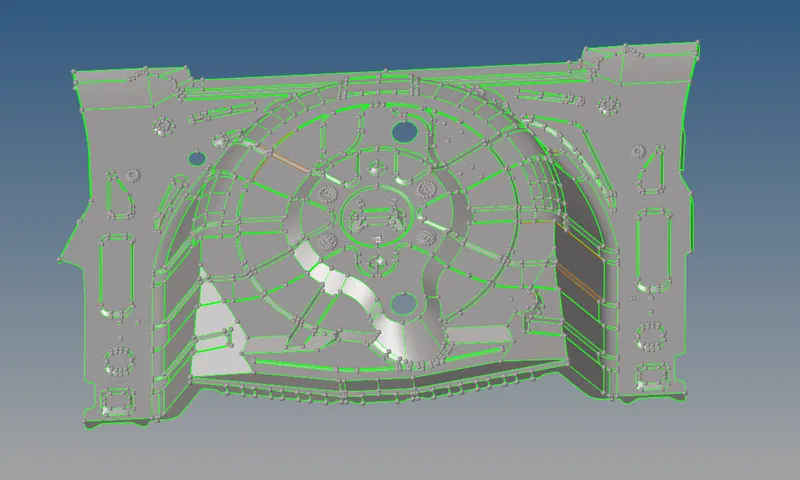
GIVEN MODEL
BRIEF PROCEDURE:
Step 1 : Import given model and Geometry clean up for given component.
Step 2 : Extraction mid surface using different options.
Step 3 : 2D mesh on extracted mid surface under given criteria.
Step 4 : Assign various thickness for each parts.
STEP -1 : IMPORT GIVEN MODEL AND GEOMETRY CLEAN UP
- Import the model by using IMPORT option.
- Visualize the model for find deformities in its surface or free edges,which can be visualized in wireframe mode and By Topo mode and repaired.
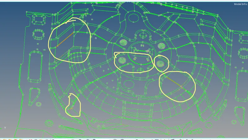
MODEL WITH FREE EDGES
- Make sure about the surface errors before start to take mid surface.if you see unwanted free edges in the surface repair using correct step.
- BY TOPO mode you easily find the free edges
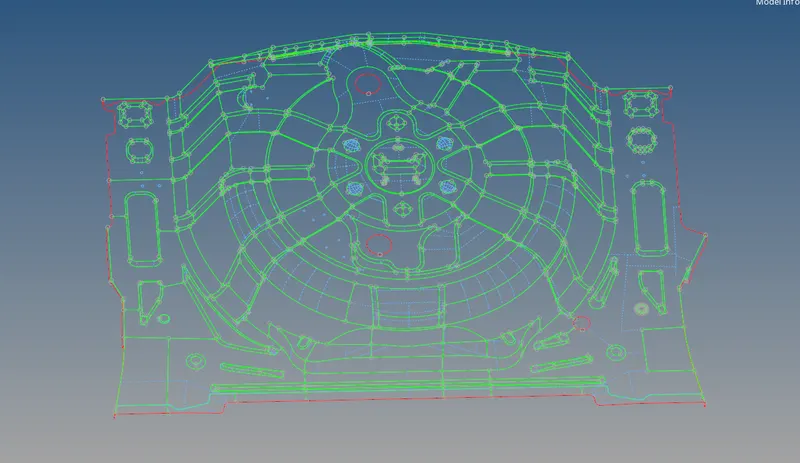
CLEANED MODEL IN BY TOPO MODE (WIRE FRAME)
Step -2 : EXTRACTION OF MID SURFACE
- First extract mid-surface for given component by following steps
Geom→mid surface
- And also carried out several geometry edit for getting good mesh flow.we toggled unwanted topology lines which makes element failure.
- But always careful we never remove feature edges.
- Defeature the buttens which are given and fill the gap by using following steps
Geom→surface
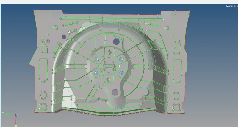
FINE MID SURFACE
- Now the mid surface is extracted properly as shown in figure.
Step -3 : 2D MESH ON EXTRACTED MID SURFACE UNDER GIVEN CRITERIA
- Before start mesh we need to set meshing Quality criteria by using preference menu
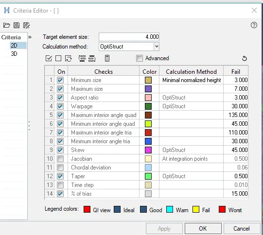
CRITERIA FILE SETTING
- Now we can start the 2D shell mesh for the component by using following steps
2D→automesh
- We mesh the mid surface by element size as 4 and mixed elements.
- First we should start from complex surface to get good mesh flow.
- While meshing we should maintain the tria percentage as low as possible.
- We can maintain trias in the direction of the mesh flow.
- We should avoid opposite trias.
- Use REBUILD option for getting better mesh.
- Split the surface before start meshing it gives good mesh and fine flow.
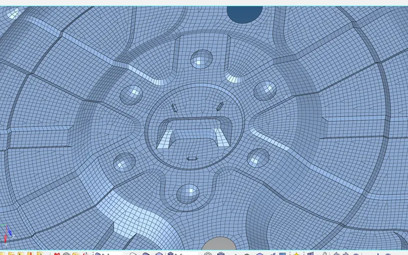
MESH FLOW IN CENTER
- Try to make the mesh flow towards big end to small end, it gives good flow.
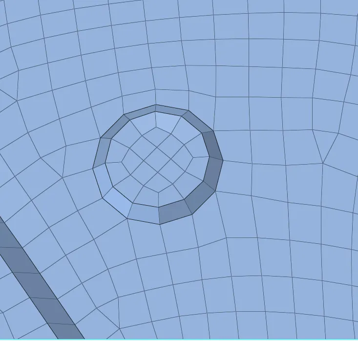
MESH OF BUTTON
- These kind of QUADS are acceptable on these buttons.
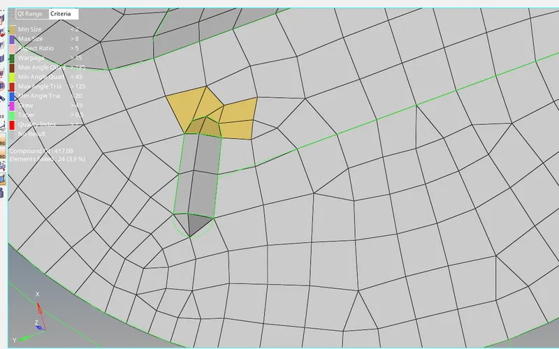
TWO TRIAS
- For capture the feature and pass the quality criteria the two continues trias are acceptable.
- In this model some surfaces are symentric so we mirror the mesh by using following steps
Tool→reflect
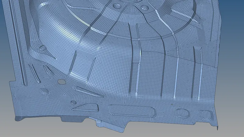
SOME SYMENTRIC PARTS
- It reduce the time and effort.
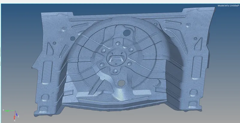
OVER ALL MESH AND FLOW
- While meshing the elements are fail because of criteria,that failure is cleared by using QUALITY INDEX.
2D→quality index
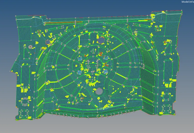
VIEW THE FAILED ELEMENTS USING QUALITY INDEX
- But always careful with feature areas because it disturb everything.
- Try to clear all errors by using remesh,rebuild mesh.
STEP - 4 : ASSIGN VARIOUS THICKNESS FOR EACH PARTS
- First we need to create PROPERTY and MATERIAL before assign thickness.
- Right click on tab area and select create then Property.now new property is created.
- After creating property rename it and give material, thickness, card imeage,etc...
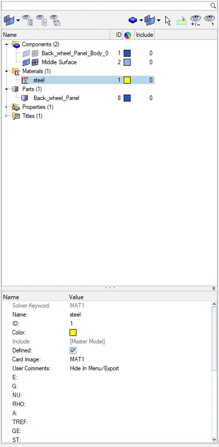
PROPERTY
- Assign properties to each parts by following steps
Right click on component > assign > select property
- After assign see the difference to use 2D Detailed Element Representation .
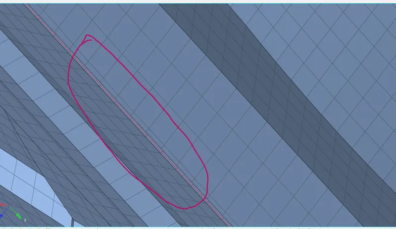
2D Detailed Element Representation
- At the end one important step should check that is find free edges,
Tool→edges
- If find any edge that means there is no connectivity so make the connectivity by using following steps (F3)
2D→replace
FINAL MODEL:
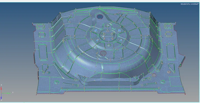
FINAL MODEL
RESULT:
2D(Shell) mesh is done for given model under given criteria and thickness assigned succesfully using Hypermesh. Learned the mesh and feature capture for complex component.