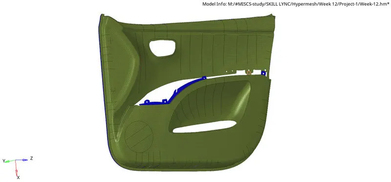
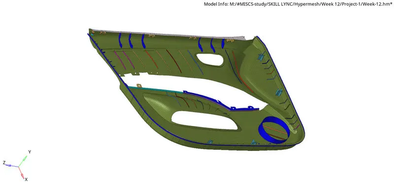
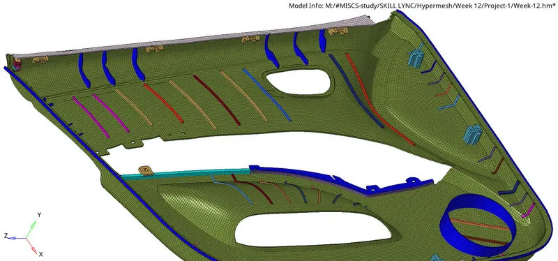
Week 12:Project-1-Meshing of Door Inner Panel Challenge
Objective:
To create midsurfaces and mesh the given component by satisfying the required quality criteria.
Procedure:
Import model:
- To import the cad model, goto New model > Import geometry and select the file to import.
- As only shell meshing is to be performed, Solids are not necessary. Hence, Goto Delete > Solids and delete all the solids present in the model.
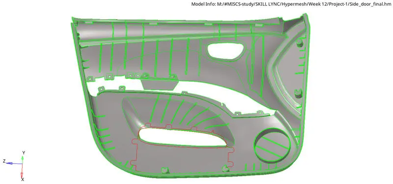
Midsurface generation:
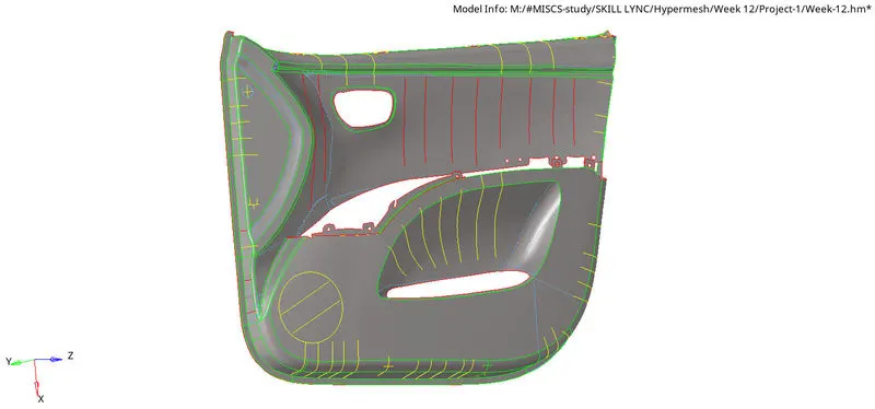
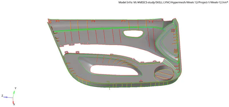
- To create the midsurfaces for the components, goto Geometry > Surface edit, choose Offset and select the surfaces to which the midsurface has to be extracted from and then enter the offset value.
- Then, Click on Offset.
- Use the Surface edit > extend and the surface trim options to extend and join the perpendicular surfaces like ribs, doghouses etc.
Geometry cleanup:
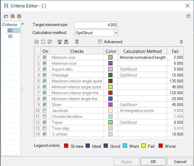
- To start with, goto Geometry > autocleanup and enter the target element size as 4 in the edit criteria & edit parameters menu.
- Select the surface to be cleaned up and click on autocleanup.
- The autocleanup function generates washers automatically.
- Manual cleanup can be done by using the quick edit > toggle edge, quick edit > split surf, quick edit > washer split, quick edit > unsplit surf, quick edit > project point & quick edit > replace point.
- Remove all the unnecessary points by using the quick edit > add/remove point.
Individual component creation:
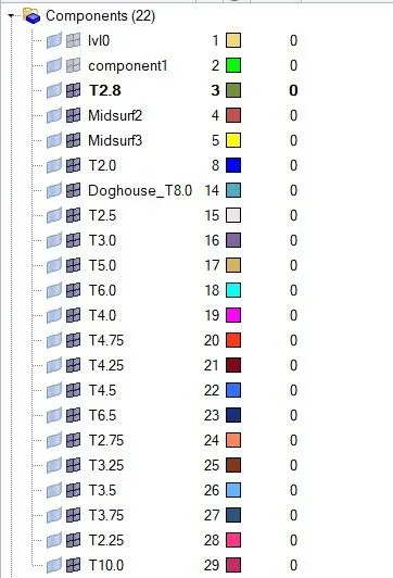
- To assign the different thickness surfaces to different components, Right click on the Model browser and click on Create > Component.
- Then in the panel area goto Tool > Organize, select the surface and the respective component to which it has to be assigned and click on Move.
Property creation:
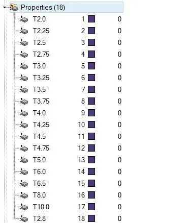
- To create a property, right click on the model browser and click on Create > Property. Choose the card image as PSHELL and enter the required thickness.
- To assign a particular property to a component, goto that component and click on property and select the desired property card.
Quality Criteria File settings:
To define the required Quality criteria, goto Preferences > Criteria File settings > Criteria Editor and enter all the required criteria.
Mesh generation:
- Next in order to mesh the surfaces, goto 2D > Automesh and enter the mesh element size = 4.
- Choose the surface to be meshed and click on the mesh button.
- To check the element quality, goto Tools > Check elements or press F10 or goto 2D > elem cleanup.
- The failed elements can be corrected by using the elem cleanup or the elem quality index > cleanup tools or using any of the manual operations like replace, edit element, split, translate, etc.
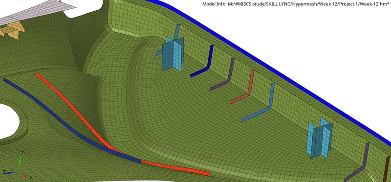
- To project mesh from a perpendicular surface, use 2D > Mesh edit > imprint option. Play with the remain and remesh tabs to get the appropriate result.
Final Checks:
- To check if there are any duplicate elements present, press F10 > duplicates. If duplicates are present, then click on Save failed and goto Delete > elements > retrieve and delete the excess elements.
- Goto Tools > edges, select the surfaces and click on find edges to check if any of the elements are disconnected from the neighbouring elements. To rectify this, click on equivalance or goto > 2D replace and join the nodes manually.
- To check the normals of the elements, goto Tools > normals > elements > displayed elements and click on display. To invert the normals, click on reverse. If any of the elements are not aligned to the neighbouring element's normals, click on adjust or then select those elements and click on reverse.
- To check if the surfaces and the elements overlap each other correctly, goto Mesh > Check > Elements > comparison and choose the target & sources. Enter the tolerance value and click on Run.
NOTE:
- Enable 2D detailed Element representation to view all the elements' thickness.
Result:
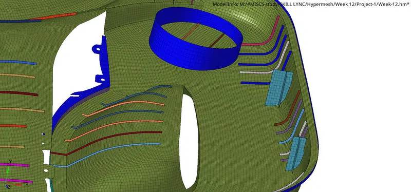
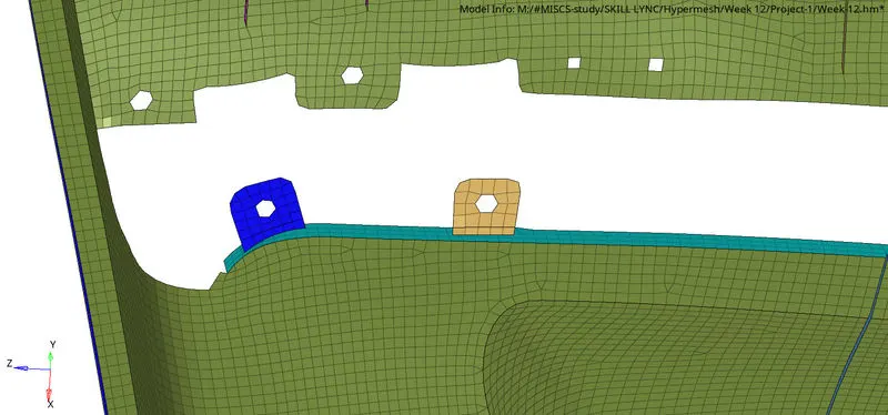
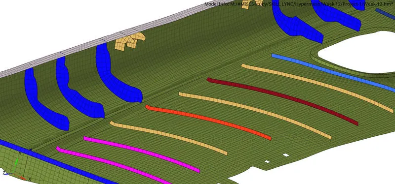
Thus, the given side door plastic model is meshed with element size = 4 units by satisfying the required quality criteria and the thickness was assigned to all the components.