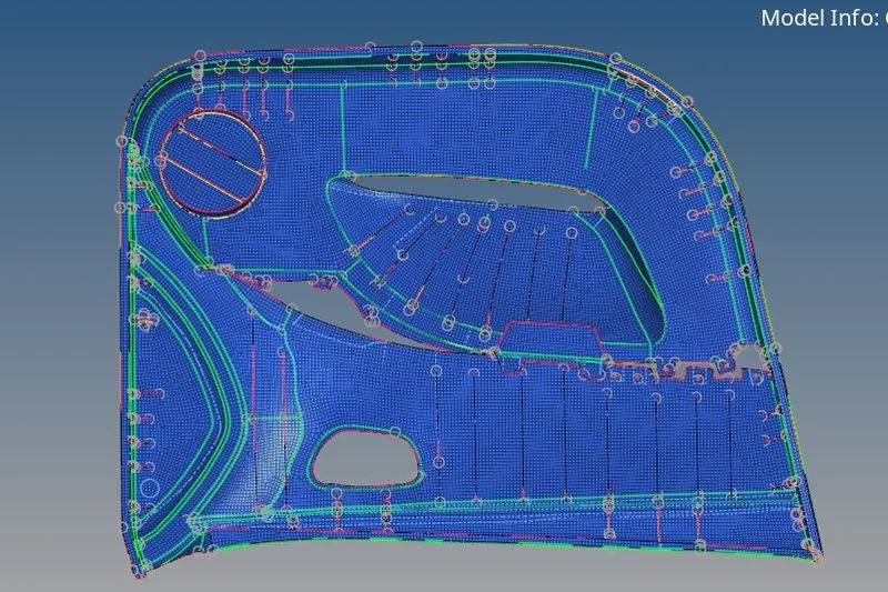
Week 12:Project-1-Meshing of Door Inner Panel Challenge
AIM :
To extract mid-surface, geometry clean up and create the shell (two dimensional )mesh for the given side door inner panel according to the given quality criteria by using HYPERMESH.
THEORY:
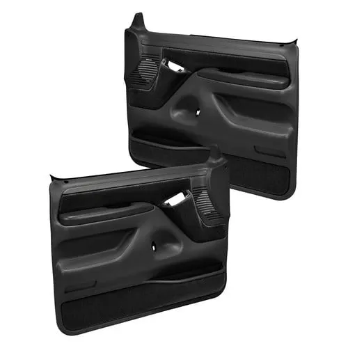
Door inner panel
Door panels serve as an interface between the interior of the car and the inner workings of the door, and between vehicle occupants and the door. They are expected to meet a variety of design specifications regarding safety, aesthetics, and functionality. In addition, they are expected to continue the material theme of the dashboard and pillars while concealing intricate electrical and mechanical components for operating locks, windows, and other features. The door panel has evolved from a simple two-part system of the latch and simple winding mechanism to a more sophisticated enclosure. Doors currently have an inner full-width panel consisting of electronic windows, a central locking system, and speakers. These panels typically consist of a foamed core covered with either textiles or plastics.
PROCEDURE:
Meshing:
First, import the side door inner panel model into HyperWorks.
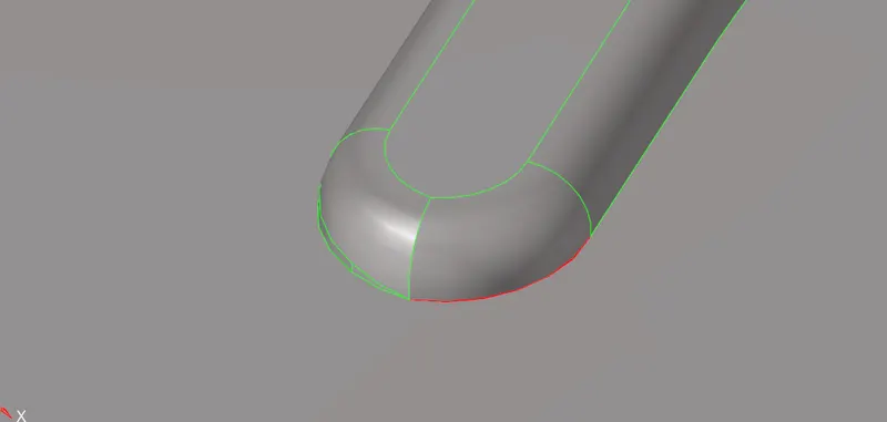
Since there are many ribs with surface fillets, it is difficult to create their mid-surfaces. So, these fillets are removed or defeated by going to Geometry > defeature >surf fillets. Then specify minimum radius, maximum radius, select surfaces and click find. The fillets are shown as highlighted, then click remove to remove the fillets.
Before
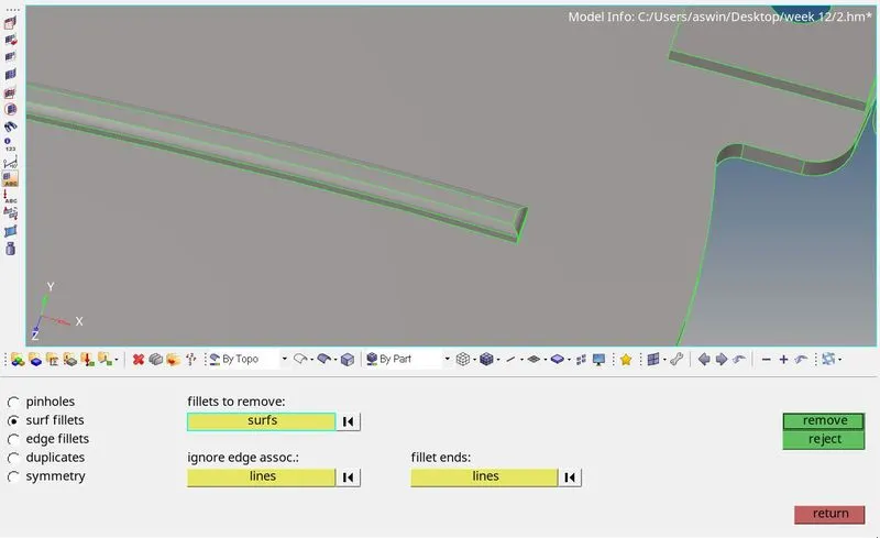
After
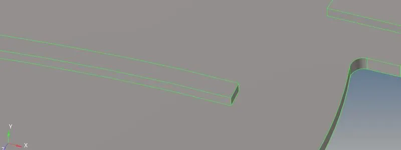
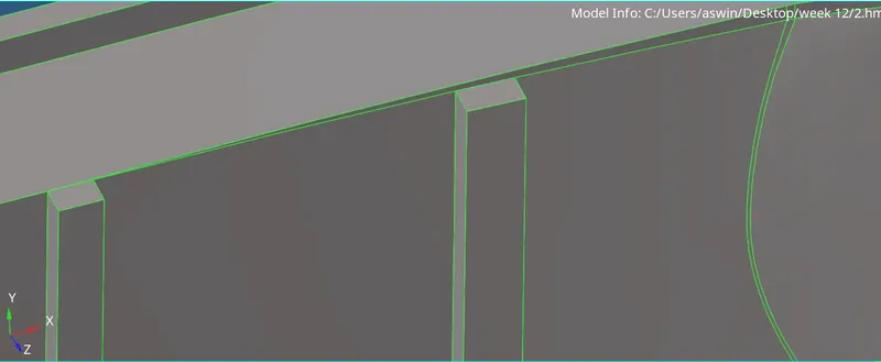
Fix areas like this
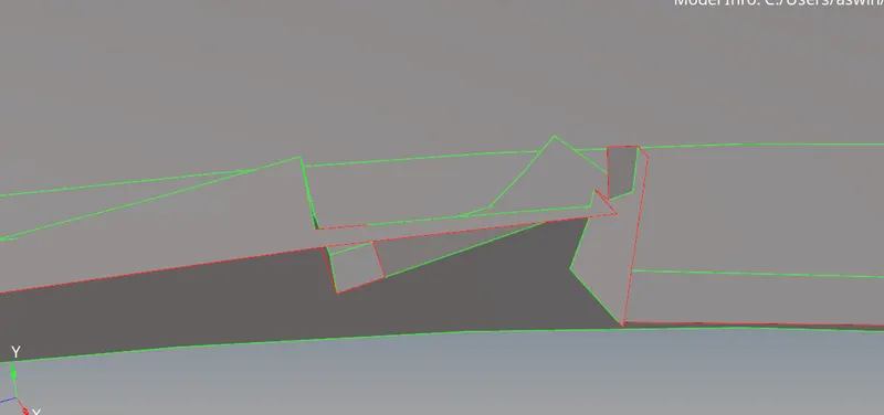
Surface shown below should me made in to one surface as it lead to element failure while meshing for we cann use replace line option.
Before
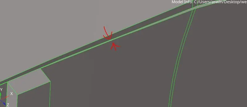
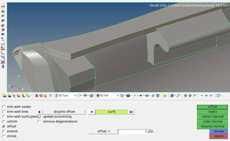
Now, after checking the thickness at various points of the components by Geometry > distance > two points, it is found that the component has varying thickness. So, manual mid-surfacing is done by going to Geometry > surface edit > offset. Then, select the surface and duplicate it, specify offset thickness and click offset and the mid surface is created.
Clean up the geometry of the components for obtaining better mesh.
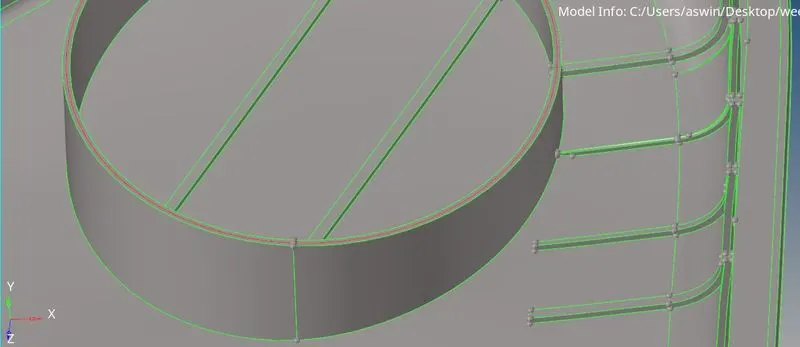
To create the mid surface of the ribs, go to Geometry > midsurface > final edit tools > surface pair, select the surfaces and click extract. There is also a cylindrical surface which can be done in the same procedure.
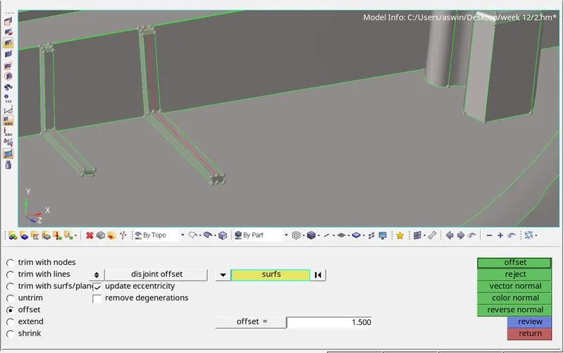
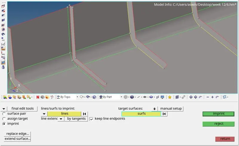
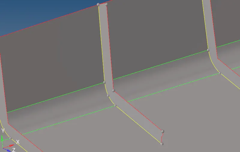
To join the ribs with the base surface, go to Geometry > midsurface > final edit tools > imprint. The imprint of the ribs are obtained on the base surface which can be replaced with the ribs free edge by Geometry > edge edit > replace.
After extracting the mid-surface, the mesh can be created by 2D > automesh > size and bias. Then, assign element size, mesh type , select surface and click mesh.
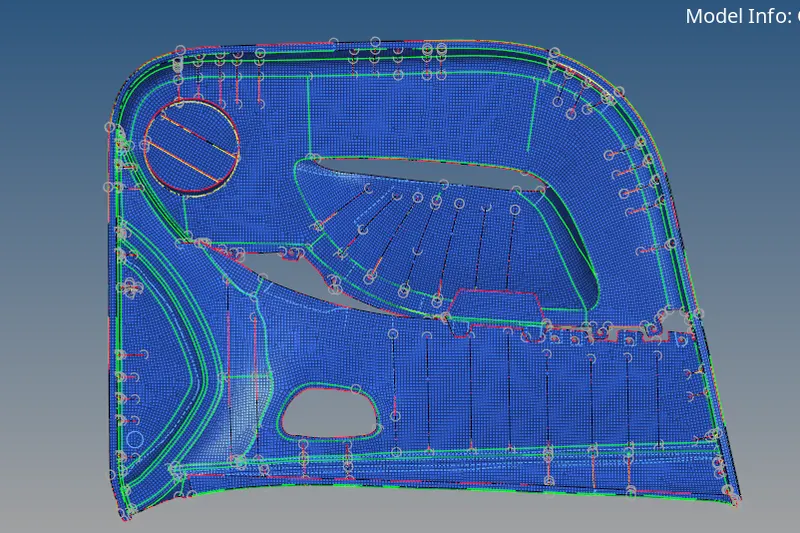
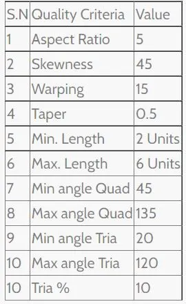
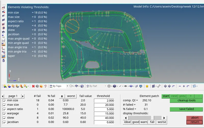
The obtained mesh fails for quality criteria which can be corrected by remeshing with 2D > rebuild mesh ad select edit criteria. A window is opened where quality criteria requirements can de given. Then, select the elements and click rebuild. If the mesh still fails select the elements and remesh it.
Also check for connectivity by Tool > edges, select the elements and click preview equivalence. This can be corrected either by clicking equivalence in the same menu or by manually through 2D > replace and selecting the nodes to replace.
To assign thickness:
Since there are surfaces and many ribs with varying thickness, arrange the elements with same thickness to the same component by Tool > organize, select the elements and click move.
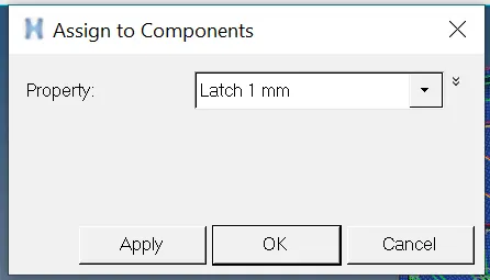
Then create property cards for all the thickness and assign it to the respective components.
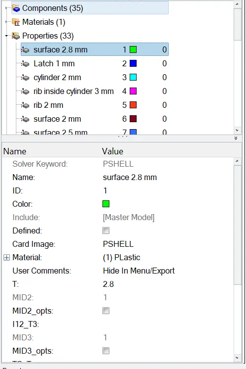
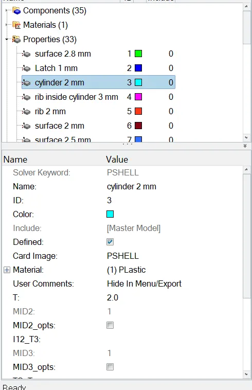
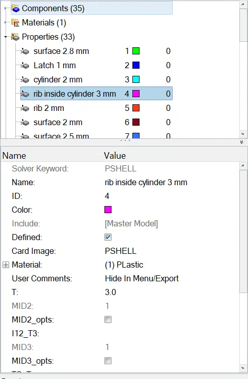
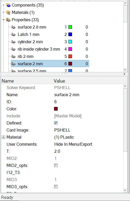
Give thickness for each and every components having varying thickness
after that assign the property to the component ,
RESULT:
The given is meshed property with the given quality criteria requirements and the correct thickness is assigned the respective elements.