Week 12:Project-1-Meshing of Door Inner Panel Challenge
AIM:
Follow the Quality Criteria and mesh the following component and assign thickness:
Target Element Length = 4 Units
| S.N | Quality Criteria | Value |
| 1 | Aspect Ratio | 5 |
| 2 | Skewness | 45 |
| 3 | Warping | 15 |
| 4 | Taper | 0.5 |
| 5 | Min. Length | 2 Units |
| 6 | Max. Length | 6 Units |
| 7 | Min angle Quad | 45 |
| 8 | Max angle Quad | 135 |
| 9 | Min angle Tria | 20 |
| 10 | Max angle Tria | 120 |
| 10 | Tria % | 10 |
PROCEDURE:
- Download the model from the project assignment.
- Check the format of the model given. And import the model by selecting the proper format.
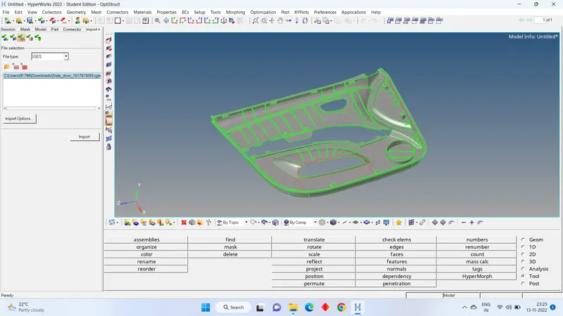
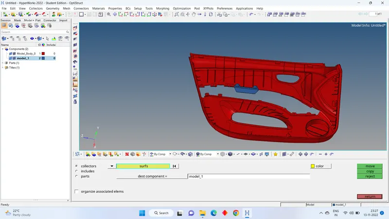
- Check the model if any other component present in that. If any present of other component in the given separate it by using the organize tool.
- For that go to MAIN MENU TOOL > TOOLS > ORGANIZE > COLLECTOR > ELEMENTS > NEW COMP IN DEST COMP > MOVE.
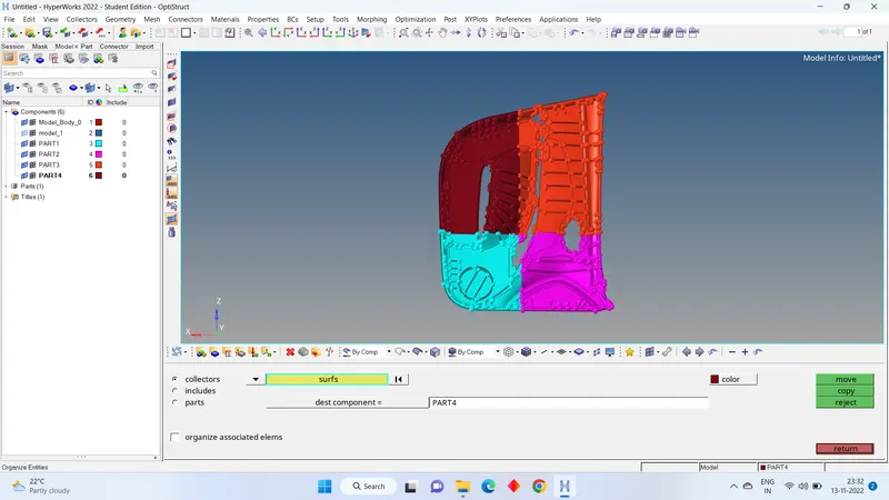
- Check the model if you find complex shape divide the model into 4 number of parts.
- For that go to GEOM > SURFACE EDIT> TRIME WITH SUFACE/PLANE > SELECT THE SUTAFCE > AXIS > BASE > TRIM
- Now take the mid surface one by one. If possible, take mid surface by automatic mid surfacing.
- For that go to GEOM > MID SURFACE > EXTRACTION OPTIONS > SKIN OFFSET > AUTO EXTRACTION > SELECT THE SURFACE > EXTRACT.
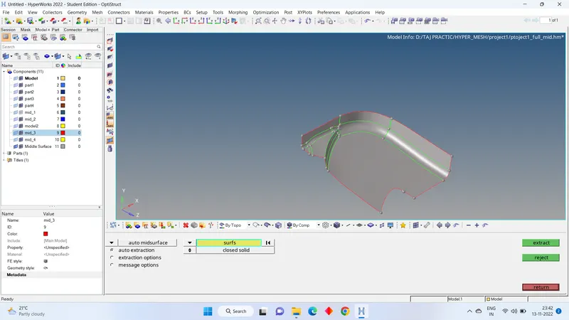
- Check the mid with parent component if its given good we can continue. But I found wrong mid.
- So, I went with manual mid surface for that go to GEOM > SURFACE EDIT > OFFSET > SELECT THE SURFACE > DUPLICATE > MAKE CURRENT AS REQUIRED > GIVE OFFSET DISTANCE > OFFSET.
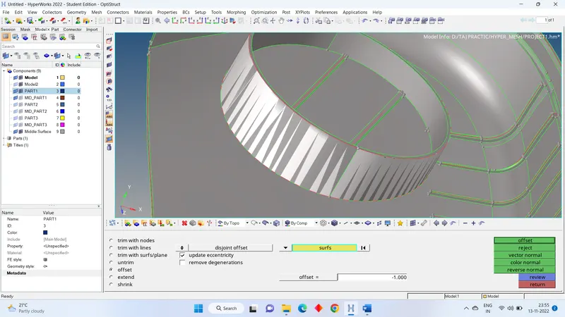
- And some parts like ribs which we can take mid very easily auto mid by selecting two surfaces.
- For that GEOM > MID SURFACE > AUTO MID SURFACE = FINAL EDIT TOOLS > SELECT THE SURFACE > EXTRACT.
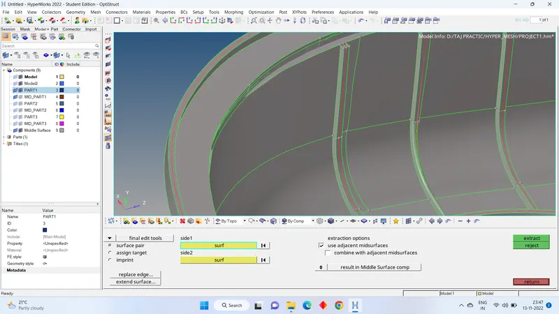
- If we observe the ribs not connected to the main mid surface. So, we have to extend to the main surface.
- For that go to GEOM > SURFACE EDIT > EXTEND > SELECT THE EDGE > SELECT THE SURFACE TO BE EXTENDED > EXTEND.
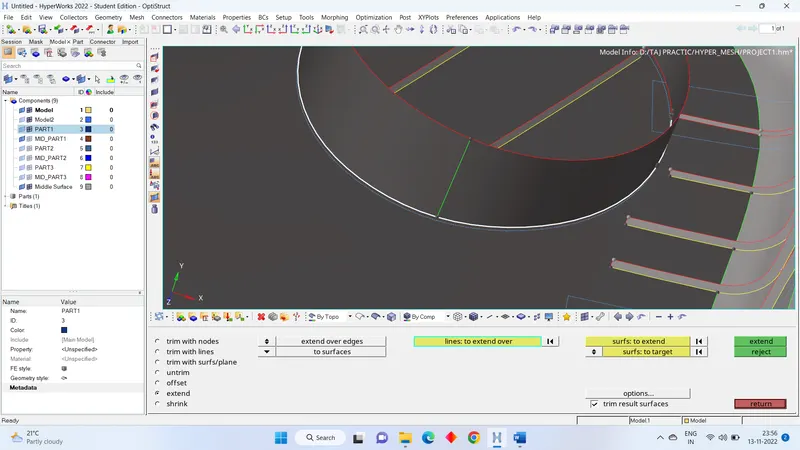
- Complete the model by taking the mid surface by using manual or auto mid tools.
- Before meshing it always preferred to give the quality criteria. To give quality criteria to MANU BAR > PREFERENCE > CRITERIA FILE SETTING > CHANGE THE VALUES OF QUALITY PARAMETERS ACCORDING TO THE REQUIRED > APPLY > OK.
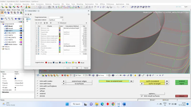
- Now go to 2D > AUTO MESH > SELECT THE SURFACE > ELEMENT SIZE =5 > TYPE = MIXED > MESH.
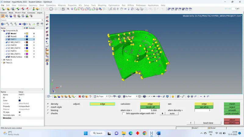
- Now change element colour mode to by element quality. Here we can see how many numbers of elements are failing due to parameters.
- I have observed the many elements are failing due to quality.
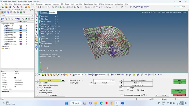
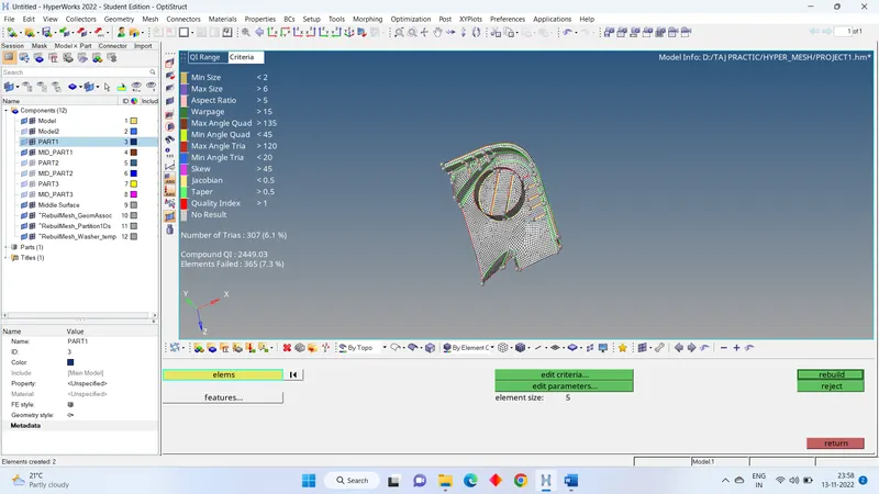
- We have best option to correct most of the element quality with help of mesh rebuild.
- For that go to 2D > REBUILD MESH > SELECT THE ELEMENTS > REBUILD.
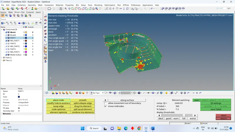
- Go to 2D > QUALITYINDEX > CLEANUP TOOLS > use the tools like PLACE NODE, ELEMENT OPTIMIZE, DRAG TRIA ELEMENT and SWAP EDGE.
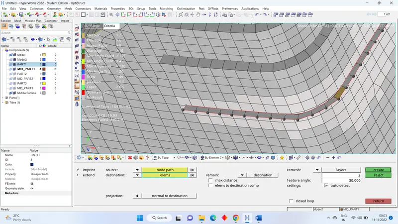
- we can also use some extend option to join the mesh elements for the ribs.
- Before using this option, we should mesh on both surfaces.
- Now go to 2D > MESH EDIT > IMPRINT > SOURCE= NODE LIST > SELECT THE NODES > DESTINATION = ELEMENTS > REMAIN = DESTINATION > CREATE.
- It’s time to assign the thickness property to mesh. We can directly go for auto mesh thickness assign.
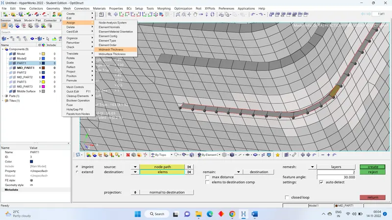
- MANU BAR > MESH > ASSIGN > MID MESH THICKNESS > SOLID MESH = COMPONENT > MID MESH > THICKNESS > THICKNESS OUTPUT > PROPERTY ON COMPONENTS > CALCULATE THICKNESS.
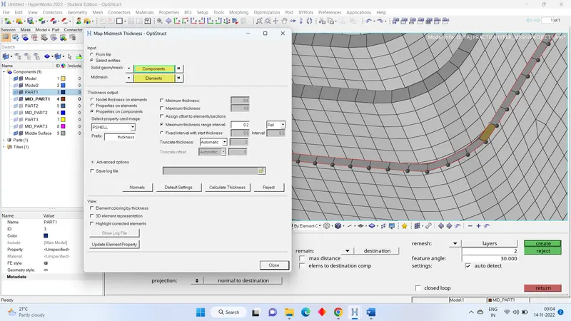
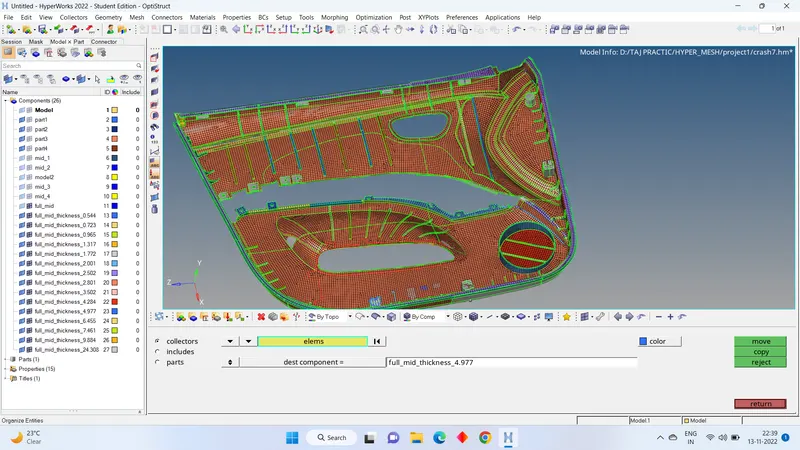
- We could see that it has not given property thickness properly so, we have to change the thickness of elements.
- For that go to TOOLS > ORGANIZE > COLLECTORS > SELECT THE ELEMENTS (which we want to change) > SELECT THE COMPONENT (which has the proper thickness) > MOVE.
- Save the file.
LEARNING OUTCOMES:
1. use of mesh edit option like extendeding the mesh upto the surface.
2. making the T joints in mesh.
3. Assign of auto thickness and correcting the thickness.
4. taking the mid surface for complex shapes.