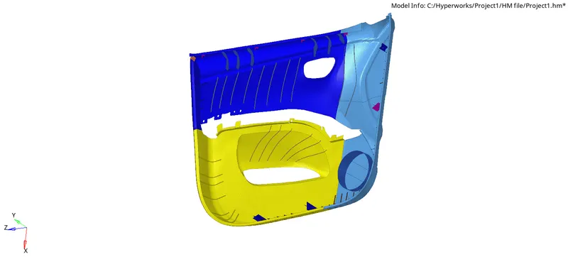
Week 12:Project-1-Meshing of Door Inner Panel Challenge
AIM: To create a Shell structure of 2D to a mesh of the Car Side door inner panel by eliminating geometrical errors and considering the given element criteria using Hypermesh.
Objective:
- To create a midsurface
- Clean up the geometrical errors
- Applying the Element criteria
- Selecting the Surface to be mesh
- Clearing the quality criteria elements
Introduction:
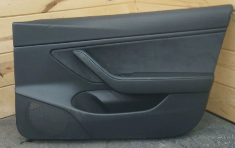
Car Side Door Panel:
The Car inner side door panel is made of Plastic Components. Mostly the inner panel is made of acrylonitrile-butadiene-styrene(ABS) Polycarbonate alloys, Polypropylene.
Properties of Car Door Panel:
High Weathering resistance
High Strength and toughness up to 140C
High Rigidity
Good Impact Resistance
Below is the Reference for the Car Side Door Panel:
Method We Use:
Finite Element Analysis:
The FEA is a numerical technique for obtaining an appro solution to a variety of engineering problems for a complex structural design.
Perform FEA is done in 3 Phases:
Pre-Processing
Solution
Post-Processing
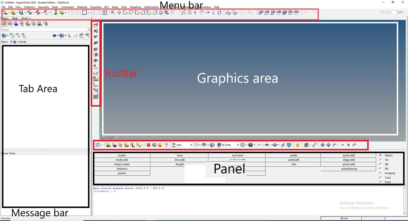
Here in Hypermesh, it is a Pre-processor based software.
The ultimate goal of the FEA is to deploy appropriate finite element mesh, and assign a suitable material ID and Boundary conditions, widely used tools are Hypermesh & ANSA, here I'm going to use Hypermesh as my tools to perform the mesh.
Checking of Quality Criteria:
Quality Criteria and mesh the following component and assign thickness:
Element Quality Criteria:
Target Element Length = 4 Units
| S.N | Quality Criteria | Value |
| 1 | Aspect Ratio | 5 |
| 2 | Skewness | 45 |
| 3 | Warping | 15 |
| 4 | Taper | 0.5 |
| 5 | Min. Length | 2 Units |
| 6 | Max. Length | 6 Units |
| 7 | Min angle Quad | 45 |
| 8 | Max angle Quad | 135 |
| 9 | Min angle Tria | 20 |
| 10 | Max angle Tria | 120 |
| 10 | Tria % | 10 |
Procedure:
To do FEA:
Import the IGES model to the Hypermesh
CAD geometry clean-up and topology errors
Extract the Mid-surface
Defeaturing the component
Shell Element
Create a Mesh
Assign Properties and Thickness
Import:
Load the model into the Hypermesh
From the imported file we can see so many features such as Ribs, Locators, etc. So that this component has different thicknesses on each feature.
Geometry Clean-up:
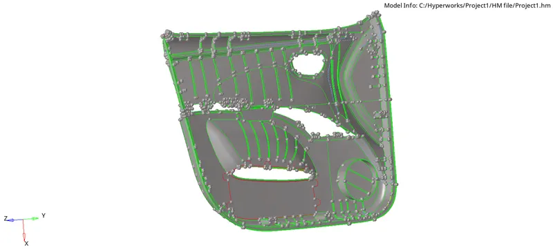
In this step, the model undergoes a geometry checking to ensure any kinds of distorted errors, in this all the collapsed faces, Cracks, Free Edge need to be cleared.
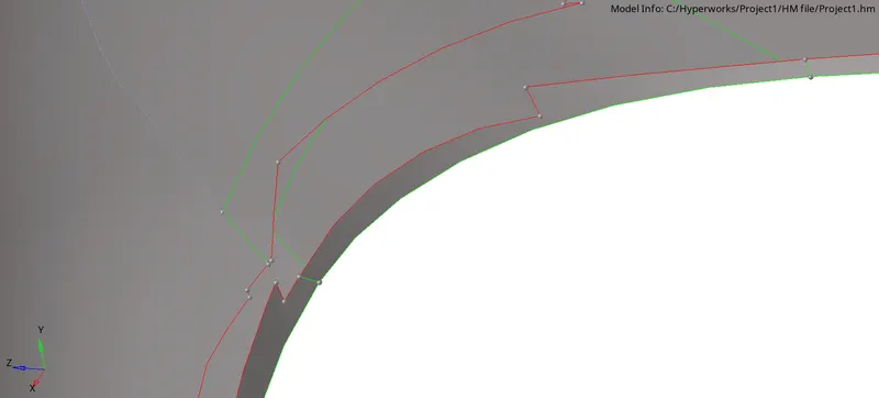
Tools used to correct the Topologies Errors:
First, check for Equivalence for that -> Equivalence (multiple edges at a time) Search surfaces for pairs of free edges and combine them into shared edges.
The next step is to Toggle the surface, -> Select an edge: equivalences with other free edges found within a user-specified tolerance
Check for any distorted surface, then use Replace option, -> Replace (1 edge pair at a time) Select 2 edges to equivalence together. Control which edge to retain and which to move.
To create a missing surface in the component -> Geom ->Surfaces ->Ruled or Geom-> Quick edit -> filler surface or 2d -> spline -> surfaces only (to create missing surfaces).
Defeature:
To achieve the minimum element for the given criteria files we have to eliminate the surface which is below the minimum element sizes here the minimum value is 2, so to defeature the surface, select the Goem -> Defeature -> Surf -> enter the value minimum and maxi values in it, then select it and surface will be highlighted to deleted, delete that particular surface.
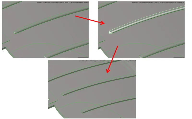
Splitling up the Surface:
To perform a Midsurface extraction we have to split the surfaces because it has different thickness, to get it better we have to split it.
To split up the surface, Geom -> Trim with surf/planes -> Select the surface -> select the node -> Create.
Then the split happens in it.
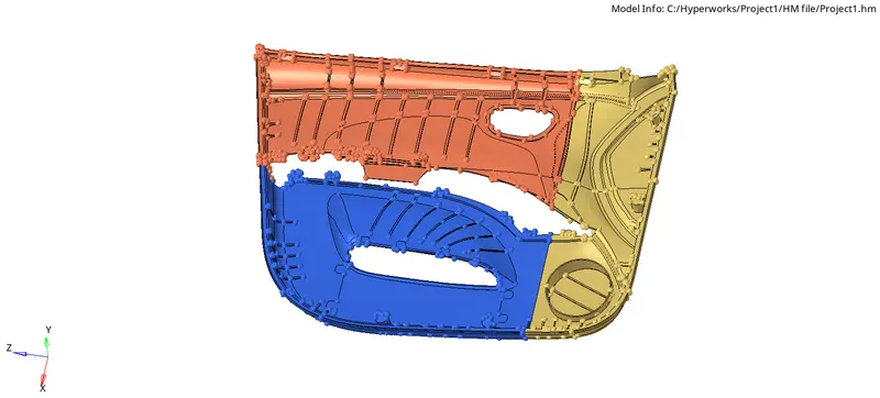
Extraction of Midsurface:
Due to differences in thickness, I used the Manual Offset method in it.
For the manual offset method, Create a Component -> Geom -> Surface Edit -> Select the Surface -> Give the Offset value of 1.4 due to 2.8mm being the overall thickness of the component.
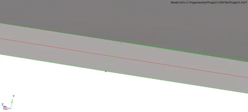
Redline refers to the Midsurface of the component.
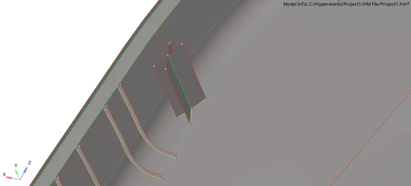
Midsurface above 6mm:
Thickness is above 6mm, we can extract it by using the midsurface option.
For that create a temp node where to create a cross-section surface, then create a line by joining the lines.
Before:

After:
Midsurface for Improper surface:
For all ribs extraction of mid-one file final edit tool from Midsurface.
To capture the improper surface, there is a method to capture it, by using Final Edit Tools
Select the method to offset as Final Edit Tools -> Select the surface -> Offset.
Select a surface that represents one side of the solid.
Select a surface that represents the second side of the solid.
Select extraction options accordingly to define which surfaces to take into account when constructing a midsurface.
By default, only two surfaces that are selected with the side1 and side2 surf selectors are considered.
To take into account offset directions of the adjacent pre-existing mid surfaces, select the use adjacent mid surfaces checkbox.
To allow modifying pre-existing adjacent mid surfaces, select the combine with adjacent mid surfaces checkbox.
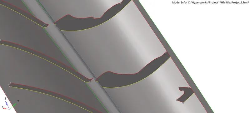
Once extracting the shell Surface of the complete components, now we have to create a mesh in it, due to the split of the surface each component needs to mesh separately so that the flow of mesh will be good.
To start up with the mesh, we have to implement the quality criteria file to it.
For 2D mesh, 2D -> Automesh -> Select the surface -> Create
Select size and bias and select mesh size which is Target/Average length 4. Use the Size and Bias subpanel to perform size and bias meshing, a flexible and powerful meshing method. A minimum of inputs are required for the element criteria settings. The algorithm options set preferences on how to handle certain situations when encountered in the geometry. When using existing finite elements as the basis for mesh generation, feature recognition settings allow the mesh to break up the areas defined by the selected elements into logical groupings with mesh controls set for each group boundary.
Select the type of mesh as mixed (Quad, Tria, mixed, R tria, etc) and clock on alignment and size in order to get proper mesh near features.
click on the mesh or middle mouse button
Part 2:
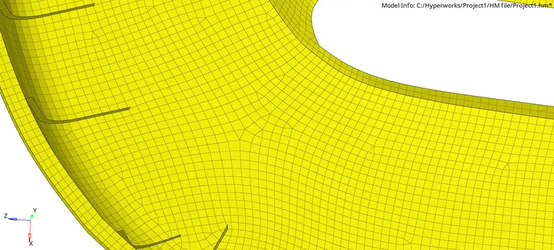
Part 3:
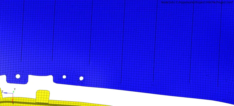
Part1:
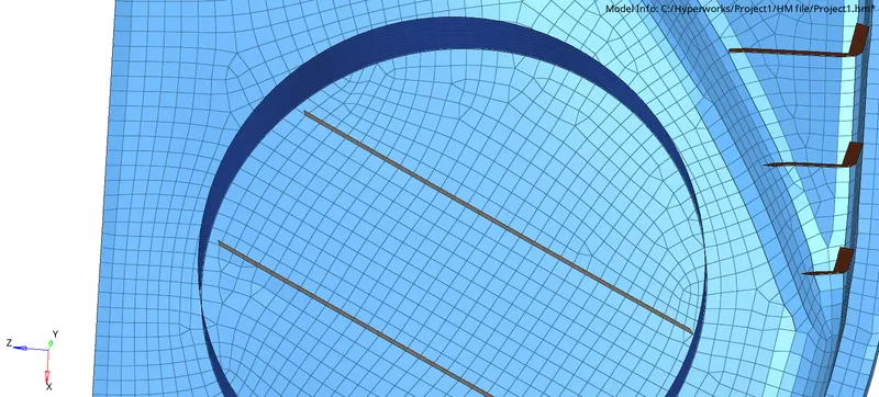
Modify mesh flow by changing surfaces to elements and selecting the elements. Make sure that while doing mesh all the element Quality criteria must be satisfied. Avoid maxim opposite trias.

To get a proper mesh flow even after the auto mesh, we can use the "Remesh option" to enhance the mesh flow
Before:
Before rebuilding the mesh
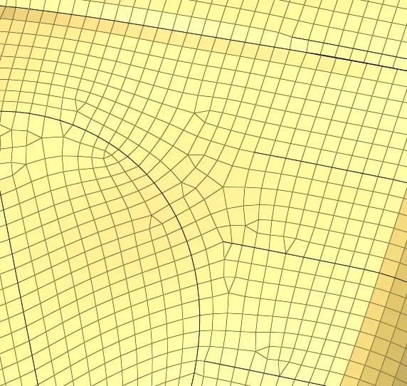
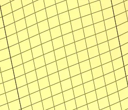
After:
After rebuilding the mesh
After Completing the Mesh:
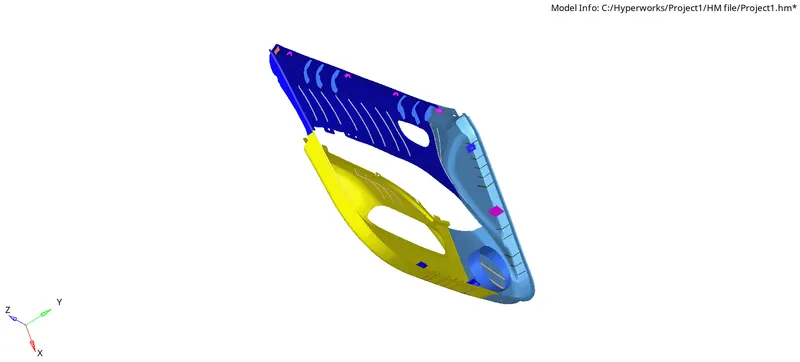
Creating properties and Thickness assigning: Not only properties we can create components, material, Cross sections, etc by right click on the Tab area and selecting the requirement.
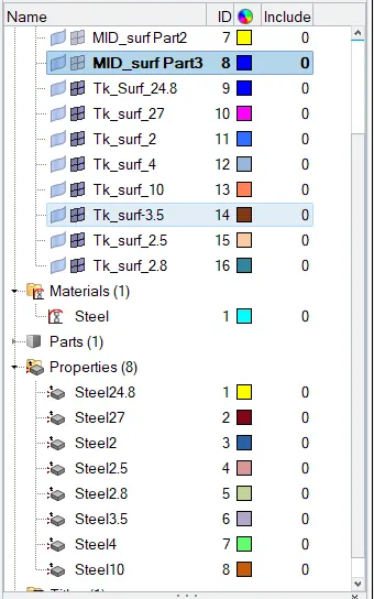
Before creating properties we need to create components for elements as per the different thicknesses. Right-click on the Tab area and select component to create components. Shows the components as per the thickness. If we have varying thicknesses (taper). Then divide that region with respect to mesh flow and assign thickness value from maximum to minimum with equal intervals. Here i have used Steel as my material.
To create Material -> Create -> Material -> Steel -> assign
Create property as per the thickness of the component. To create -> right-click on the Tab area and select property to create properties.
a.select property, we can see the properties in the tab area.
b. Click on the property and rename, change the thickness, select material, card image and etc. for each component we need to create property shown in the fig6.3
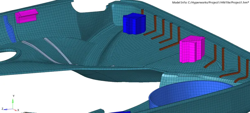
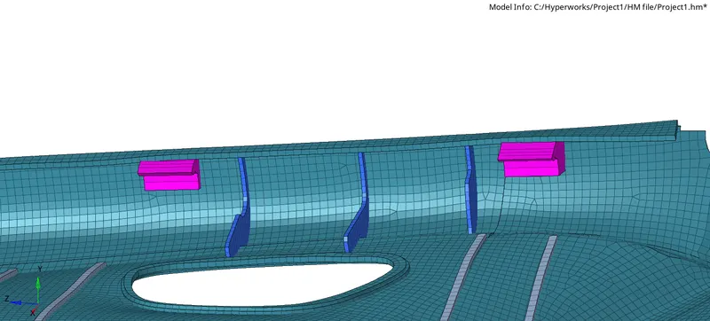
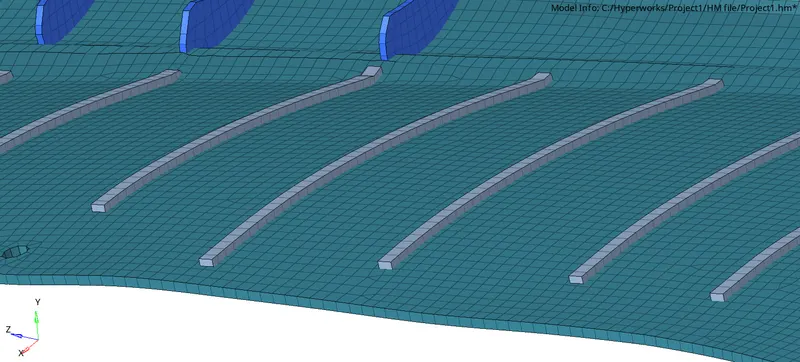
After assigning a Properties:
Find Free Edges:
Use the Edges panel to find the free edges in a group of shell elements, and find "T" connections in a group of shell elements. Free edges are defined as a pair of nodes identifying an element edge that is not shared with another element. Free edges are normally found around the outer perimeter of a part or around openings within the part.
Free edges found in your model are displayed as red plot elements in their own component called edges. Free edges within a field of elements typically indicate a discontinuity within the mesh. Such discontinuities may be intentional, such as crack modeling for durability simulation, or unintentional, due to geometry discontinuities, meshing methods, or component boundaries. In cases where the mesh has a discontinuity, there will typically be more than one node at approximately the same location in space. Such nodes are called "coincident". You can use equivalence to remove the coincident nodes, based on a search tolerance that you specify.
Steps to follow:
a. Go to tools>Edge
b. Select the elements whose associated edges you wish to find.
c. Specify a spherical search radius around each node in the selected component or group of elements. If multiple nodes are found within this search tolerance they are considered coincident and can be resolved with the equivalence function. tolerance is approximately 60 to 70 % of the thickness
d. Click on preview equivalence. and equivalence to join nodes.
e. Click on find edges to see the free edges in Red color for mesh
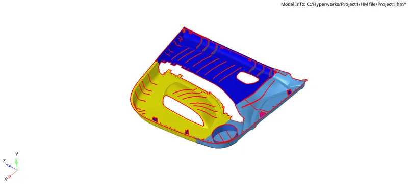
RESULTS:
As required the Shell (2-D) mesh is done Successfully for the Side Door Panel model by eliminating geometrical errors and considering the given element quality criteria also assigning thickness using Hypermesh.