Week 12:Project-1-Meshing of Door Inner Panel Challenge
Objective :
- Obtain the proper mid surface of the given side door panel.
- To mesh the given side door panel with a target element size of 4mm and also element should pass the all quality criteria which was mentioned as per the requirement.
- finally, apply the thickness to the component according to their varied thickness.
Mesh quality criteria:
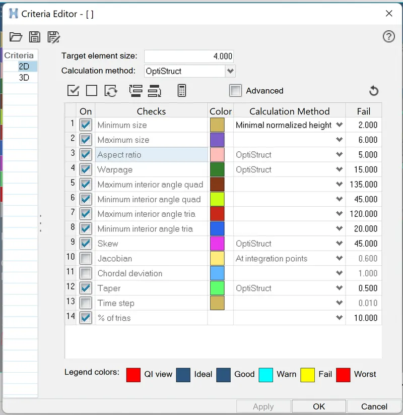
| Sl no. | Quality criteria | value |
| 1 | Aspect ratio | 5 |
| 2 | skewness | 45 |
| 3. | warpage | 15 |
| 4. | taper |
0.5 |
| 5. | max.length | 6 |
| 6. | min. length | 2 |
| 7. | max.angle quad | 135 |
| 8. | min.angle quad | 45 |
| 9. | max.angle tria | 120 |
| 10. | min.angle tria | 20 |
| 11. | tria% | 10 |
1. Importing the model is the first procedure of the process. After importing the model check whether it has solid or not if solid is present delete the solid.The commad is delete(F2)> solids.
2. next is to extract the mid surface for the given component. The component has a different thickness because it is a plastic component. based on that we extract the mid surface manually by using the offset command. Surface edit(shift+F9)> offset.
3. before going to get mid surface we have to split the surface to get easily mid surface OR we can get it directly in this project I worked directly to get mid surface. In the fiilet regions the defeature has been takes place particularly in the rib regions.Geometry > Defeature > Surface Fillets.
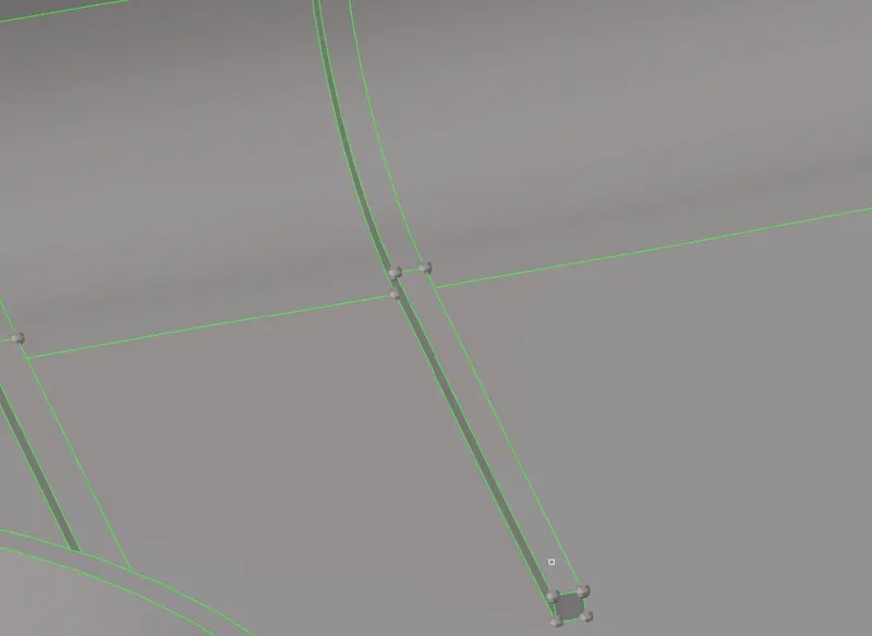
4. In the rib regions we can get mid surface by multiple command like offset option.Another one is in the mid surface > final edit tools> surface pair > select surf1>surf2. For joining we used imprint option.

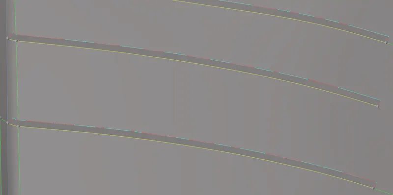
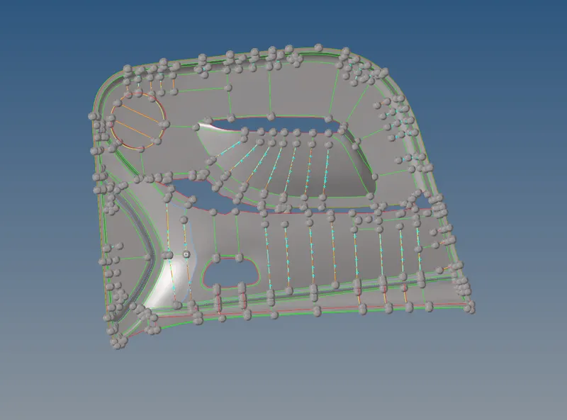
5. We must clean up the midsurfaces after they are formed to make sure that the mesh's minimum length is met for all of its components. Additionally significant is the prevention of trias wherever possible through the manipulation of surface properties to enable high-quality mesh. Various quick edit tools, including as the toggle, replace, and split-surface node options, are used to do this. You may get to these tools by selecting Geometry > Quick Edit.
6. Before entering to meshing we have set the given quality criteria in preferences> criteria file setting.
7.After that we can go for the meshing process in a specified region with a proper mesh flow. The mesh flow is maintained throughout the component for the proper result. The target element size is apply in the 2d > automesh(F12). Then select the surfaces which are to be meshed.

8.After meshing, we have to take care of tria elements which are falling on feature lines rotating quads and we have segregate them.
9. the tools that are used to modify the elements are 2d>quality index. In this, we can use drag trias element optimize and split quads are used. We also used edit elements(F6) and replace (F3).
10. After the editing of the elements we have to smooth option Smooth(shift+F12).
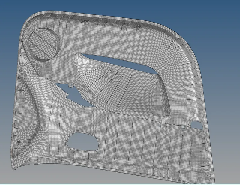
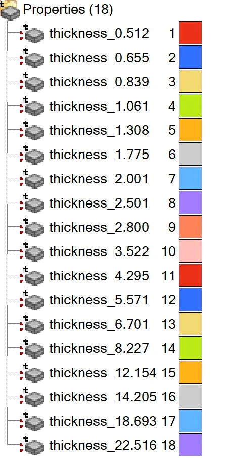
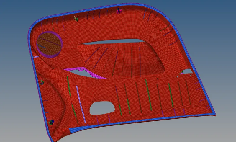
11. after the meshing we have to apply the thickness to the component. In this project we used a automatic applying of the thickness because it is aplastic component having a diiferent thickness in different regions. The command used is mesh> assign > midmesh thickness.
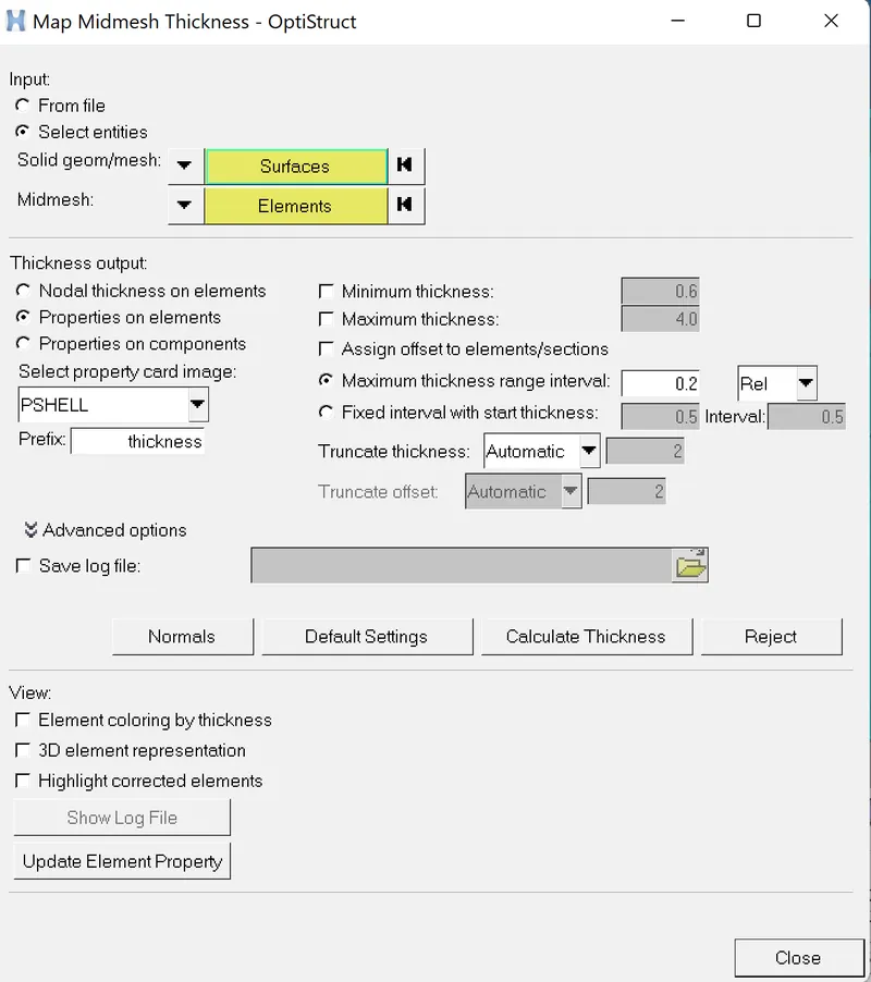
For the surfaces we have to select parent geometry surfaces and elements from the midsurface component. Finally, click on calculate thickness.
If there are any free edges, we can link them with the help of the equivalency tool in the same section. Such locations are discovered by the preview equivalence option within the search radius (tolerance) of a node that is unconnected to another adjacent node. By linking them, the "equivalence" proves what should be clear.
14.Finally, we can check to see if there are any duplicate elements through the Tools > Check Elements and selecting 'duplicates', with all meshed components on display. If duplicates are present, they can be 'saved' by clicking the 'save failed' option. Then we can go to the mask option and 'retrieve' the duplicate elements, mask them and then mask reverse to mask all the other elements. Now, with just the duplicates visible, we can go ahead and simply delete them.
15.Lastly we can see the thickness by ticking the 2d traditional and detailed element representation
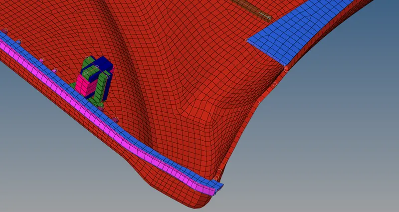
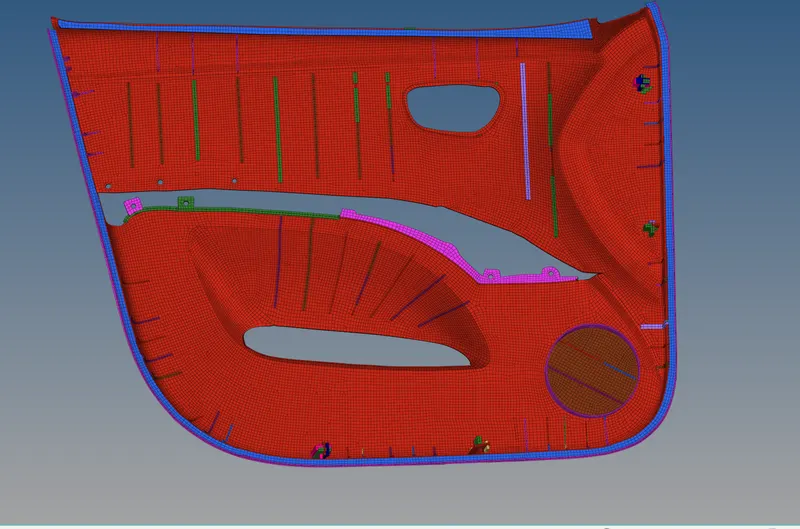
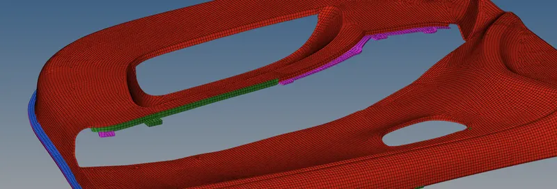
Final model captures:
Result:
The given side door panel model was meshed according to given quality citeria and also with good mesh flow. The model was applied with different thickness by midmesh method, because it is a plastic component.