Week 12:Project-1-Meshing of Door Inner Panel Challenge
Aim :
- The meshing of the Door Inner Panel
Objective :
- with the Follow the Quality Criteria and mesh the following component and assign thickness:
Target Element Length = 4 Units
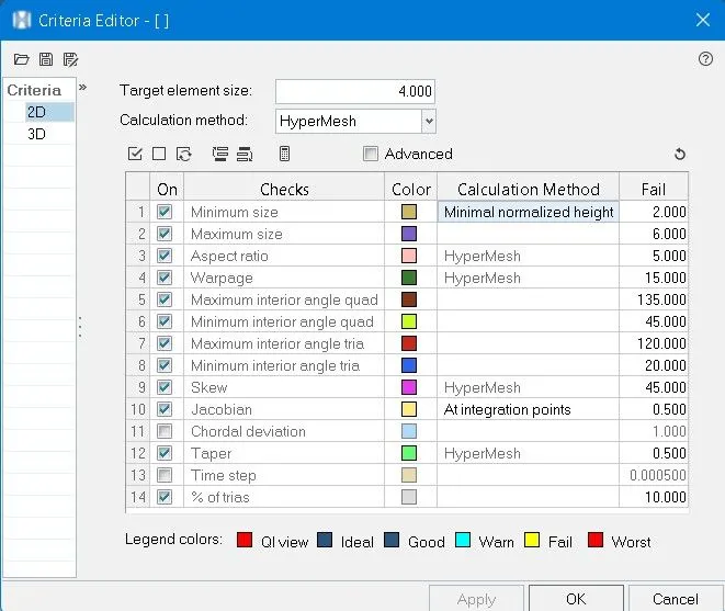
S.N Quality Criteria Value 1 Aspect Ratio 5 2 Skewness 45 3 Warping 15 4 Taper 0.5 5 Min. Length 2 Units 6 Max. Length 6 Units 7 Min angle Quad 45 8 Max angle Quad 135 9 Min angle Tria 20 10 Max angle Tria 120 10 Tria % 10
Procedure:
import the side_door_panel.hm file into the hypermesh
File >> open >> browse the file and open.
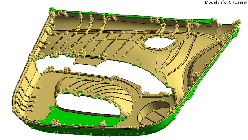
after importing the geometry we can see so many ribs, locators, etc. So this component has different thicknesses for the different features.so rather than going to automidsurface we go for creating the offset for the surface.
then the quality criteria as per given the problem.
preferences >> criteria file settings
Then Click on By Topology.
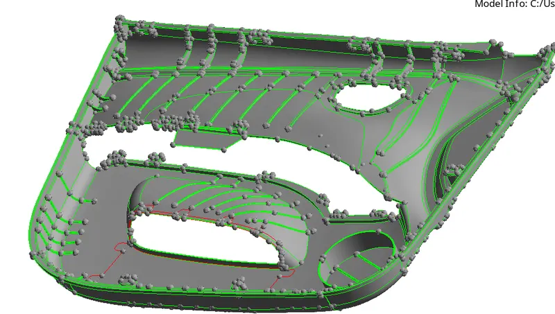
Then repair the surface using the tool in the Quick edit panel.
toggle edges, replace points, add points, etc.
Geometry >> Quick edit
Then using defeature remove fillet surfaces.
Geometry >> defeature >> Surf fillet
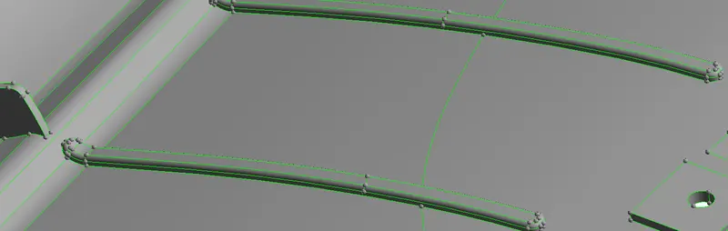
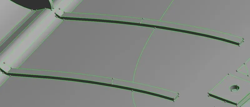
as the fillet are less than 4 units it fails for minimum element criteria so removed all the fillets as shown above. Such a way removed all the fillet.
Then we split the whole component into four components.
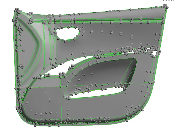
Then we worked on separated components and created the midsurface by duplicating and offsetting surfaces in the middle.
first the distance between the surfaces and created the middle point and measured distance between the middle point and outer point.
F4 - Geometry >> distance >> two-point
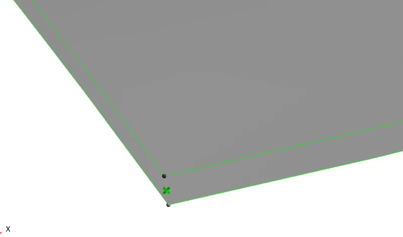
selecting the surface duplicating them and offsetting them as the measured distance.
Geometry >> Surface edit >> Offset >> Enter the offset distance
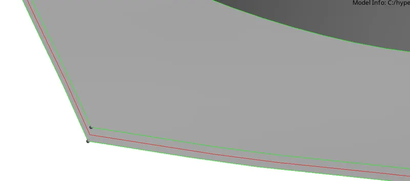
The same procedure is done for all the surfaces to create the midsurface.
creating the same midsurface for all the ribs.
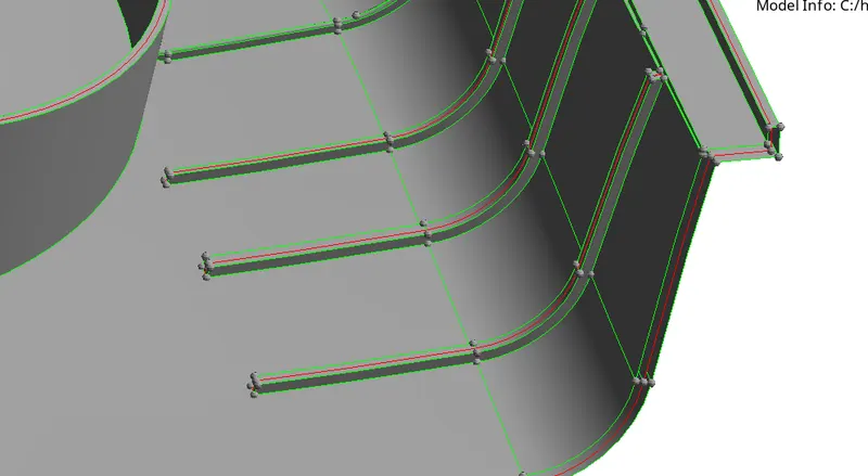
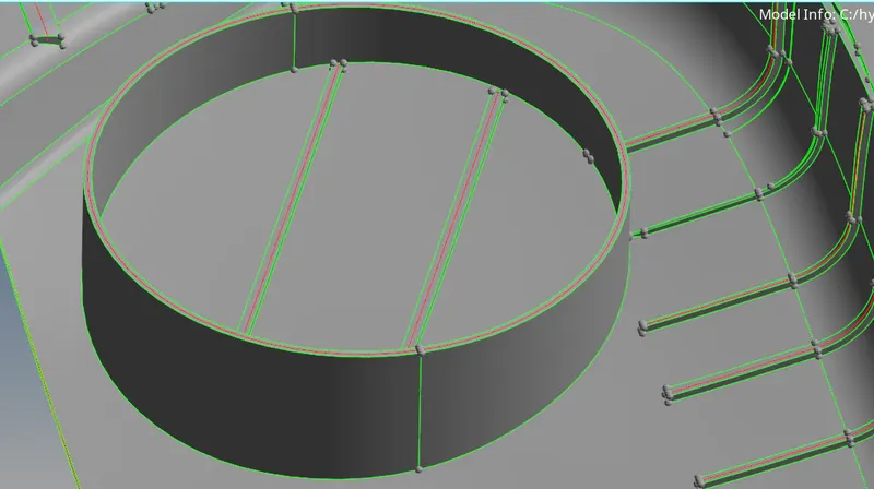
The same procedure was done for the ribs and surfaces.
as we created the offset for surfaces and ribs. ribs are not touched to the surface. the edges will show in red color which means free edges. Edges must be yellow in color.
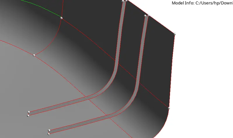
for that first, we extend surfaces and trim them and delete the extra surfaces.
first, drag the surface along the vector
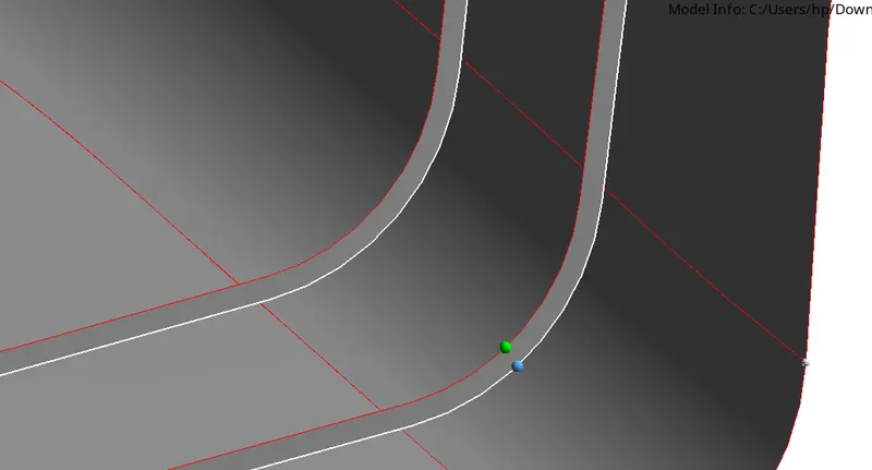
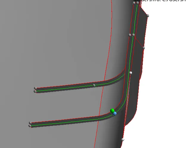
Geometry >> surface >> drag along with vector option (select the line and give the distance)
Trim the surfaces using the self-intersecting surface option
Geometry >> surface edit >> trim with surface/plane >> self intersecting surface (select the intersecting surface)
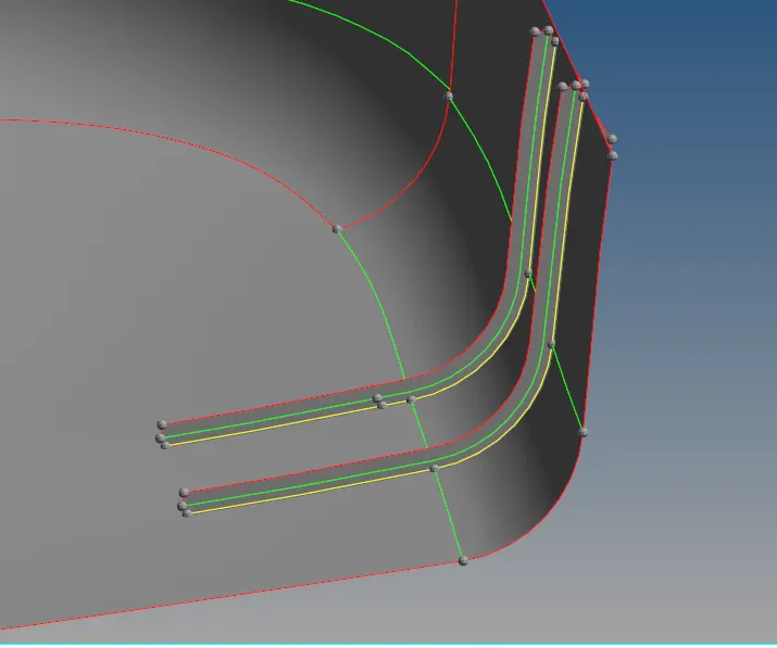
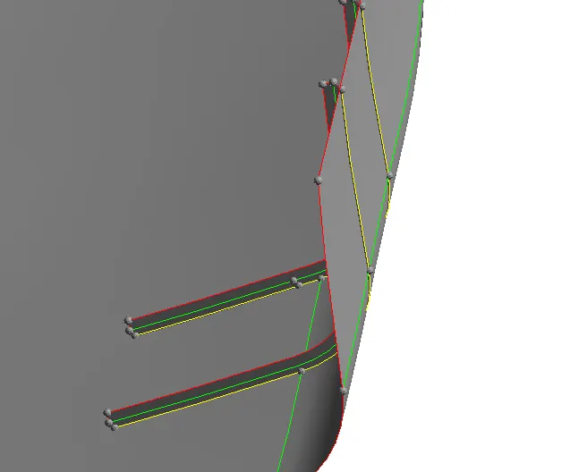
them delete the extra surfaces
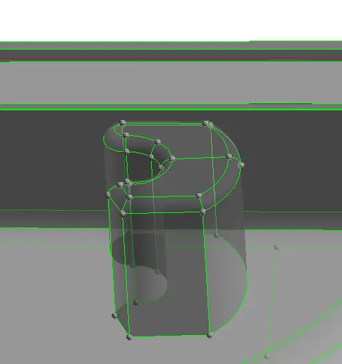
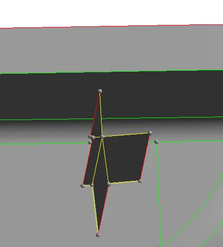
as we know The area which is having more than 6mm thickness should not model in 2D.for such surfaces we model as shown below.
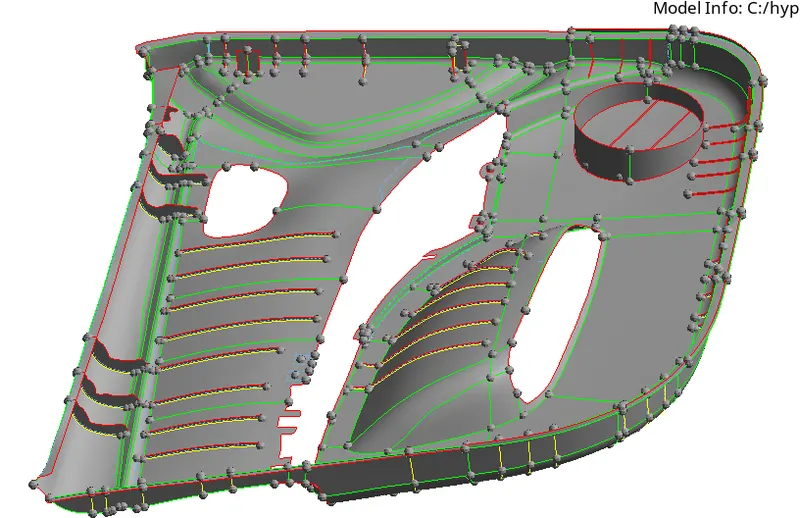
Finally offsetting all components and ribs we get the below component (midsurface)
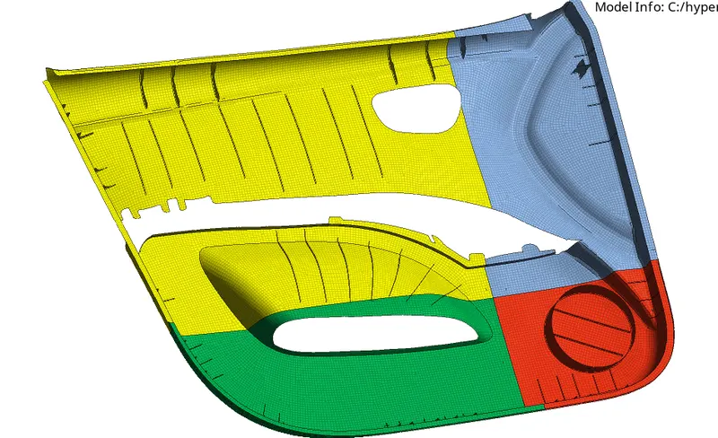
Then mesh all the component
2D >> automesh >> mesh (target element size as 4 and mesh type as mixed)

as the we meshed for splited component we have check the connectivity and need to connect the nodes using the replace tool.
2D >> replace >> (select the nodes to replace)

as the we meshed for splited component we have check the connectivity and need to connect the nodes using the replace tool.
2D >> replace >> (select the nodes to replace)
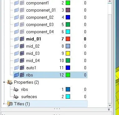
assigning the thickness to the ribs and surfaces
first we organize all the ribs in one component
then created the properties for rib and gave thickness as 2 and for surfaces as 3units
and assign those properties to the all components
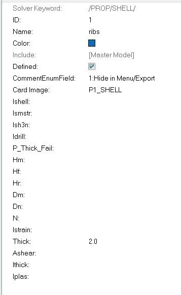
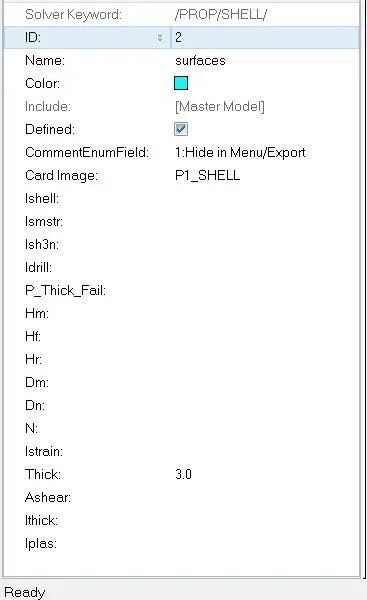
select the card image as shell and thickness is assumed
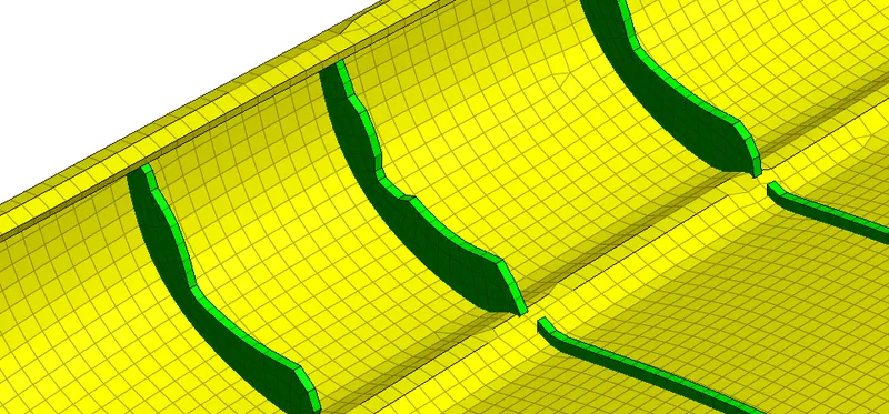
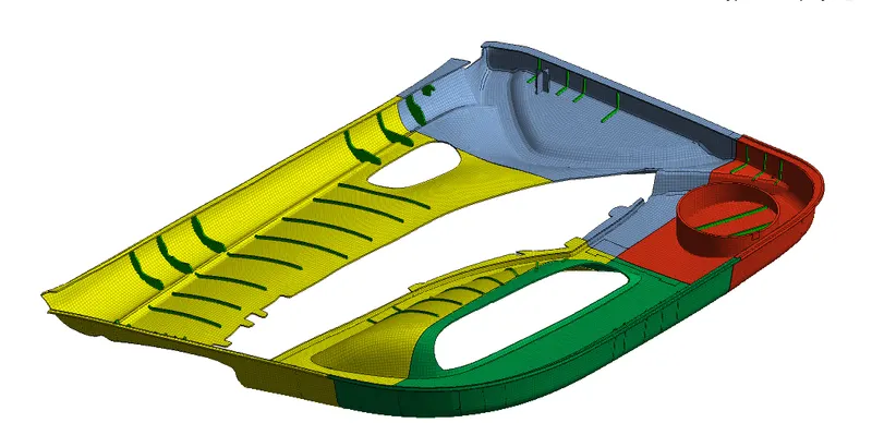
Result :
we created a midsurface and meshed the surfaces as per the given quality criteria.