Week 12:Project-1-Meshing of Door Inner Panel Challenge
PROJECT - 1
Meshing of Door Inner Panel
AIM:-
To perform preprocessing on the given car side door [Inner Panel] plastic component using hypermesh preprocessing software.
OBJECTIVES:-
- To generate the mid surface manually and do a geometry clean up on the component.
- To generate a mesh and to get a proper mesh flow on the given component with low tria concentration.
- To check the the elements quality according to the given quality criteria.
- To create a different collectors and organize the elements to that collectors to assign a thickness.
INTRODUCTION:-
Door panels serve as an interface between the interior of the car and the inner workings of the door, and between vehicle occupants and the door.
They are expected to meet a variety of design specifications regarding safety, aesthetics, and functionality. In addition, they are expected to continue the material theme of the dashboard and pillars while concealing intricate electrical and mechanical components for operating locks, windows, and other features.
The door panel has evolved from a simple two-part system of latch and simple winding mechanism to a more sophisticated enclosure.
Doors currently have an inner full-width panel consisting of electronic windows, central locking system, and speakers. These panels typically consist of a foamed core covered with either textiles or plastics.
Door panels were formerly made of cardboard with an upholstered interior finish of vinyl, leather, cloth, carpet or other materials for the decorative trim. Modern cars typically have door cards made of plastic, most often using injection moulding as well as incorporating other decorative materials.
The design should incorporate both the necessary service amount and the functional unit.The door panel typically incorporates other parts that contribute to the appearance, functionality, and ergonomics of the vehicle. These include armrests, switches or other controls for windows and the locking mechanism, convenience lights, audio speakers, storage compartments, and other features.
In most cases, the door card is attached to the car's door frame by visible screws and ones hidden behind decorative plugs or under the armrest, as well as spring clips.
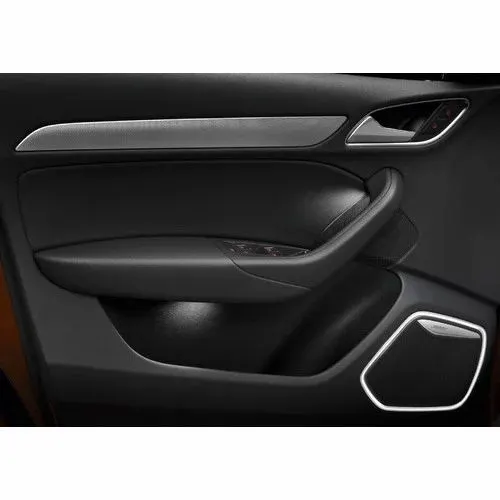
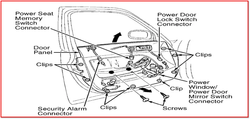
The Door Trim is a key component of the closure. Door Trim ia an interior component attached to the inner side of the door. These car door trim panels are made up of platic materials like Acrylonitrile-butadiene-styrene (ABS), ABS/polycarbonate alloys, polycarbonates, polypropylene, modified polyphenylene ether (PPE) and SMA (styrene-maleic anhydride) resins.
The model given to us to be meshed and the midsurface should be extracted manually cause the model given to us is a plastic and these plastic components will have varying thickness.So the midsurface should be extracted manually. This Door trim model will be analyzed in the solver,The crash analysis will be done for this model.
PROCEDURE:-
1) Importing the CAD File -
Firstly, We have to import given CAD geometry into hypermesh.
There are file formats like IGES, STEP, where we can import these file formats into any CAD,CAE Softwares. But in hypermesh we can only import three file formats like
IGES [Initial Graphics Exchange Specification].
STEP [Standard for the Exchange of Product Model Data].
Solidworks.
IGES, STEP, These two are standard file formats which are used most in industries.
File > Import > Import Model > File type > Open File > Import File.
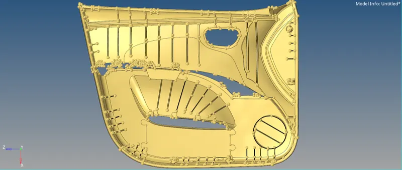
Switch to the topo mode and examine whether the solids exist in the component or not. If solids exist, It will be highlighted in the green color. Delete the solids cause we are doing 2d meshing on the component. We can find topo mode in the toolbar panel.
Delete (F2) > Solids > Select by box selection > Delete Entity.
2) Examine the Model -
Before working on the model, We have to check the geometry if there are any errors like Damaged Geometry, Free edges in unnecessary areas, Unnecessary points on the lines, Unnecessary Connections and connectivity error.
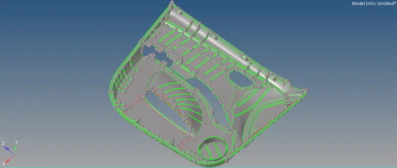
3) Checking Thickness -
Now go and measure the distance in every region. Because,The plastic component will be having varying thickness.
We are ensuring whether some regions of this component is having uniform thickness or not.
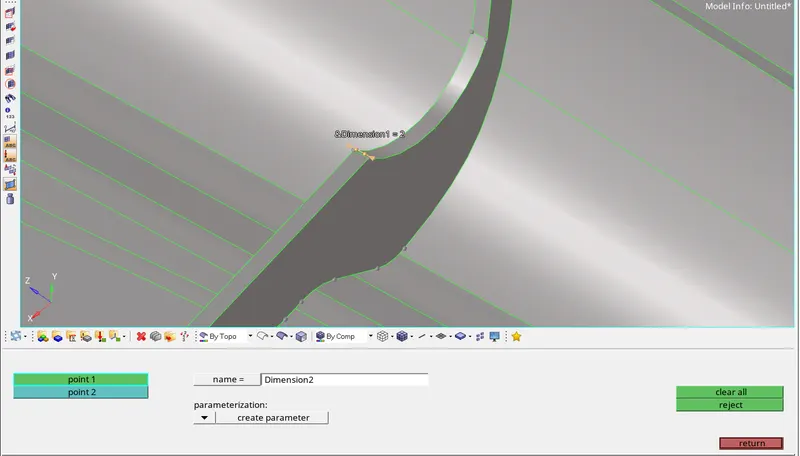
- Geometry > Dimensioning > Select the Point1 and Point2.
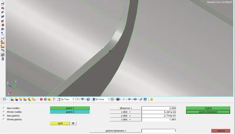
- Tool (F4) > Distance > Points > Select the Point1 and Point2.
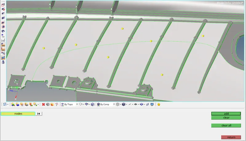
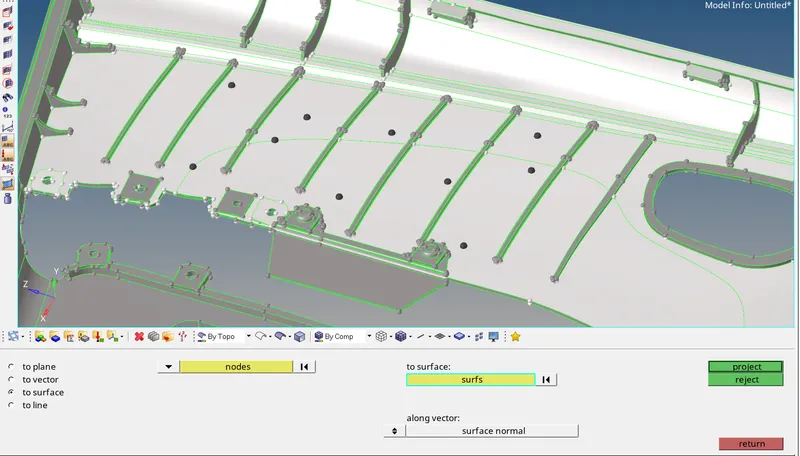
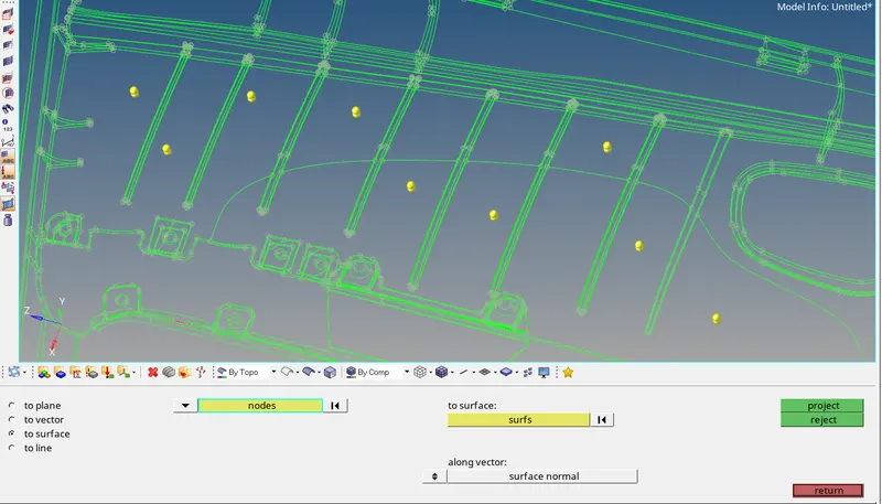
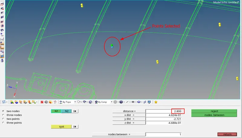
- Geom > temp nodes > select the surface to get it selected > click on various regions of the surface to create temp nodes > add. Now project these nodes onto the opposite surface faces using Tool > project > to surface > select the nodes > duplicate > select the opposite faces > project. Go to Geom > distance > two nodes > select point 1 and point 2.
4) Fixing Damaged Geometry in surfaces -
Deformed surfaces occur due to the following reasons like -
- Overlapping surfaces
- Connectivity issues
- Sometimes this issue occurs due to replacing the points multiple times
These issues can be rectified by using the tools called quick edit tool. We can fix the geometry by quick edit tool. There are some sub tools in the quick edit tool and those need to be mentioned here.
i) Geometry > quick edit > split surface node.
- Select two locations of the nodes to split the surface and then select an additional node to continue to split the surface.
ii) Geometry > quick edit > Split surf-line
- In this, select a node and select a line to split the surface, here the split will be perpendicular to the line chosen.
iii) Geometry > quick edit > Adjust/set density.
- After meshing a particular surface. We can adjust the mesh density by using this tool. While meshing we will increase the nodes to get a proper mesh flow. We can also increase nodes after meshing by using this tool.
iv) Geometry > quick edit > release points.
- Drag and select the surface, where we want to release the points. After releasing the points, The free edges will exist.
v) Geometry > quick edit > replace points.
- Move points from their current locations to the locations of other points, where we want them to replace it.
vi) Geometry > quick edit > add/remove points.
- Use window selection (with the left mouse button and right mouse button ) to add and remove any points within the selection box.
vii) Geometry > quick edit > add points on line.
- Specify the number of points that we wish to add to that line, and then select the desired line in our model.
viii)Geometry > quick edit > delete surface.
- Select the surface which we need to eliminate and delete it.
5) Extracting the Midsurface -
The midsurface has been extracted to the components which have less than 5mm thickness. We will be extracting midsurface for the sheet metal and plastic components. Before extracting the mid surface for every component, We should measure the thickness of the component and then we have to proceed to extract the mid surface. If the component thickness is less than 6mm then we will come to know it is a sheet metal component or plastic Component. For sheet metal and plastic components, Mid Surface extraction is a must.
- Check the thickness of the parent component -
The component given to us is a side door interior trim. This component is a plastic component,The plastic components will have varying thickness, We have to check whether it has varying thickness or uniform thickness. In some regions the plastic component will have varying thickness but in some regions it will have uniform thickness.
- Extract Mid the Surface Manually Using Offset -
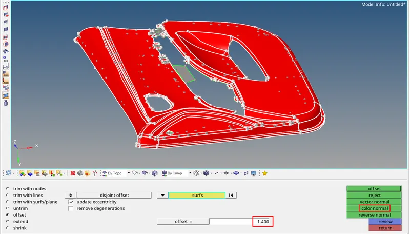
It Is observed that the average thickness of the plastic part base is 2.8mm.
Create a new component which will contain the midsurface and set it as the current component.
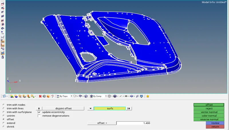
Geom > Surface Edit (Shift + F9) > Offset > surfs > by Face > Duplicate to Current Component > Offset = 1.4mm.
Vector Normal (If Outward) - Reverse Normal.
Blue indicates towards the screen or inward.
Red indicates away from the screen or outward.
If it shows Red, give it the reverse normal and it should show blue.
Color Normal (If Red) - Reverse Normal.
Color Normal (If Blue) - Offset.
- Extracting Mid Surface for the ribs -
We can extract mid surface for ribs by three methods -
i) By Using Offset Tool for the defeatured ribs.
ii) By Extracting Midline on the ribs and projecting it to the mid surface and creating a surface using ruled surface.
i) By Using Offset Tool for the defeatured ribs.
Geom > Surface Edit (Shift + F9) > Offset > surfs > by Face > Duplicate to Current Component > Offset.
First measure the thickness of the ribs and then select the one face and duplicate it to the current or original component and then extract the mid surface using the offset tool.
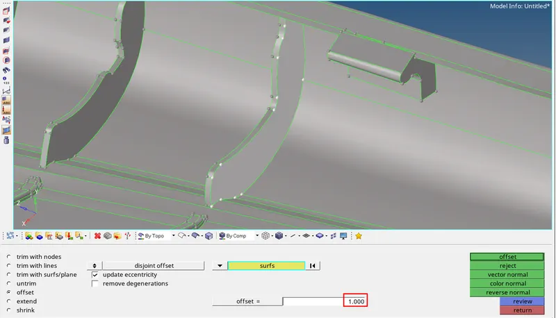
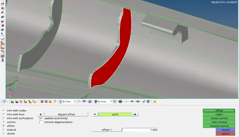
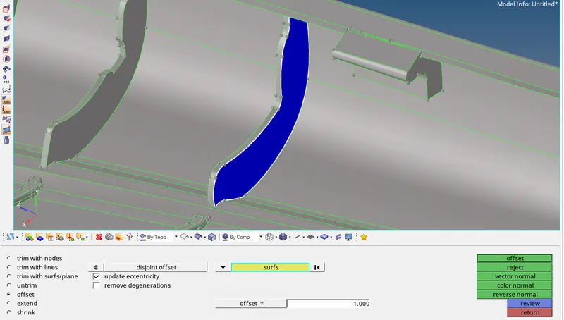
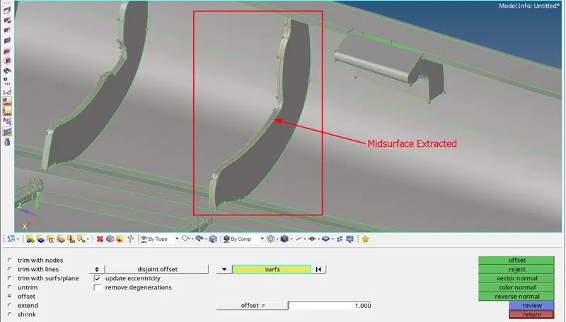
ii) By Extracting Midline -
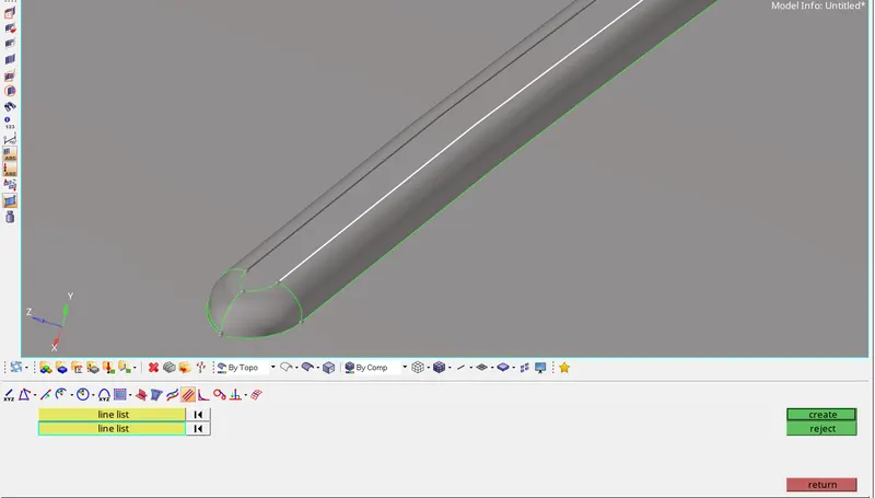
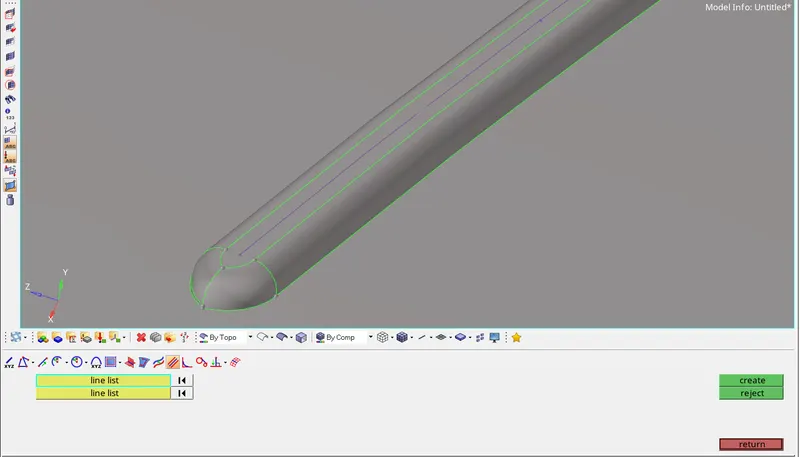
Geometry > Lines > Midlines > Line List 1,2 > Create.
We can use the Midline subpanel to create lines by interpolating between existing lines.
Two options are required to create a line using this method.
- Select a line list to use for the first side.
- Select a line list to use for the second side.
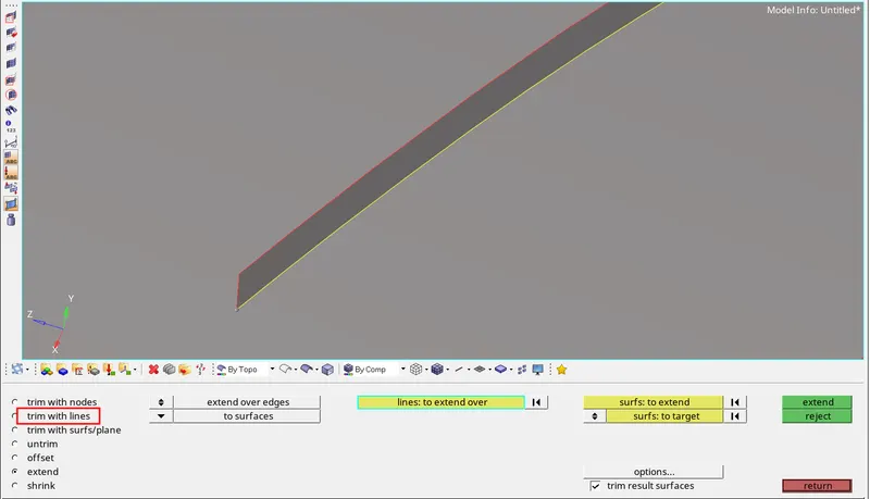
Now extract the midline for every region and to project those lines to the mid surface, use trim with lines tool to project on the mid surface. Make sure to set the mid surface component as a current component,Then only the lines will exist in that component. After that hide the parent component before projecting lines to the mid surface and project the lines to the mid surface.
After Projecting the lines, now the surface has been created using the ruled surface tool in the surface panel.
Geometry > Surfaces > Ruled Surface > Select Line1,Line2 > Create.
In the Line List, use the first selector to define the first edge of the surface to create. Use the second selector to define the second edge of the surface to create a midline using them.
- Extracting Mid Surface for the Other Surfaces -
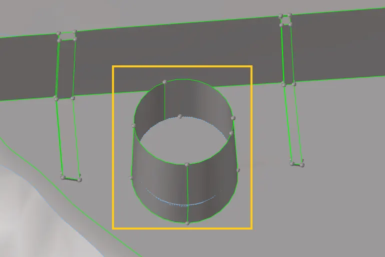
This cylindrical rib has no thickness. For this cylindrical rib, We are taking the mid surface randomly. We are splitting the surfaces and we are taking the mid surface using the ruled surface tool.
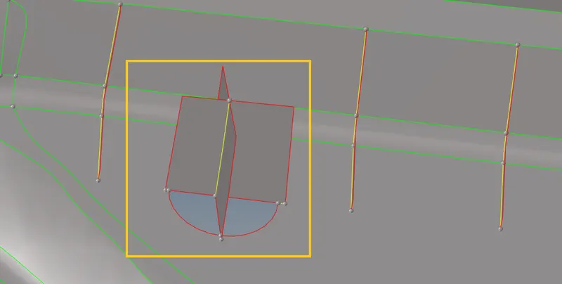
Now fill that hole using ruled surface. Mask those four surfaces and fill the hole using ruled surface.
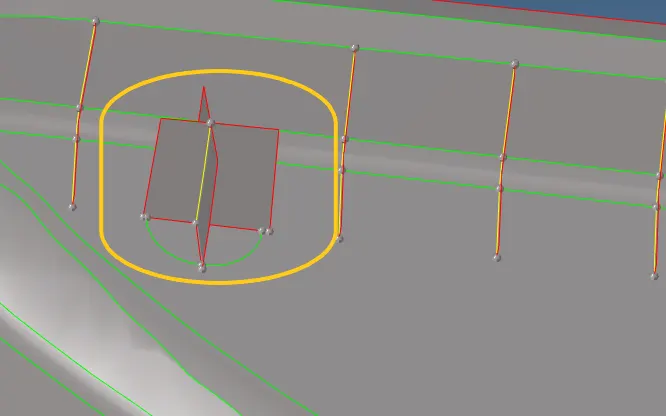
Similarly do that same thing for every doghouse like entities.
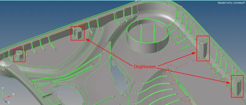
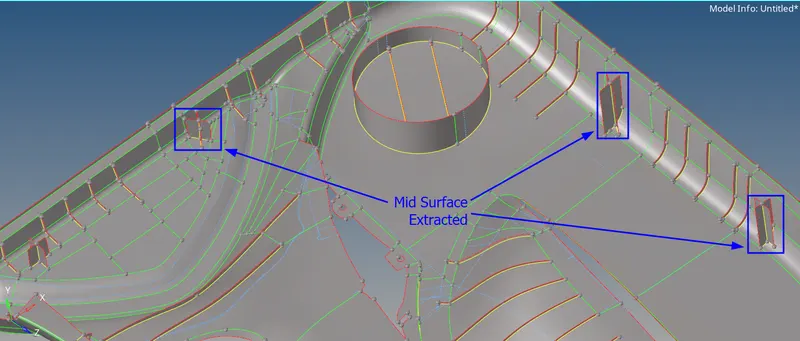
- Final Mid Surface Extraction -
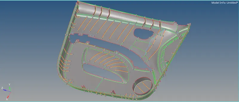
The midsurface that is extracted finally for the model can be seen in the image below.
6) Meshing -
After mid surface extraction, mid surface geometry cleanup is performed and once geometry cleanup is completed (e.g. surfaces are stitched together — no unwanted free surface edges inside the geometry), meshing is the next step.
- The mesh should look rather smooth and regular because of the fact that the analysis is based on your mesh and the mesh quality is key.
- Use the simplest element type suited for the problem.
- Start with a coarse mesh and understand the modeling results and then use a finer mesh if needed.
- Try to keep mesh related uncertainties to a minimum if possible. Keep it simple as it can get more complicated on its own.
Need of Meshing -
Finite Element Method reduces the degrees of freedom from infinite to finite with the help of discretization or meshing (nodes and elements). One of the purposes of meshing is to actually make the problem solvable using Finite Element. By meshing, you break up the domain into pieces, each piece representing an element.
Different Element Type Options for Shell Meshing -
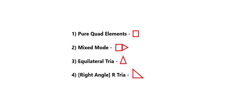
- Enter the quality criteria what they given for the component's -
Before generating a mesh on the surfaces. Enter the quality criteria given to us in the question.
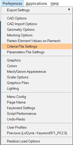
You can go and enter quality criteria in Tool bar > preferences > criteria file settings > checks for the element criteria > Enter values > apply > ok.
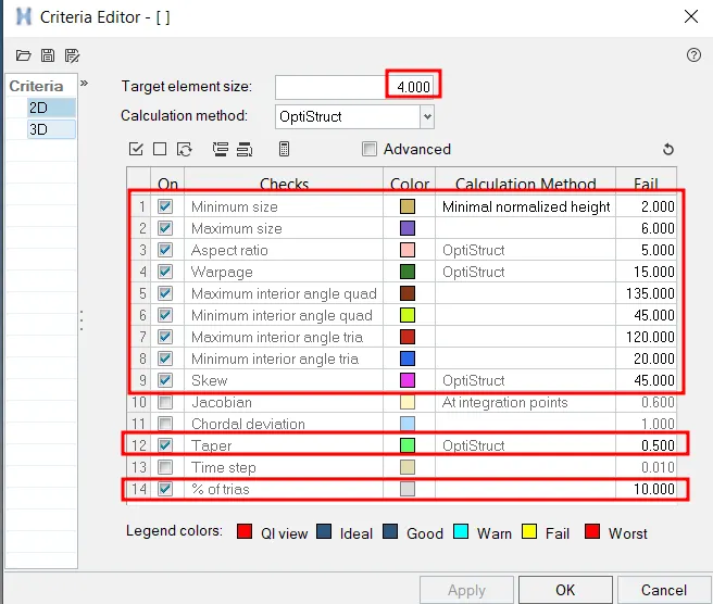
Save the criteria file settings for that component and save it to any other drives, cause whenever we open that component, we can open the element criteria file and criteria will be applied habitually instead of entering again.
Target Element Size - 4 Units
|
Sl. No. |
Quality Criteria |
Function / Definition |
Value |
|
1 |
Aspect Ratio Ratio |
Ratio of Max. Length by Min. Length |
5 |
|
2 |
Skewness |
Deviation from the ideal shape |
45 |
|
3 |
Warping |
Angle between the 2 planes of the same element(Quad) |
15 |
|
4 |
Taper |
Convergence of a Quad element |
0.5 |
|
5 |
Min. Length |
Shortest length of any given element |
2 |
|
6 |
Max. Length |
Longest length of any given element |
6 |
|
7 |
Min angle Quad |
Minimum angle in any given Quad element |
45 |
|
8 |
Max angle Quad |
Maximum angle in any given Quad element |
135 |
|
9 |
Min angle Tria |
Minimum angle in any given Tria element |
20 |
|
10 |
Max angle Tria |
Maximum angle in any given Tria element |
120 |
|
11 |
Tria % |
Percentage of Tria on any meshed surface |
10 |
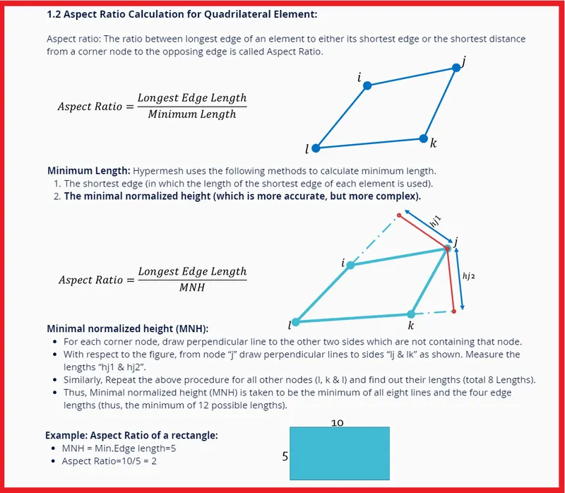
1) Aspect Ratio
- This is the ratio of the longest edge of an element to either its shortest edge or the shortest distance from a corner node to the
opposing edge ("height to closest node").
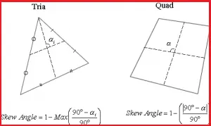
2) Skewness
- Skew of triangular elements is calculated by finding the minimum angle between the vector from each node to the opposing mid-side, and the vector between the two adjacent mid-sides at each node of the element.
- For Skewness: Ideal=0, But < 45 is acceptable.
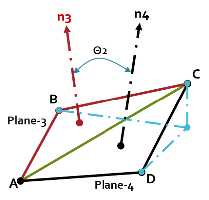
3) Warping
- This is the amount by which an element (or in the case of solid elements, an element face) deviates from being planar. Since three points define a plane, this check only applies to quads. The quad is divided into two trias along its diagonal, and the angle
between the trias’ normals is measured.
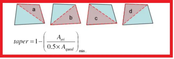
4) Taper
- Taper ratio for the quadrilateral element is defined by first finding the area of the triangle formed at each corner grid point.These areas are then compared to one half of the area of the quadrilateral.
5) Minimum and Maximum Length
The shortest distance from a corner node to its opposing edge (or face, in the case of tetra elements) is referred to as height to the closest node.
- Conditions to be followed while meshing -
Feature Capturing - Feature capturing is must while meshing.All the nodes must be connected to the shared edges.
Tria Management - Avoid higher numbers of trias.
Important Parameters in tria management -
- No trias in corners or edges.
- No opposite trias.
- No back to back trias.
- No trias in fillets or hemmings(We can have minimum but anyhow try to avoid).
- No rotational quads.
- No trias should share a boundary with the feature line.
- Connectivity between elements.
- Split and perform the mesh.
- Use mixed type mesh for irregular shaped surfaces and quads only for rectangular/square surfaces(Opposite sides should be parallel and equal).
- Start meshing from the center regions or from least free edges.You will get proper mesh density and proper mesh flow.
Now start meshing on the surfaces, Go to 2D > Automesh Panel > Surfaces > Element size = 4mm > Mesh Type : Quads or Mixed > Check for align and size > Mesh.

Select the appropriate mesh type based on the shape of the surface. Once we give mesh type for mesh, we can edit the mesh density by changing the number of nodes.
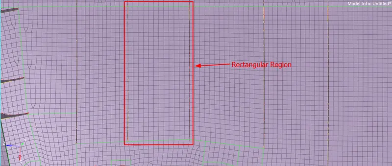
Here I have splitted the surface to a rectangular surface and meshed to get proper mesh flow. Make sure to check the Link Opposite Edges with AR. This option is to be checked when we are meshing on the rectangular surface.
Link Opposite Edges with AR - (Eg:If we have 29 nodes on the left side edge, It will project the same 29 nodes on the right side edge.)
Now if we mesh on the curved surfaces, choose the mesh type as mixed and mesh. If we choose quad mesh type here, the mesh elements will fail.
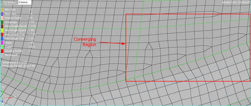
- Mesh Refinement -
Rebuild Mesh-
It is the process of remeshing existing meshes to generate a new mesh with good quality and flow.
The rebuild mesh functionality utilizes the same parameter and criteria files used by BatchMesher to define the quality criteria and relevant mesh parameters.
This algorithm saves significant time over the traditional automesh and quality correction approach.
Rebuild is currently supported for first-order 2D meshes that are not attached to 3D element faces.
The rebuild algorithm is useful for many different applications like
1) Remesh to adjust size, quality, and flow.
2) Change to a different element type.
3) Add or remove washer layers around holes, change the nodal density of a hole, adjust a hole diameter, or remove a hole.
4) Locally correct areas with bad mesh flow.
|
SI.NO |
Tool |
Purpose of the tools |
|
1 |
Place Node |
Move the node along the plane or curvature of the surface or away from surface. |
|
2 |
Swap Edge |
Each time if we click an edge, it switches to the next valid configuration. |
|
3 |
Element Optimize |
To move the midnodes attached to the element we are optimizing, enabled the with attached midnodes checkbox. |
|
4 |
Smooth |
It is used to improve the element quality of the surface. |
|
5 |
Split/Collapse Edge |
To use the split edge tool, left-click on an edge. HyperMesh splits the elements that share the selected edge in a way that will achieve the optimum quality. |
|
6 |
Drag Tria Element |
To use the drag tria element cleanup tool, left-click on a tria element and drag it to adesired location. HyperMesh highlights the selected tria element in pink.Drag both trias to combine when they are facing opposite direction. |
|
7 |
Split Quad Element |
To split a quad element, left-click on the quad element you wish to split. HyperMesh splits the quad element into two tria elements. |
|
8 |
Combine Tria Element |
To combine two tria elements, left-click on their shared edge. HyperMesh combines the two tria elements into one quad element. |
Now after meshing the entire component, check for
i) Connectivity (Free Edges)
ii) Duplicates
iii) Normals
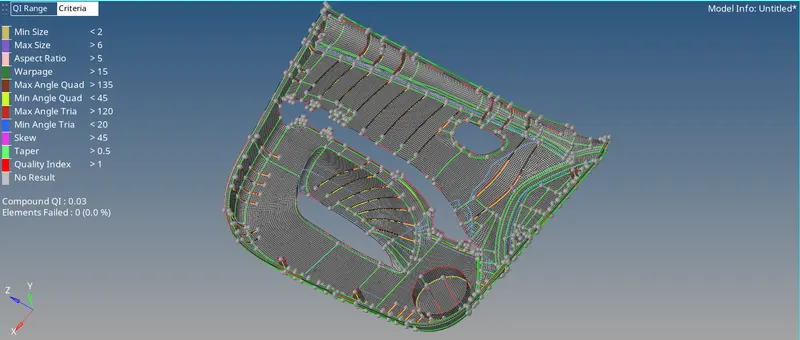
7) Assigning Thickness to the Elements -
1. Check thickness in geometry -
First check the thickness in every region and then assign a thickness by creating a collectors and organize it to that newly created collectors. Check thickness by distance tool or by dimensioning tool.
Geometry >> Distance >> Two Points >> Point1,2.
Geometry >> Dimensioning >> Point1 >> Point 2.
Create a Collector -
After measuring thickness, create a component and rename it. Organize the elements in ribs and cylindrical ribs to the newly created collectors.
Take a average thickness and assign it to the elements.
Similarly do the same thing for every rib region in the component.
3. How to Organize Elements -
We can use the collectors to organize entities such as elements, loads, and systems into their corresponding components, load collectors, system collectors, and so on.
Select an entity type to copy/move, then use the selector to select specific entities to copy/move. The current collector serves as the default destination.
Go to Tools > Organize > Elems (Select by Face/Geom) > Check Current Comp > Move.

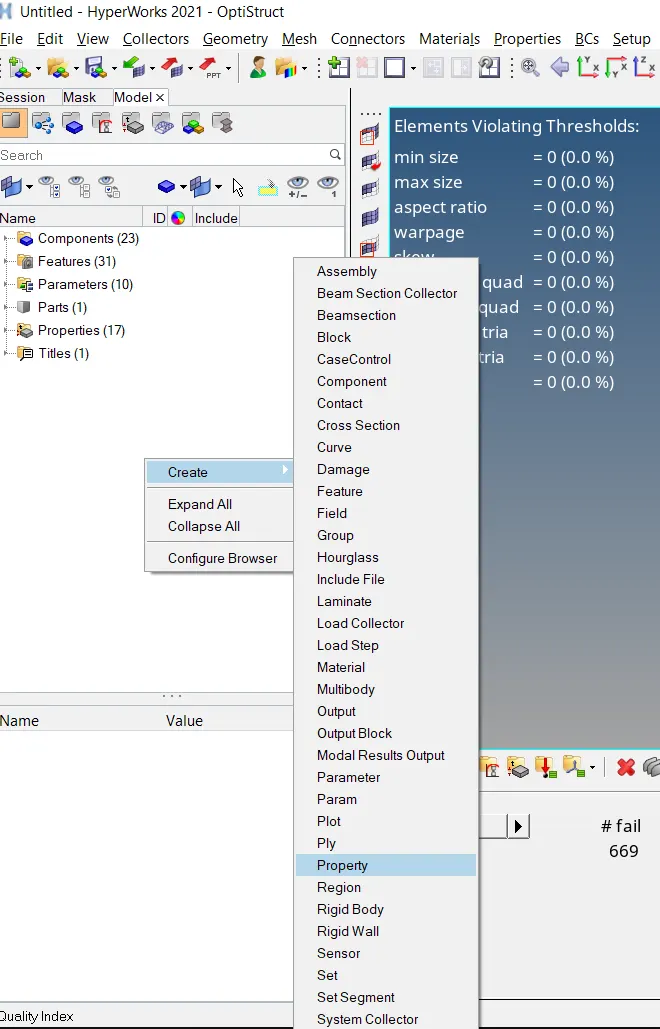
4. Assign Property to the Components -
First Create a property on the browser.
To create a property, Right click on browser > Create > Property.
After Creating a property rename it and start assigning thickness to the components.
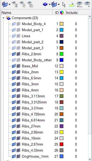
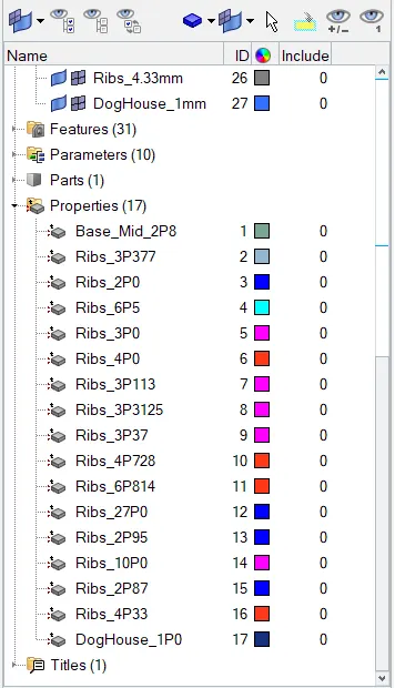
Now switch to the component view mode and check the model whether the elements are organized properly to the respective collectors which created newly.
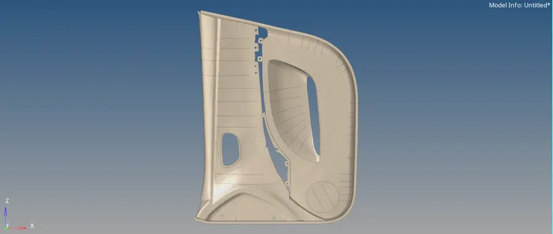
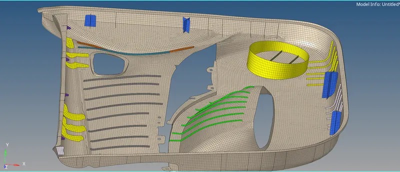
Now check the complete model,Whether every property has been assigned to the collectors.
To Check Go to Menu Bar > Tools > Component Table.
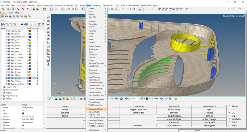
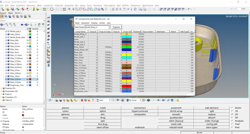
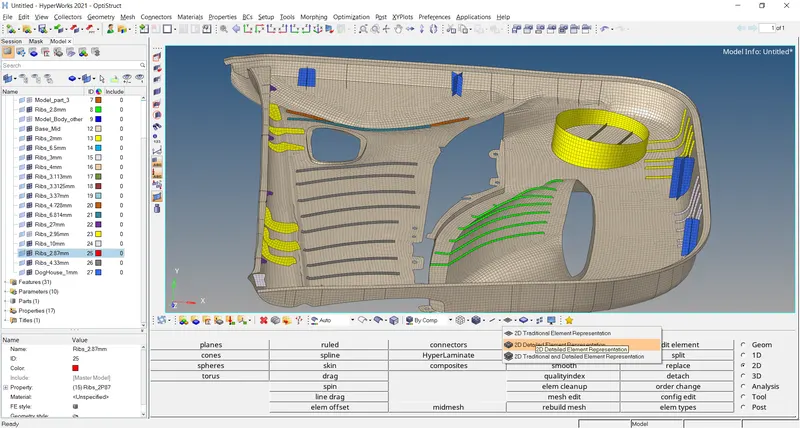
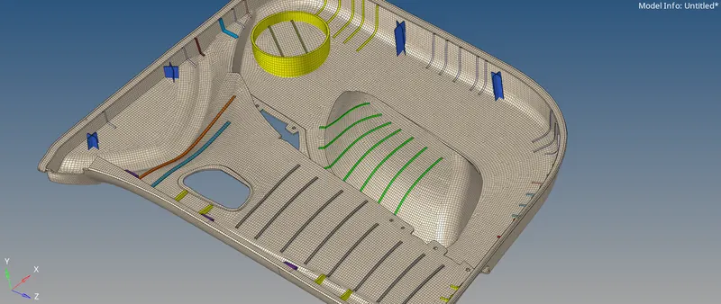
Now Switch to the 2D Detailed Element Representation,The thickness have been applied to the every region.
RESULT:-
- The mid surface has been extracted to the parent component.
- There are no surface deformations in the geometry.
- A well connectivity has been established between the surfaces.
- The features have been captured properly.
- A good mesh flow have been achieved with the zero elements failing for quality.
- Hence tria percentage with 1.6 % have been achieved.
LEARNING OUTCOMES AND CONCLUSIONS:
- To extract the mid surface manually for the complex plastic components.
- To clean complex geometry.
- To generate a proper mesh flow with low tria percentage.
- To assign thickness to the components.
.