Week 12:Project-1-Meshing of Door Inner Panel Challenge
OBJECTIVE :
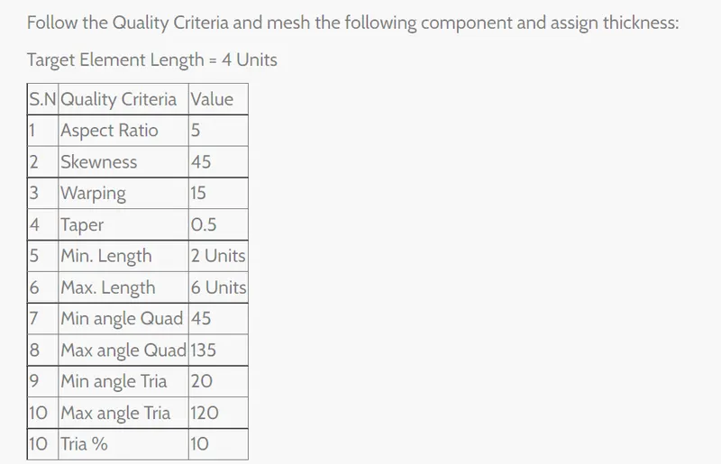
To follow the Quality Criteria and mesh the following component and assign thickness.
PROCEDURE :
- Import the given component and check the number of components available in the file.
- The imported component is fixed on the screen and the geometry color mode is changed from auto to by topo mode such that if solids are present it can easily identified and removed.
- Prior to working for the given geometry objective it is better to look for any errors like free edges, unfilled surfaces, unnecessary points etc. If any errors are found then it should be fixed using the options in the quick edit panel before extracting midsurface.

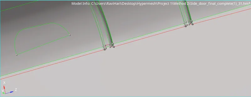
- Using the distance option measure the edges of the components that are displayed. Now the edges that doesn't fails for quality criteria are kept the same and the edges with fillets that may fail are defeatured using the surface fillets option.

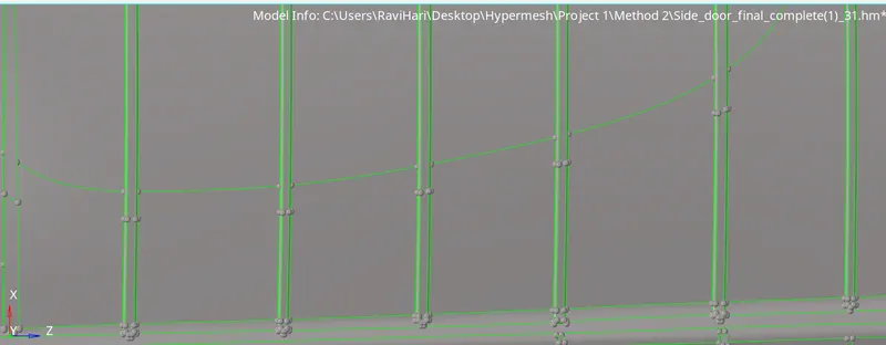
- On using the defeature option, the fillets are selected manually and the min & max radius value are given according to the quality criteria and the surfaces are defeatured. The defeature panel and the surfaces with the fillets/ribs are shown below.

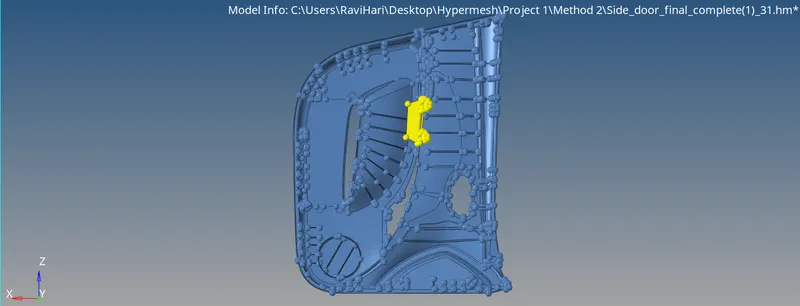
- As the given geometry is divided into 2 components they are moved to one component using the organize option in the tools section. Then on inspecting the given geometry has a part geometry with screw holes/rivets and has no attachment with the base geometry such that the unattached part is organized to a separate collector.
- Now while displaying the component by part in the geometry color mode, the colors assigned to each collectors of the geometry depicts the two components clearly in the geometry.
- Now the geometry cleanup is performed either in the parent geometry or in the midsurface after extraction. Usually the unnecessary edges are suppressed using the toggle edge option.
- As the given geometry is of various thickness blindly auto midsurfacing is not used here and hence the surfaces with less than 6mm thickness are midsurface extracted using the automidsurface with skin offset option and the remaining sweep surfaces, plastic and sheet metal components are midsurface extracted manually.
- For manual midsurfacing, the midsurface extraction of ribs are made by using the midline option and the midline created in then duplicated and projected on the midsurface. The alternate method preferred for ribs midsurface extraction is offset surface in the surface edit panel by which the surface is duplicated and offsetted to the midpoint.


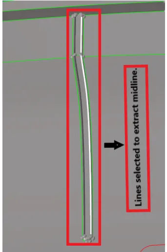
The midlines created are then surface filled using the ruled surface option and thus the midsurfacing of the ribs are done.

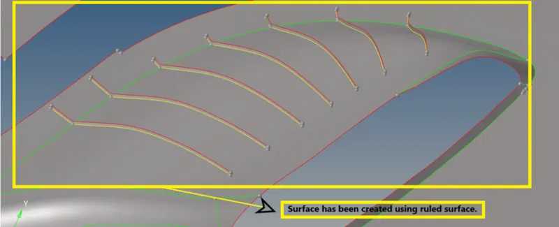
- Now the midsurface extracted are present with gaps/unfilled surface at some regions and in those regions the surfaces are either extended and trimmed using the extend surface option or the edges are unsuppressed for filling the surface.

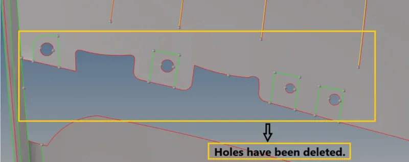
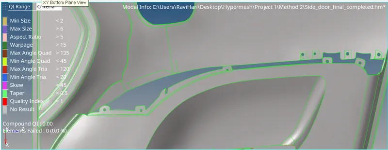
- In the parent geometry there are number of holes with free edges (i.e)., the screw holes and those holes are projected on the midsurface using the trim with lines in the surface edit option. Then the trimmed surface on the midsurface is deleted such that the hole is created with a free edge.

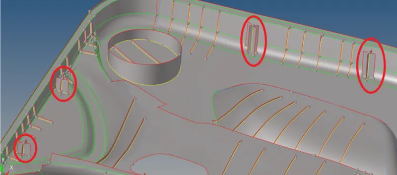
- For the midsurface extraction of the doghouse and the cylindrical rib in the parent component is done by creating the locators that shall represent it and the locators are formed by creating midlines on all four sides of the doghouse or cylindrical rib and ruling the surfaces between the two opposite midlines.
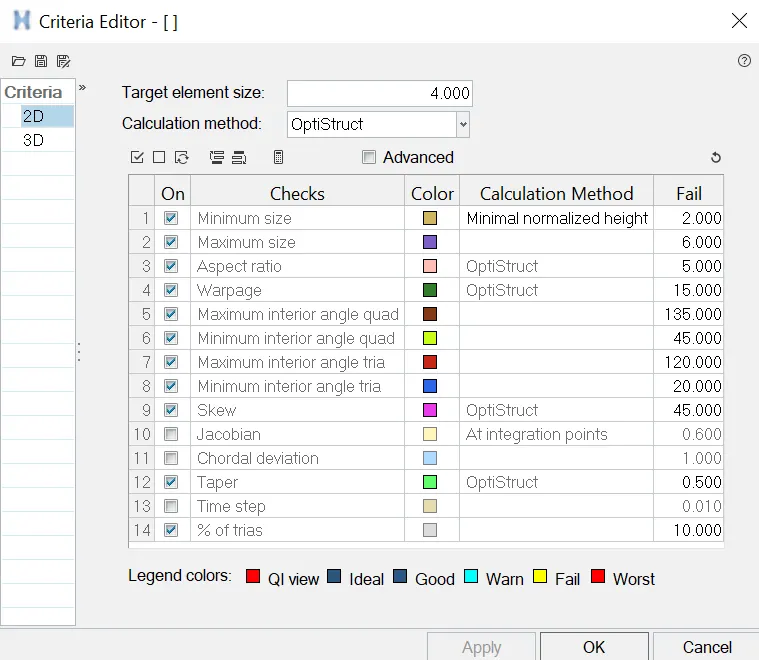
- After the midsurface extraction is properly done the meshing of the surfaces is progressed. The meshing is done by following the quality criteria given and the criteria is fed into thegeometry using the criteria file settings option in the preferences tab.
- The meshing is done by using the automesh option and the mesh is started from the region where there are less free edges or region with lesser surface area such that the mesh flow goes continuous till the complete surface is meshed.
- The meshing criteria should be followed properly using the mixed type of surface meshing and the tria concentration should be reduced as much as possible to improve the mesh flow of the component.
- The mesh near the holes should be properly aligned by created a node at the arc center and rotating the mesh to make it proper and continuous. The mesh that fails are remeshed using the automesh option and the element cleanup is done using the quality index panel.

- After meshing the mesh is checked for connectivity, duplicates and free edges. The free edges are inspected using the edges option and if any free edges are available in between the mesh it can be fixed by equivalencing or by replacing the nodes of the elements at the free edges.
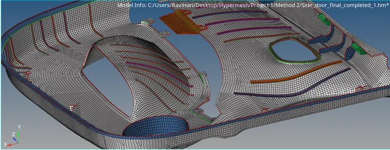
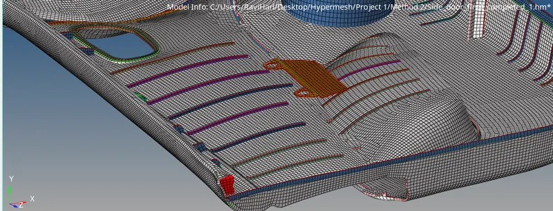
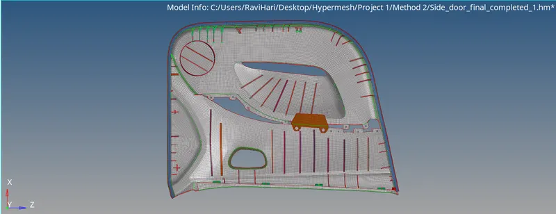
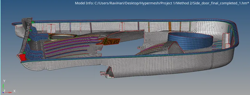
- The final meshed model is as shown below
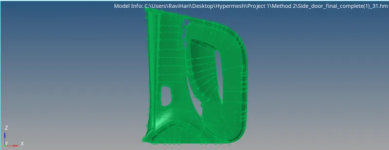
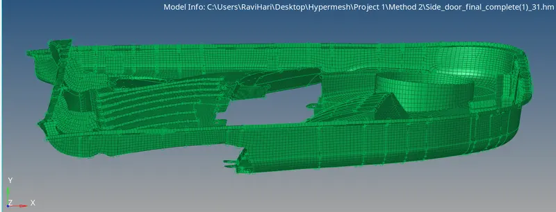
- Soon after meshing the thickness of each region/part is measured using the dimensioning tool/distance option and the regions/parts varying in thickness value are kept in different collectors. The property is created and assigned for each and every collector based on the thickness value and color difference is also provided for the purpose of 2D Detailed Element Representation.
- The 2D Detailed Element Representation of the components is as shown below
RESULT :
Thus the given model is meshed by following the quality criteria and finally assigned thickness to the entire component successfully.