Meshing the Plastic Component of a Car Side Door Model using Hypermesh
OBJECTIVE : To mesh the plastic component of a car side door model with respect to the given quality criteria using hypermesh and assign thickness property to each and every part of the model.
MODEL GIVEN :
CAR SIDE DOOR PANEL -
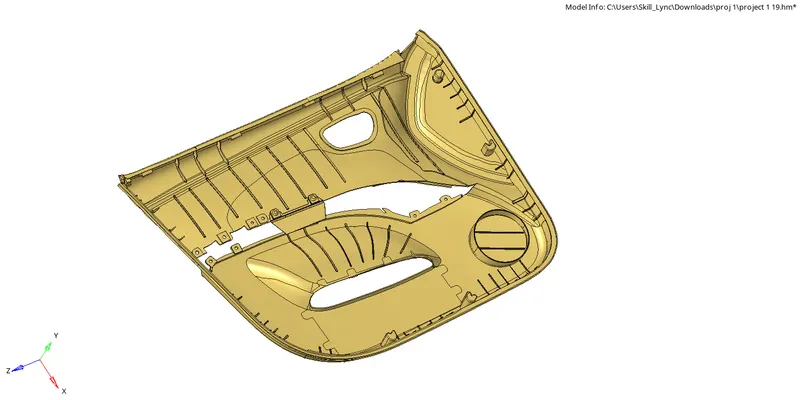
The door panel covers internal parts like the window regulator, the power window motor, and the wiring. In older cars, door panels used to be made out of cardboard and upholstered with material that matches the rest of the upholstery within the cabin. On the other hand, most modern cars have door panels made from plastic.it serves as an interface between the interior of the car and the inner workings of the door, and between vehicle occupants and the door. They are expected to meet a variety of design specifications regarding safety, aesthetics, and functionality. In addition, they are expected to continue the material theme of the dashboard and pillars while concealing intricate electrical and mechanical components for operating locks, windows, and other features. The door panel has evolved from a simple two-part system of latch and simple winding mechanism to a more sophisticated enclosure. Doors currently have an inner full-width panel consisting of armrests, switches or other controls for windows and the locking mechanism, convenience lights, audio speakers, storage compartments, and other features.
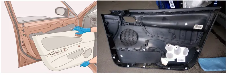
fig: interior car door panel
PROCEDURE :
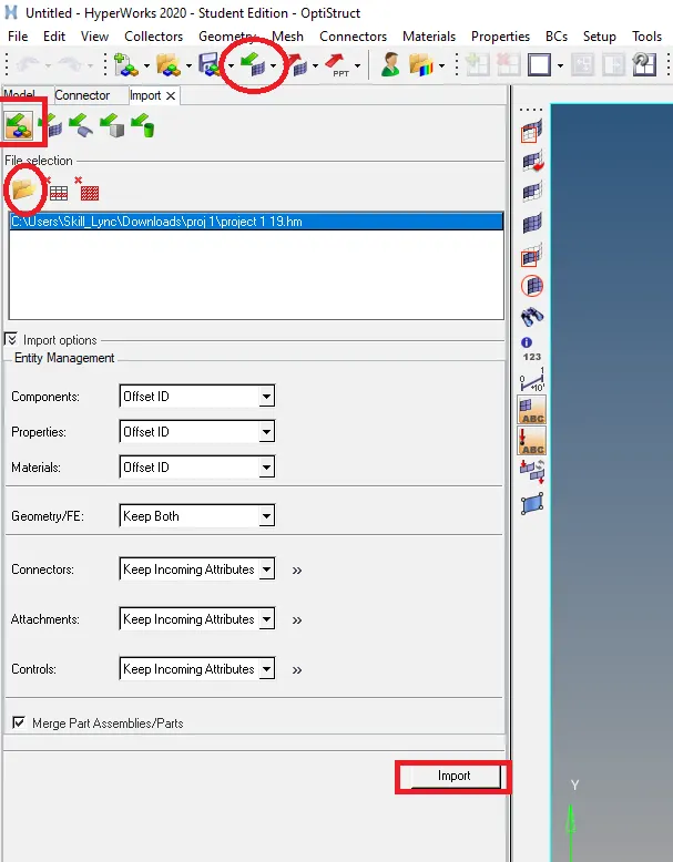
let's import the given model in hypermesh using import option available under tile bar or else we can just directly import it by choosing open model icon.
After importing the model in hypermesh the first step we takeup is examining the model for any deformations and missing surfaces. We change the view from "by auto" to "by topo" to see how the connections and geometrical lines like free,shade edges and non-manifold lines later we clearup all those errors which in term we call it as "Geometry or topology cleanup".below image shows the topology view of imported side door model from this we can observe that there are some free edges appearing,to clearly get a view of all the free edges and missing surfaces we switched to wireframe mode.
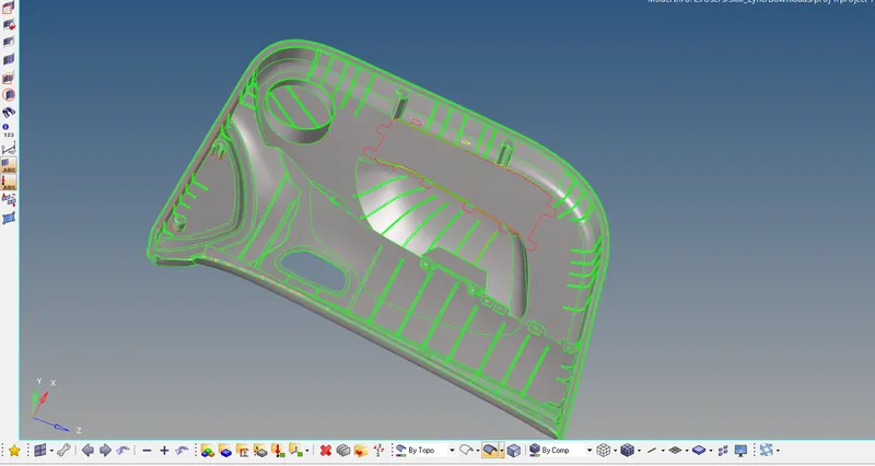
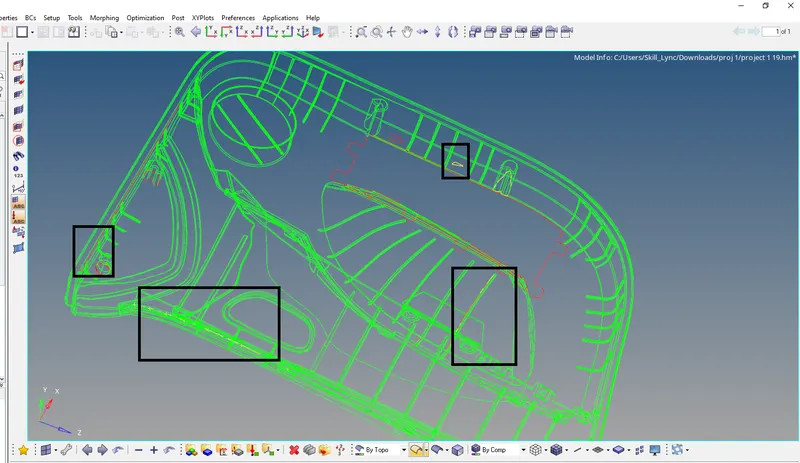
we can see that there are some missing surfaces,free edges and deformed surfaces.mostly we are going to fix those issues one by one using tools/options given under the geometry menu which have almost every option to fix the topology issues.
- TOPOLOGY CLEANUP
Topology is how you connect to different surfaces in the geometry which includes
a.free edges which are red in colour say that thay are not connected to anything else
b.shared edge which are green in colour are connected by two surfaces
c.non-manifold/T-junction edge which are yellow in colour resembles that they are connected by three or more than three surfaces.
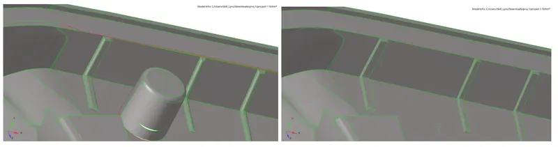
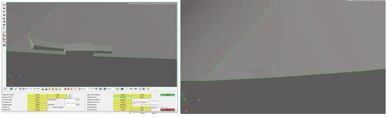
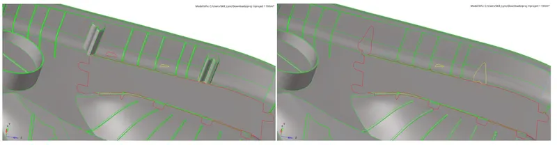
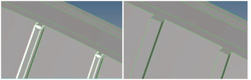
the whole point of Geometry cleanup is correcting the connectivity errors between adjacent surfaces which possibly include free edges or unconnected adjacent surfaces,duplicate surfaces,missing surfaces etc and for having good meshflow and minimum quality errors in the mesh it is better to toggle some lines and make some new cuts on the surface geometry keeping in mind about the minimum and maximum size of the element we are going to mesh.in the below images we can see at some feature areas we toggled and made some new cuts without affecting the geometry.the tools we use here are mostly in quickedit panel.go to geometry-quickedit-toggle edge to remove the lines which we need most probably we will be removing the lines which are at a distance lower than minimum element length later that we use quickedit-splitsurfnode or splitsurf/line tool to make some new cuts.There are some features with shape of cylinder and dog house which are hollow without any internal surface to take mdsurface so we prefer to delete those features and fill the holes where it is deleted using filler surface option under quick edit panel.
we use the Surf Fillets subpanel to identify and remove surface fillets (curved surfaces that create a smooth transition between relatively perpendicular geometric entities).we can identify fillets based on radius, because fillets are always uniform arcs. You can also select a fillet by picking one of the edges that it connects. Once found, fillets can be removed using tools that display automatically after the find process.When removing surface fillets, the algorithm starts after you select the surfaces and click remove. Selected surfaces are considered to be fillet surfaces. The work of the removal algorithm does not depend on the result of the work by the fillet detection algorithm (which is invoked by clicking find fillets). You can manually select all of the surfaces that you believe to be fillets and want removed. Once such a decision has been made and the surfaces are selected, the removal algorithm does not interfere with this decision in any way other than simply failing to defillet wrongfully (in its opinion) selected surfaces.
All surfaces adjacent to the fillet (selected) surfaces, and connected to them by green edges, are extended and intersected with each other. Surface extensions are trimmed by intersections with other surfaces. If trimmed extended surfaces and original fillet surfaces can form a closed body
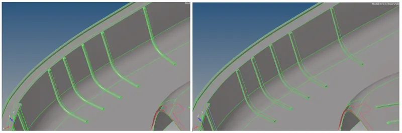
since there are so many ribs with fillets are present in the model we will defeature all of them at once for that we need to specify minimum and maximum radius.here we gave 0.7 and 2.7 considering the minimum element size.we will use the Defeature panel to find and delete fillets on surfaces and surface edges, and duplicate surfaces.Each of the subpanels allows us to manually select the feature that we wish to delete, but also supports a three-step process that can locate such features for us.

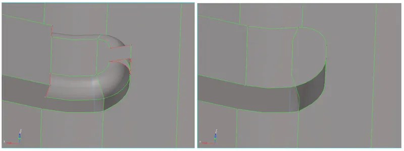
in some ribs defeature might not work properly so we need to fix them manually using extend and toggle tools .here in the below image we can see the repaired surface of fillet.
- EXTRACTION OF MIDSURFACE
Midsurface meshing is opted for components where the geometry thickness is small when compared with the span length of the components, so if you see most of the automotive structures are of sheet metal and plastics, where the length of the component is large when compared to the thickness, hence for this reason we opt for mid surface extraction.since the side door panel have small geometrical thickness we deploy mesh on midsurface of this model]
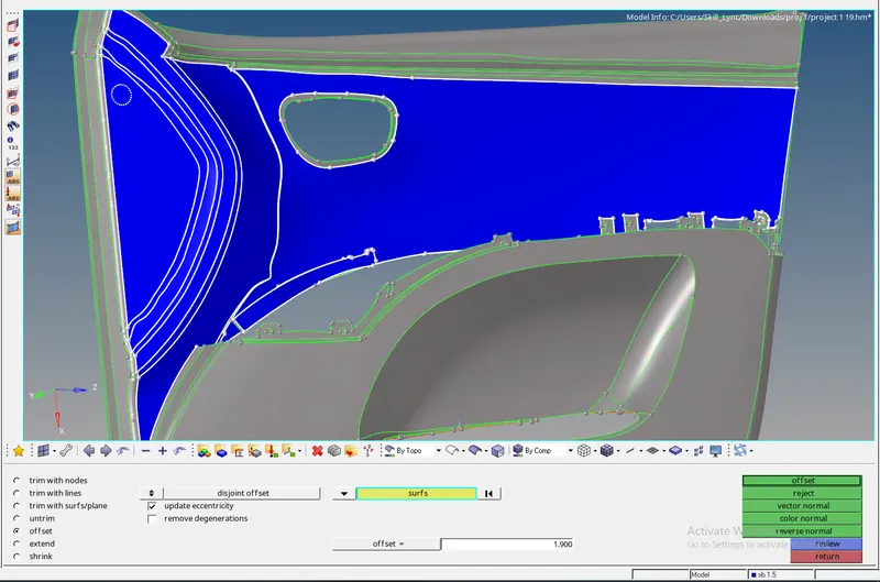
in this model the automid tool didnt work perfectly so we make mid surface using offset option available in surface edit panel.we first select the surfaces we need then we measure the thickness lets say if the thickness of the component is 2.8 we duplicate the surfaces we selected before to the component we need and then we click on the colour normal to check the offset direction. if the surface shows in red mean it will offset outwards while other colour blue indicates that the surface will offset inwards. so we reverse normal " the direction based on the colour we get on the surfaces and offset the surface to half the distance i.e., 1.9.
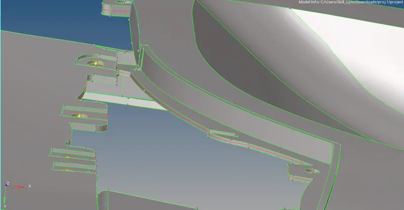
after extraction of main surfaces we make middle surface for the ribs and speaker holders components.if we can observe in the model some of the ribs are having variation in the shape and thickness.
for ribs with uniform thickness we can make midsurface easily and exactly in the middle with the use of fine edit tools in midsurface panel then we have to select surfaces both sides to crate a middle surface.
for uneven ribs we first try to make a middle line on the surface using lines list under ruled option which is available in surface panel. after creating the line we trim the line to the base surface using trim with lines option in surface edit panel .later we make middle surface by selecting both trimmed lines with ruled option.the below image shows the midsurface taken for non-uniform rib.
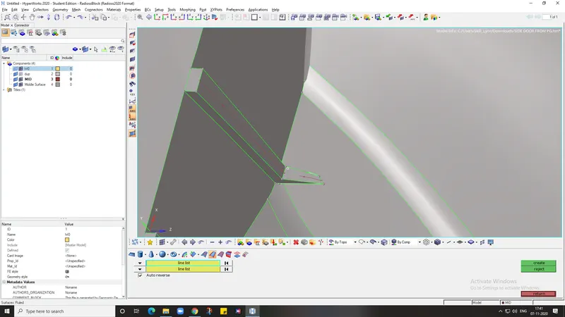
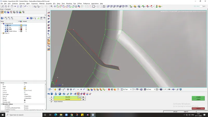
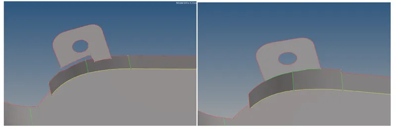
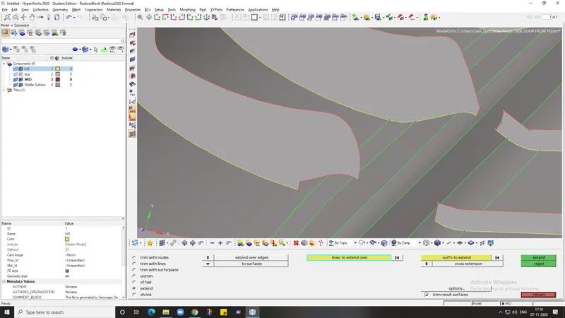
here in this region we will offset the bottom surface which is preferable to make midsurface for this type of geometry.after taking the mid we have it with boundary surfaces as same as in parent geometry.since the surfaces are somewhar far to each other we have to extend both the surfaces by some distance until they intersect each other.we go to surface edit-extend,the we select extend over edges with some distance.we will choose some random value and extend the surface until it meets.after that we can delete the extra extended surface using time with surface panel.
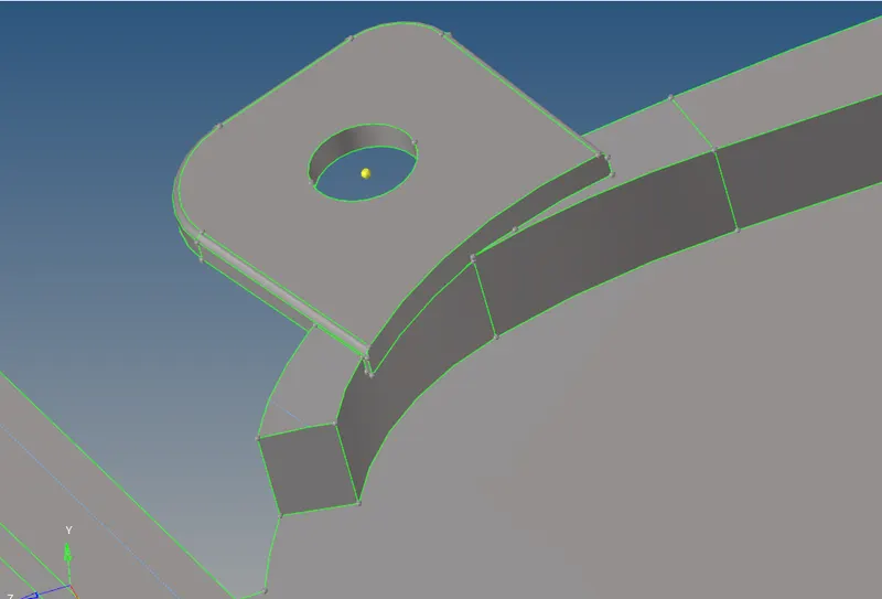

the below image shows the midsurfaces which are attached properly.
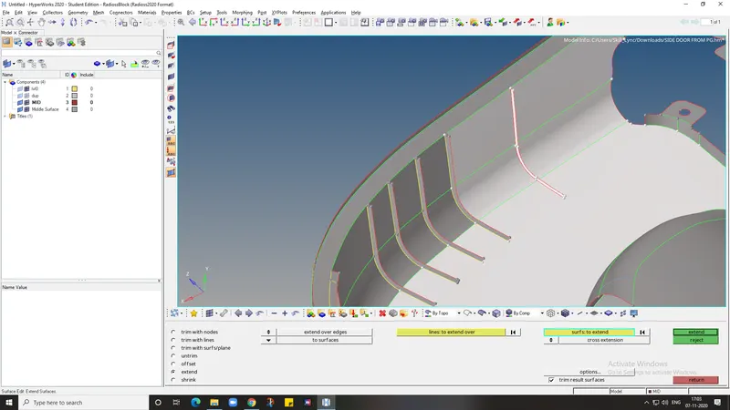
all the other rib areas are also have to extend to the base surface.so we select all the edges of ribs at once and select the base surface where ribs are present and then procced with surface to extend option in surface edit panel.
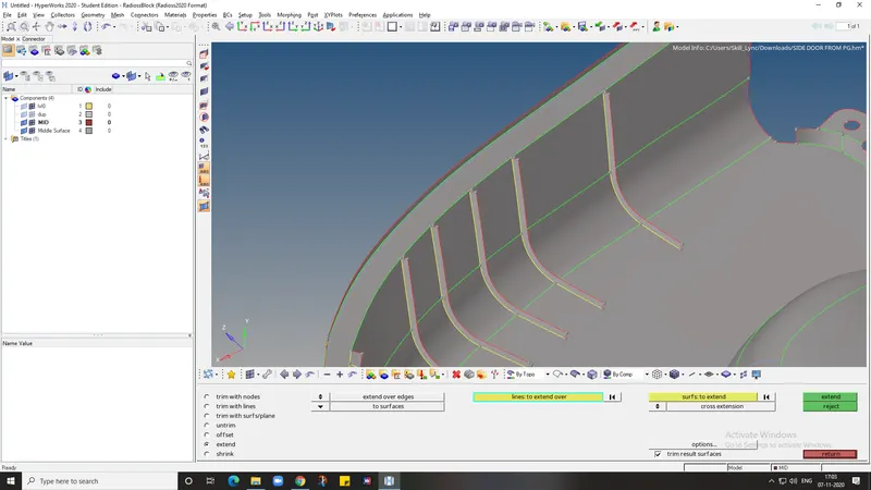
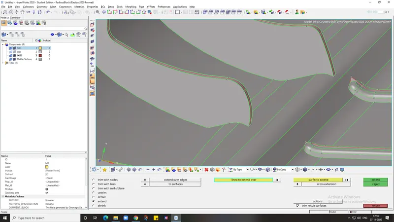
there are some other ribs which looks like they are attached to the base but actually they are not. We have to be careful while extending them by examining the parent body.
 0
0
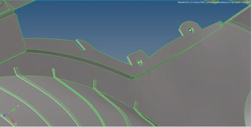
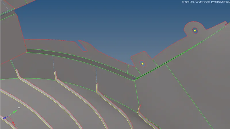
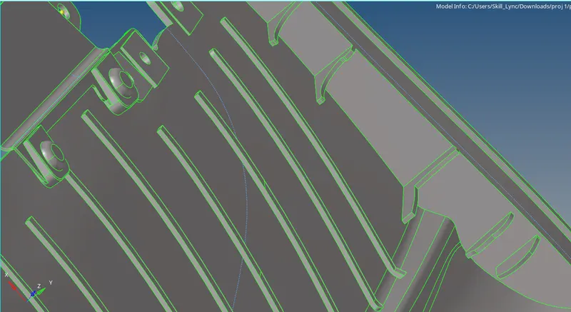
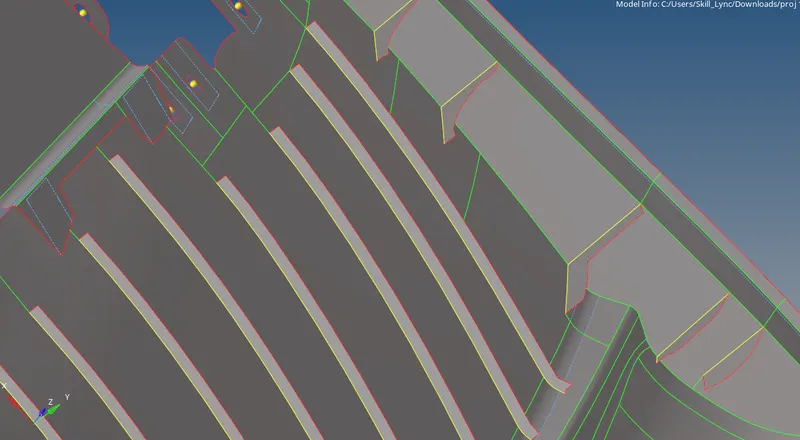
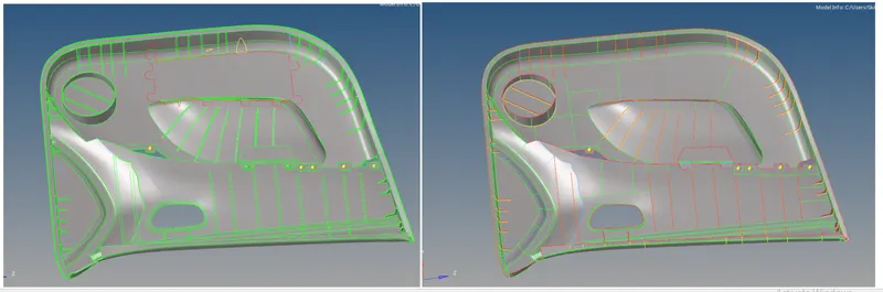
after taking mid of all ribs and features we check for all the connectivities by comparing with parent body,and also we will delete those extra extended surfaces which are not preferred in midsurface.the below images shows various areas where we took mid properly without any mistakes.
- MESHING
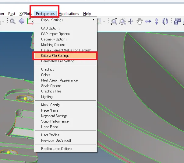
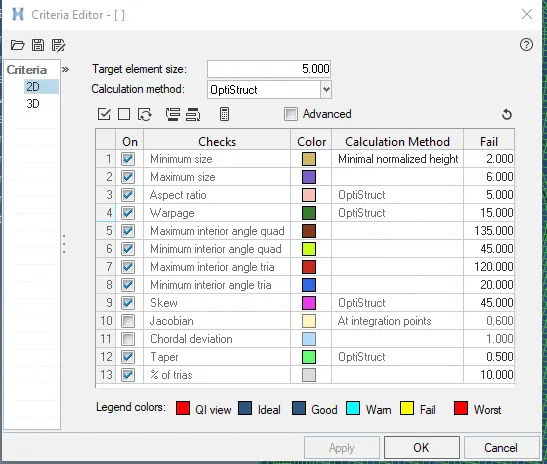
Now we move on to the important step which is meshing.to mesh a surface we have to specify element size, element type and some quality criteria values which is already given to us in the challenge.to enter the criteria values we will select preferences-criteria file settings and enter all the values.
we first mesh the feature areas which are little complex and then proceed with flat areas since we can manage the trias and mesh flow easily on flat surfaces and free edges.there are some of thumb rules which we must follow while meshing to get good result,they are
- features should be captured
- no back to back trias
- there should be connectivity between elements
- no opposite trias
- no trias in fillets or hemmings (can be compromised a little bit at some converging fillet corners)
- no rotational quads
- no trias in corners or edges
while meshing we turn on align and size in mesh options to get proper mesh according to the size and shape of the surface with low quality errors.
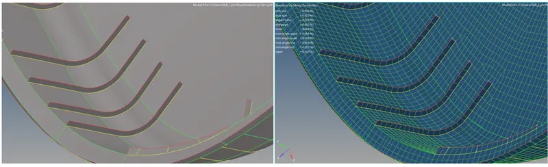
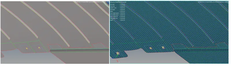
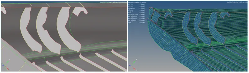
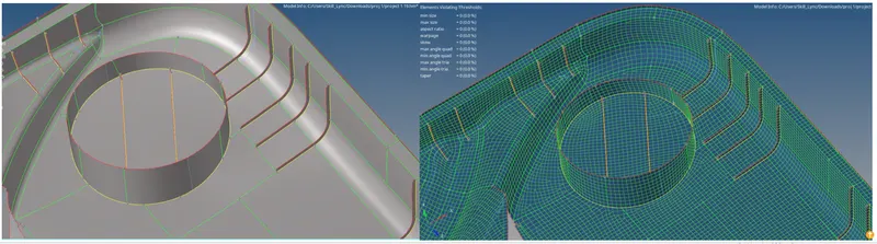
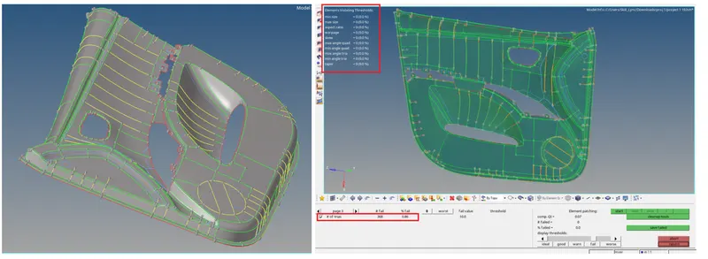
these are some of the images of the model where we meshed with zero quality errors.
- ASSIGNING THICKNESS
after meshing all the surfaces we will assign thickness to each and every surface component by measuring its thickness in the parent body.first we will make properties one by one by specifying thier respective thickness values we measured.
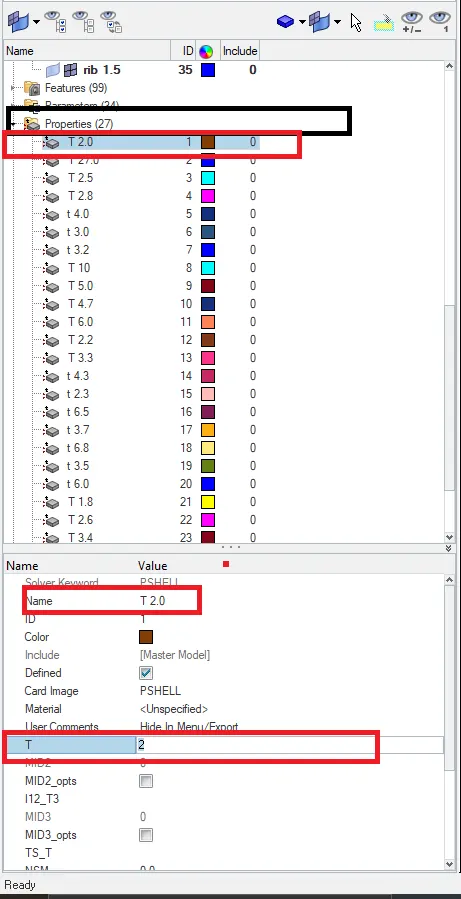
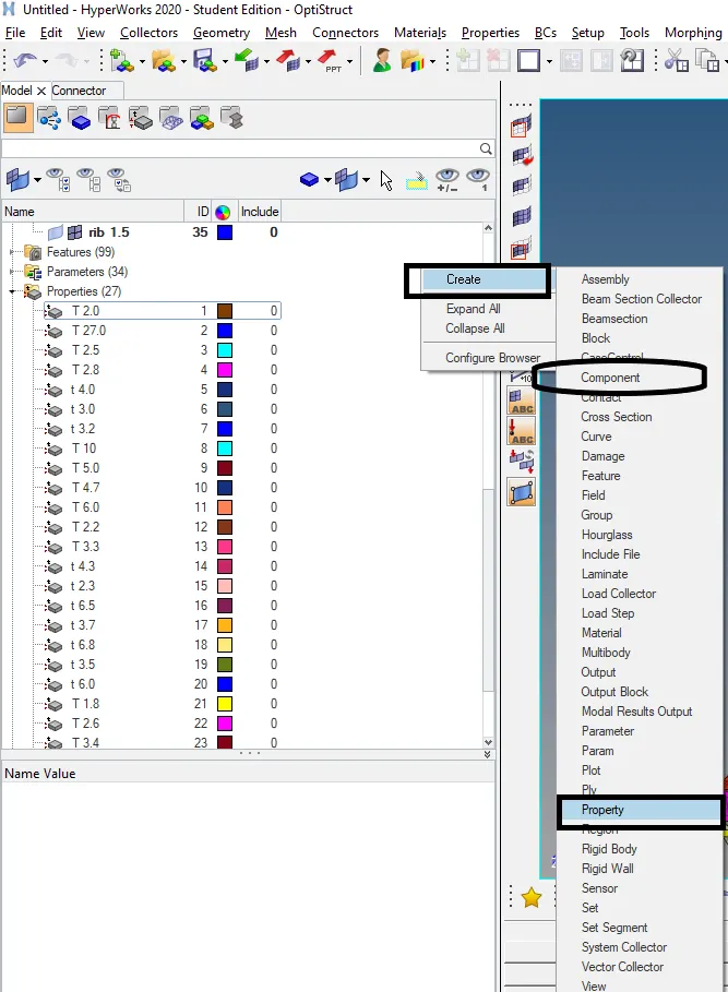
here we created total of 27 properties specified with different thickness values and colours.these colour variation helps us in identifying the component with rest to its thickness after assigning to the components.now we continue creating 27 components with names of thier thickness values to avoid confusion while assigning.we right click on the "model view" tab which will open a popup menu that will help us to create-component. after creating all the components we will organise all the shell elements on the surface geometry in thier respective components according to thier thickness values.
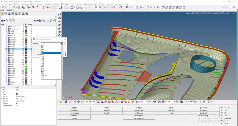
to organize we will go to tools-oraganize-select elemets and select the component we wish to transfer.after that we will assign all the properties we created before to these components.by the time we assign the thickness property to the compoinents they will change the colour.if we cant see the change then we should have to turn on "by prop" view.in the below image we can see that a property with thickness value of 3.3 is assigned to a rib component.
To see the thickness we assigned we have to turn on "2d detailed element representation" option which is available under workspace.
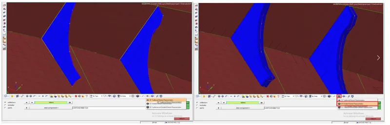
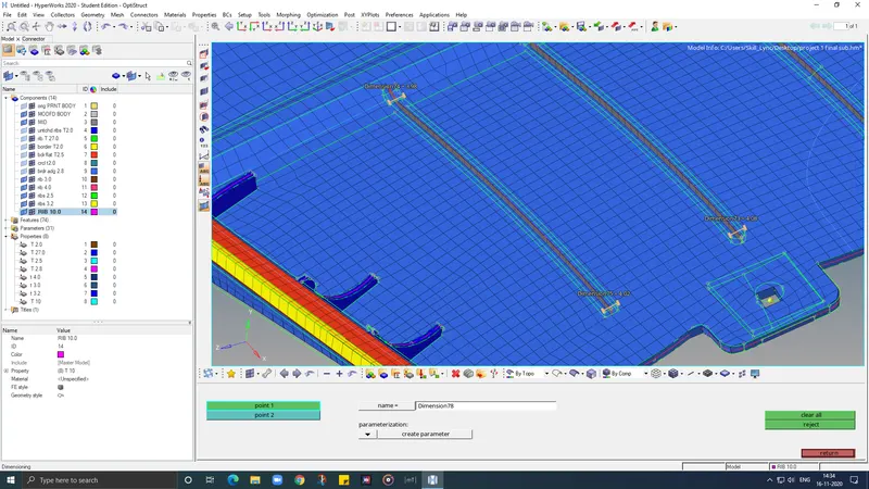
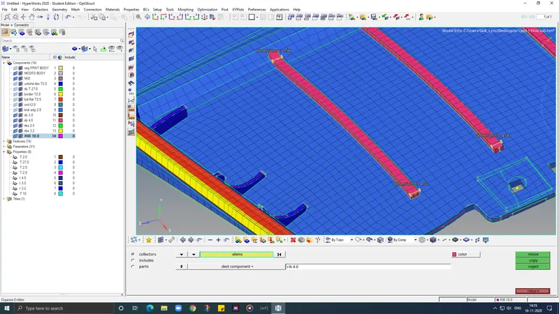
Finally thickness is assigned to all the components and 2d representation is shown below in comparison with parent body.
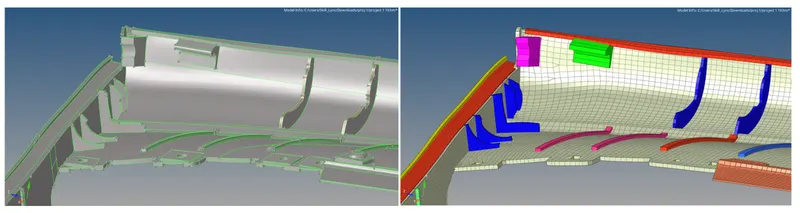
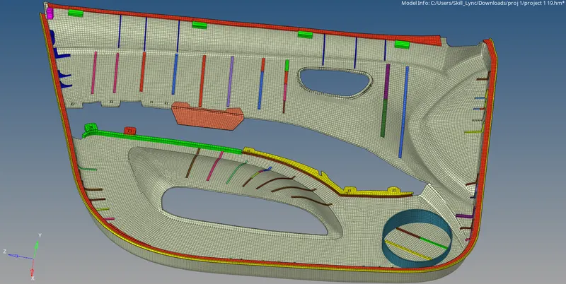
RESULT:
1.Midsurface is extracted susscessfully from the given side door component
2.Deployed 2D mesh with good mesh flow which is having zero quality failures and low tria percentage.
3.Assigned thickness property to all the components.