Week 12- Final project
The door trim panels are key components in making up the interior space of a vehicle. The main materials used include kenaf, which grows year round and has excellent CO2 absorbing properties, and plant-derived plastic, making them environmentally friendly as well..
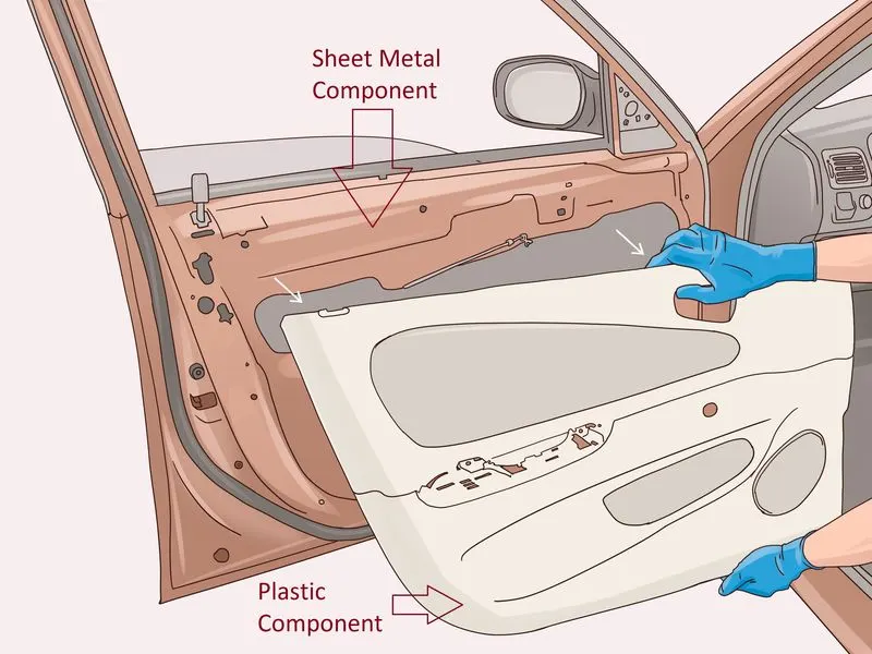
The following is the steps followed for the designing of the plastic model:
- Class A surface and the master section is received as an input.
- Draft analysis of the class A surface with a dummy tooling axis.
- Find out and mention the surfaces that clearing and not clearing surfaces with the minimum draft angle required for non clearing surfaces.
- Creation of a class B surface by offsetting the class A surface or by extracting each surface and matching the class A surface with the distance of 2.5mm( i.e the thickness of the plastic model) as given in master section. Make sure to extrapolate or have an extra length of the class B surface so that it can be easliy trimmed with the class C surface.
- Creation of the class C surface from the class A surface boundary, draft angle(max 3) should be provided to all the class C surface that are parallel to the tooling axis. No need to provide the draft for the class C surfaces that are perpendicular to the tooling axis. Make sure to extrapolate or have an extra lenght of the class C surface towards the class B surface for easy trimming.
- Join the class C and Class A surface and then trim it with the Class B surface.
- Make sure the surface model formed is a closed surface.
- Extract the part model from the surface model.
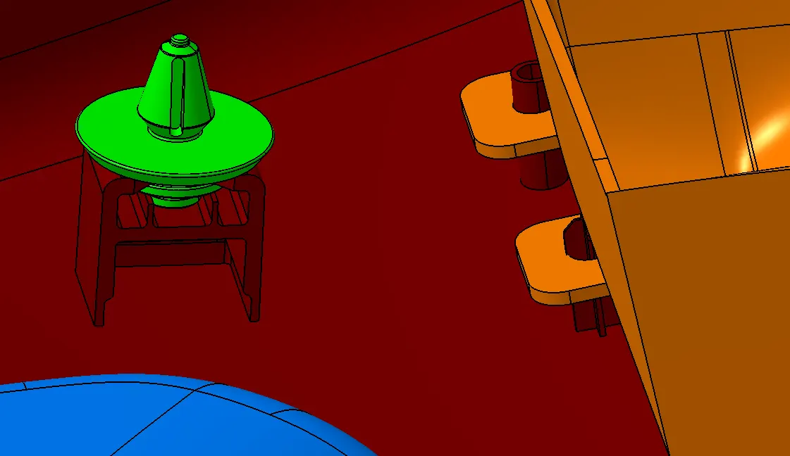
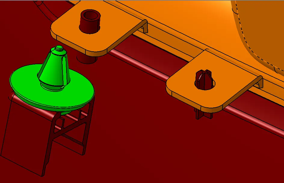
- Design the fixation features(Locators, Heat stakes and Dog House with the fixation for the Push pin) wherever required as per the design rules.
- Assemble all the Parts models.
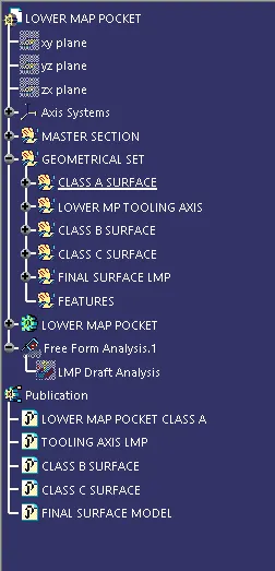
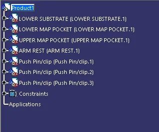
Below are the design tree structure of all the plastic components designed using the Class A surface and the master section provided.
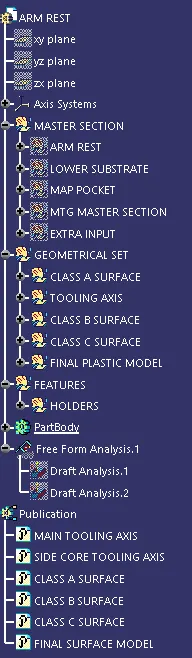
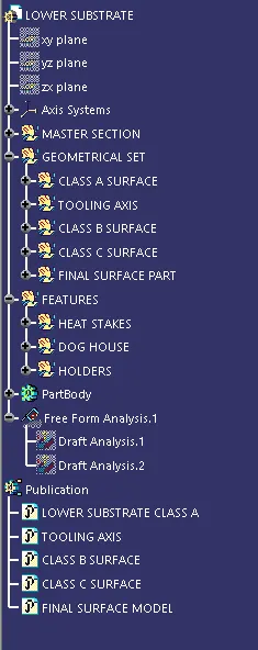
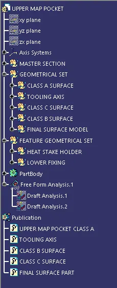
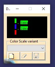
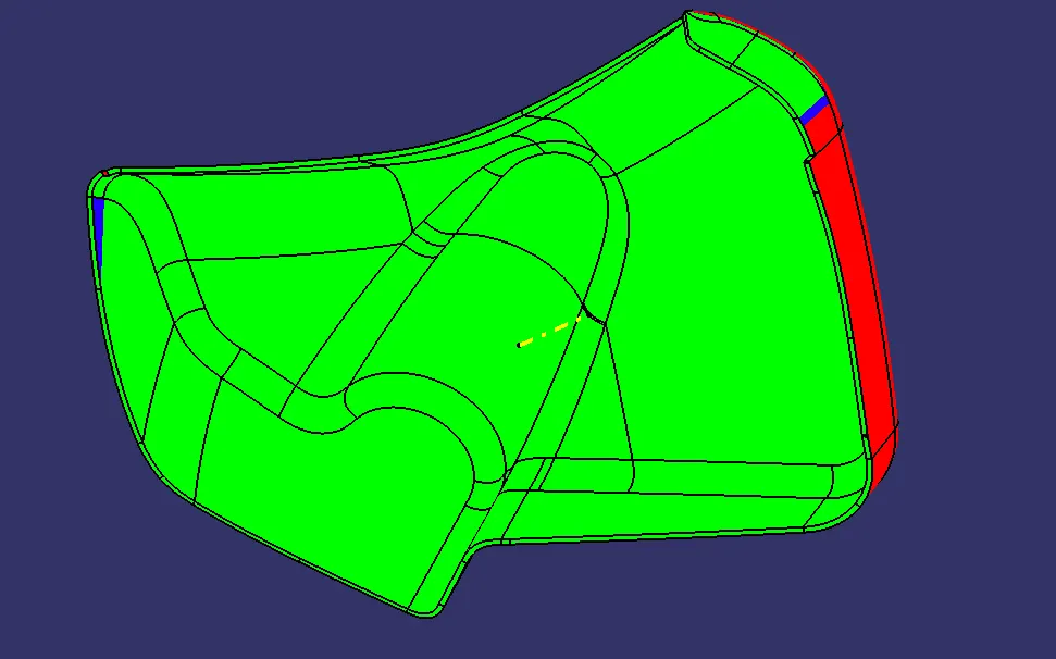
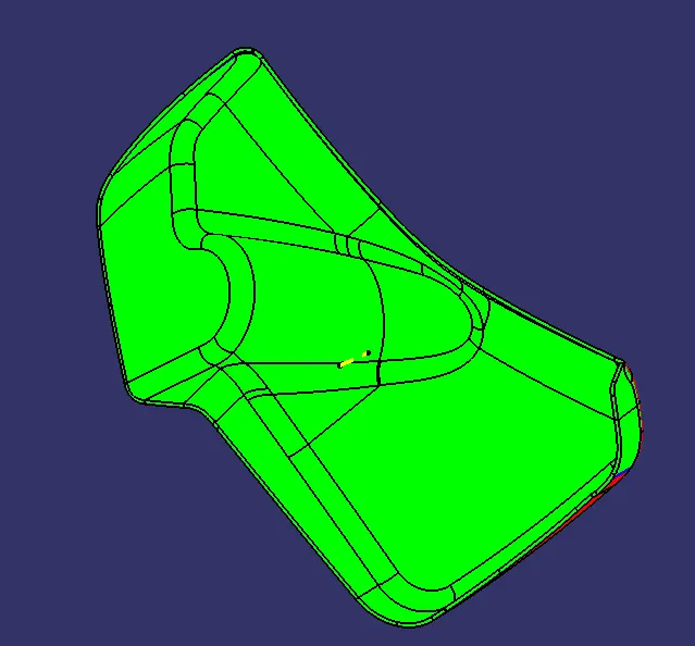
The colour coding used for the draft analysis of all the parts.
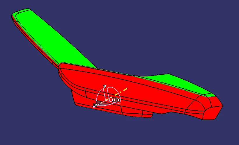
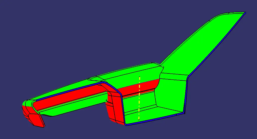
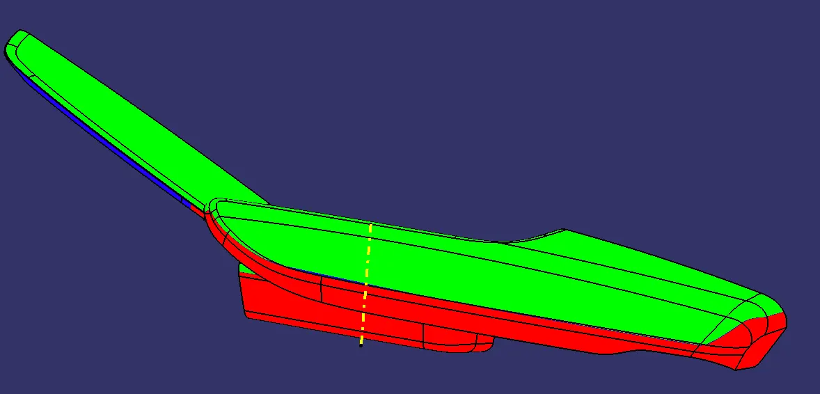
Draft analysis of Armrest class A surface: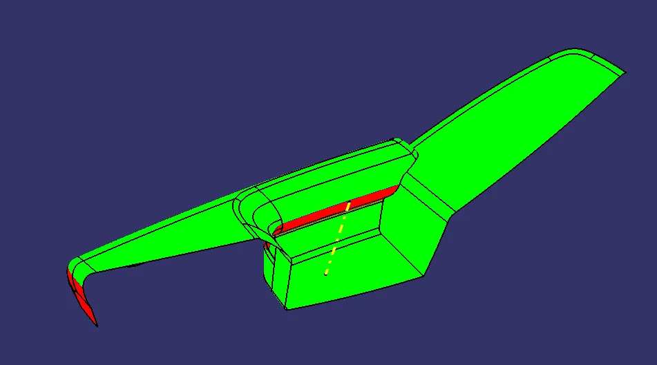
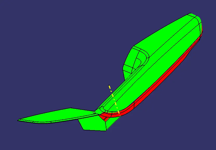
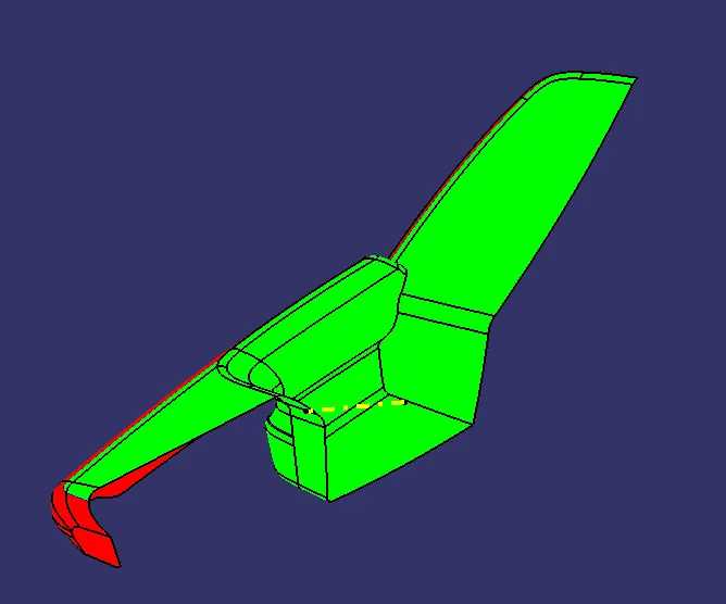
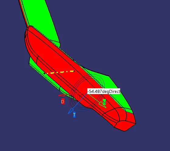
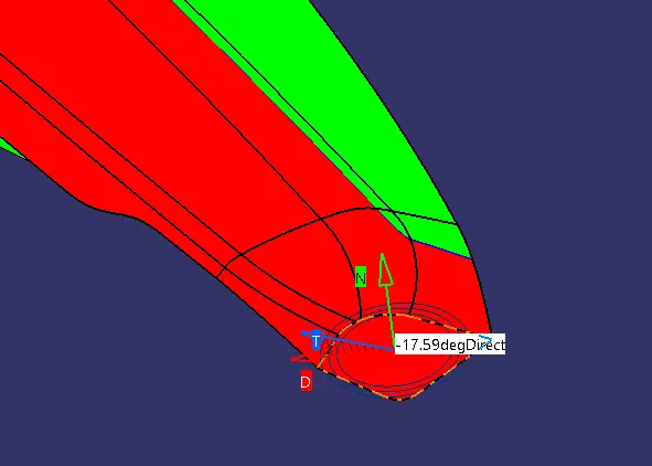
Draft analysis of the completed Arm rest plastic model.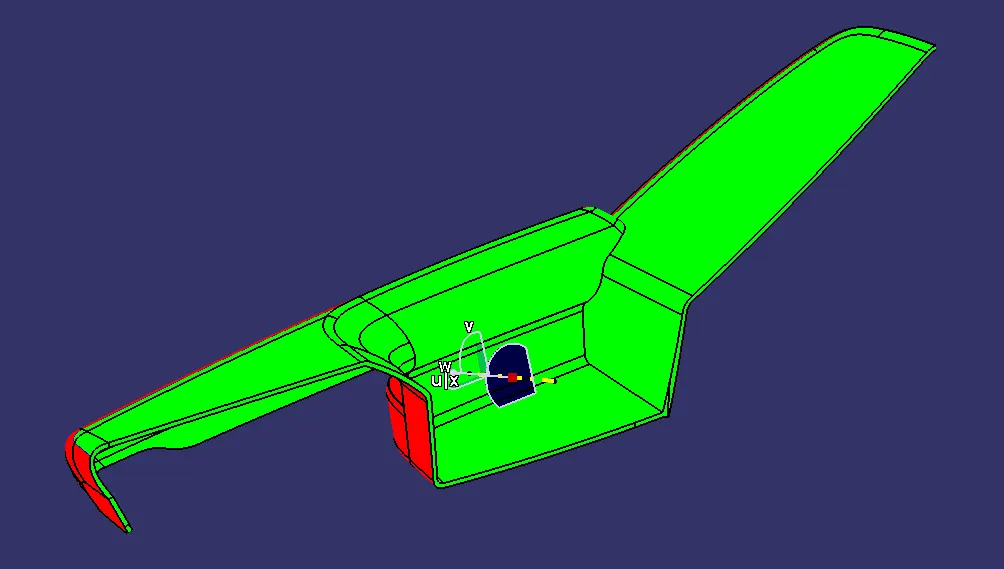
Draft analysis of the lower substrate class A surface:
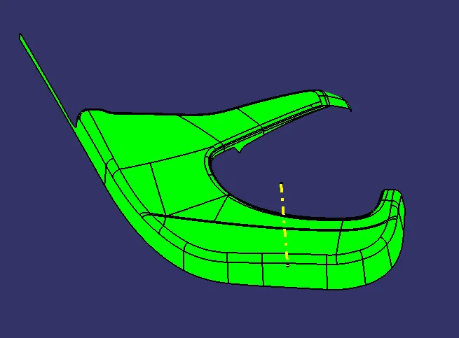
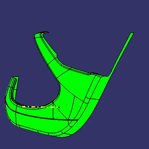
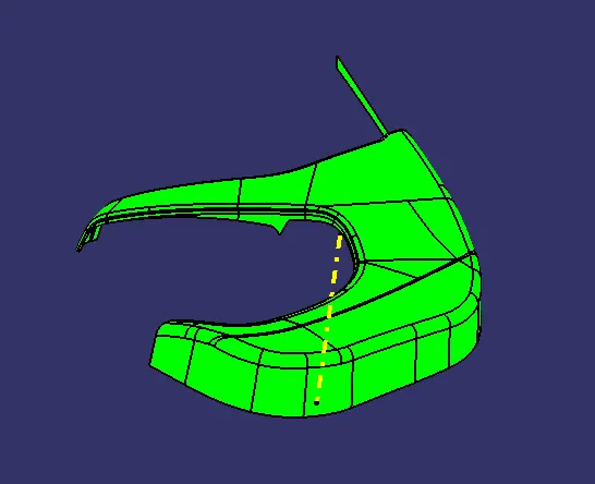
Draft analysis of the lower substrate plastic model:
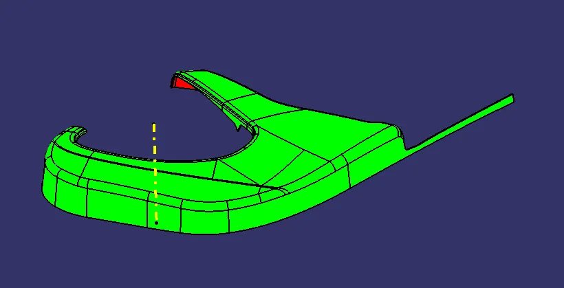
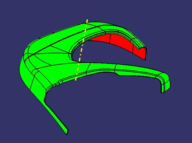
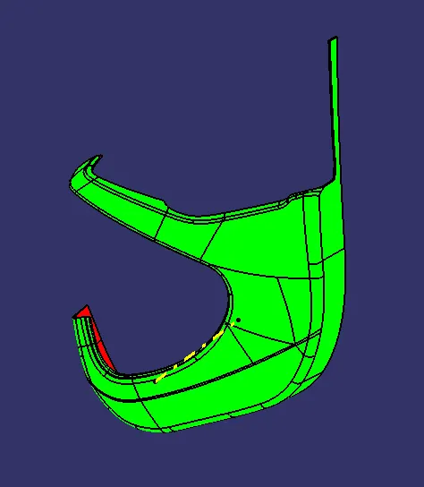
Draft analysis of the upper map pocket class A surface:
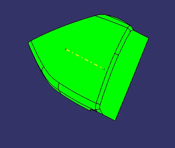
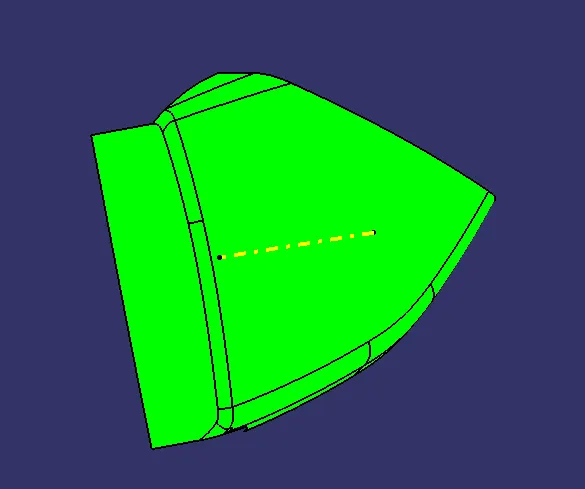
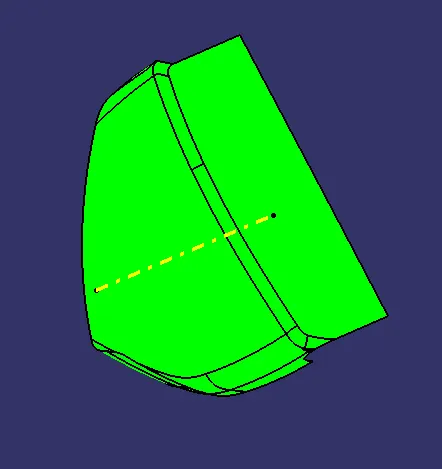
Draft analysis of the upper map pocket plastic model:
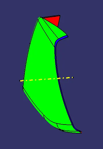
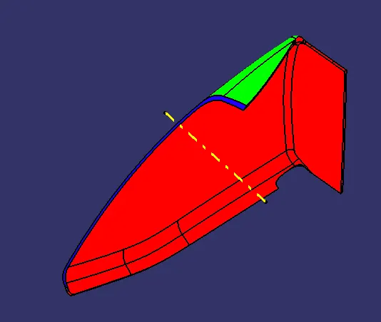
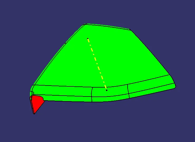
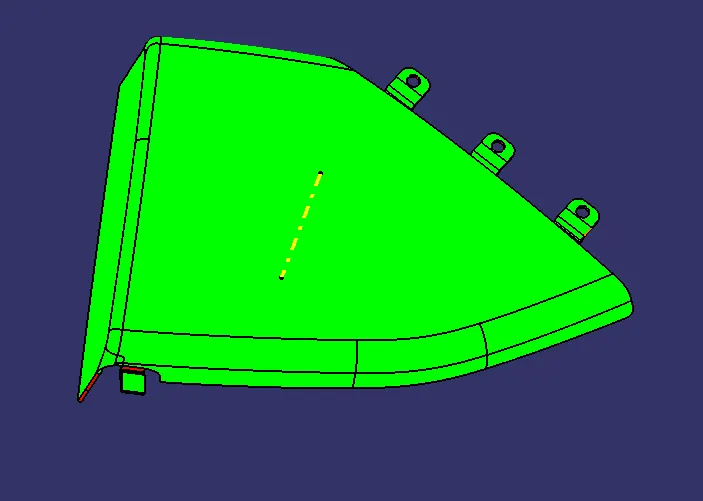
Draft analysis of the lower map pocket class A surface:
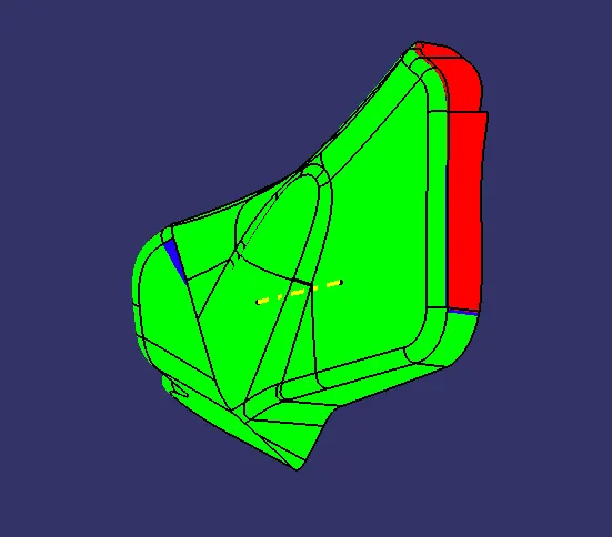
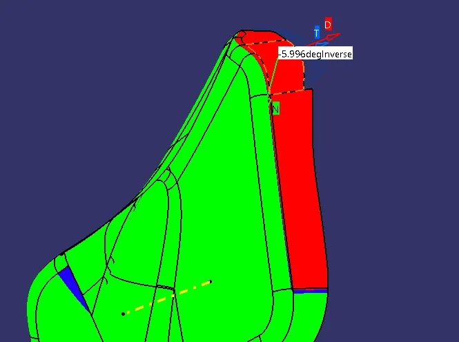
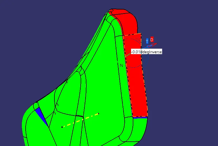
Draft analysis of the lower map pocket plastic model:
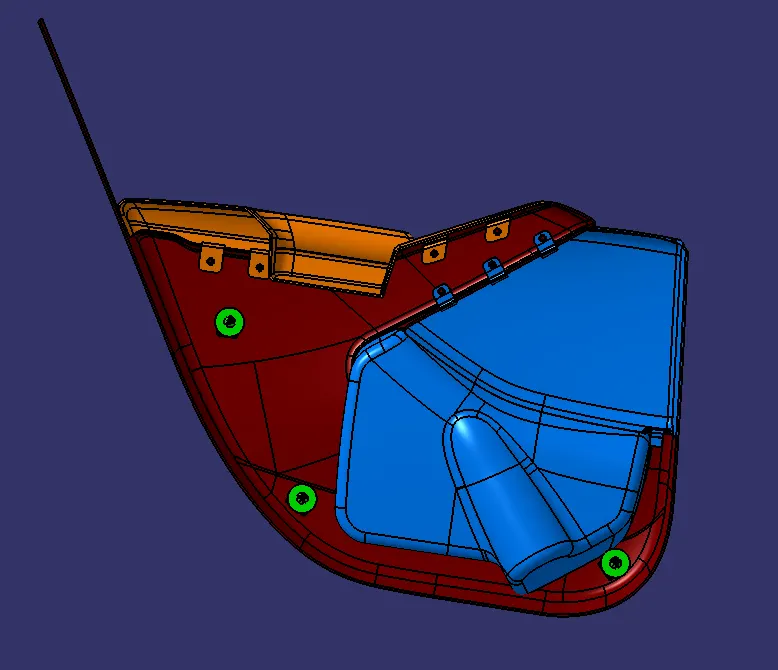
Final assembly of all the plastic parts along with its features:
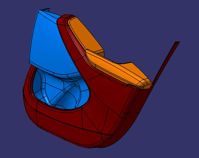
Parting Line
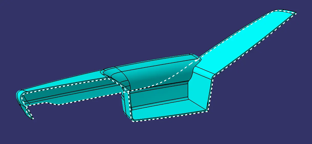
The parting line is the visible seam or line where the two halves of the mold meet and separate during the molding process. This is where the mold is divided, and the molded part is subsequently ejected. The parting line is a crucial aspect of mold design, impacting the final shape and appearance of the molded part.
Important points:
- Parting line should always form on the class B surface or the surface the component which dosent effect the surface finish of the component.
- The parting line should not be formed at the class A surface as it the most vulnarable location for the formation of the defects.
- Functional Requirements: Ensure the parting line does not interfere with mechanical functionality or structural integrity.
Mold Complexity: Place the parting line in a location that minimizes undercuts and allows for easier mold release.
Surface Finish: Avoid highly visible areas where the parting line could impact aesthetics.
Draft Angle Considerations: Align the parting line with natural draft angles to facilitate mold separation.
Assembly and Fitment: Ensure mating parts align properly without gaps or mismatches due to the parting line.
Material Flow: Optimize for uniform material distribution to prevent defects like sink marks or warping.