Week 12- Final project
DESIGN REPORT OF DOOR TRIM PANEL
Introduction:
The door trims are the interior parts that contain most of the controls and decorative parts the door trim comprises of various components such as the arm rest, map pocket, switch bezel, speaker and other electronic regulators and aesthetic trims designed in a way to enhance the user experience of the driver and the passenger.
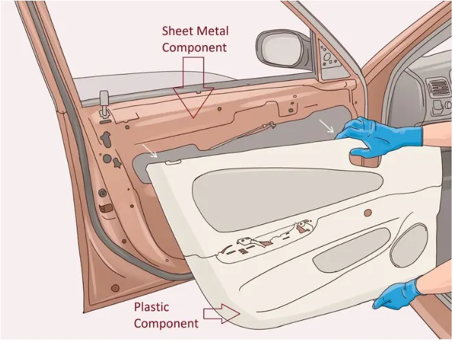
The plastic trim is attached to the sheet metal component which is the door inner with the help of various engineering features such as push clips, heat stakes etc. In this project, we are going to design a door trim’s components like Arm rest, Lower map pocket, Upper map pocket & Lower substrate. After designing the components, we are going to do the draft analysis for every component.
Draft Analysis is the process of analysing the designed plastic part if it has the drafting angles as per the requirement. In CATIA, draft analysis is done by the tool called Feature Draft Analysis. It shows the different draft angles available at different parts and says if it meets the requirement or not by various colour codes.
Objective:
· Creation of tooling axis and perform draft analysis on the given class A surface.
· Creation of Class B and Class C surface. After creation of Class A, B and C surface trim all together and use close surface option to make solid body.
· Creating attaching feature according to master section such as flanges heat stakes.
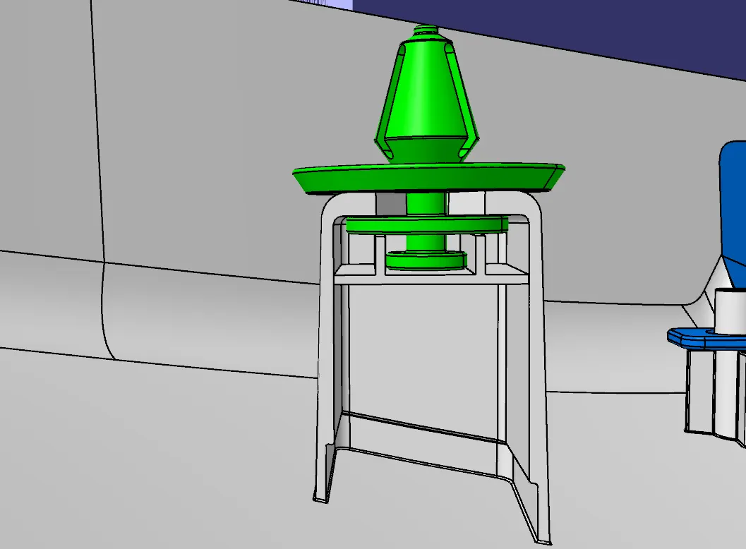
· Creation of Engineering features like Pushpins, Heat stakes, Ribs, Doghouse, Locators wherever required with their design guidelines.
· To preform draft analysis for each designed component.
· Assemble all part’s together with the push pins.
Procedure:
Step 1- Do inspection on Class A surface:
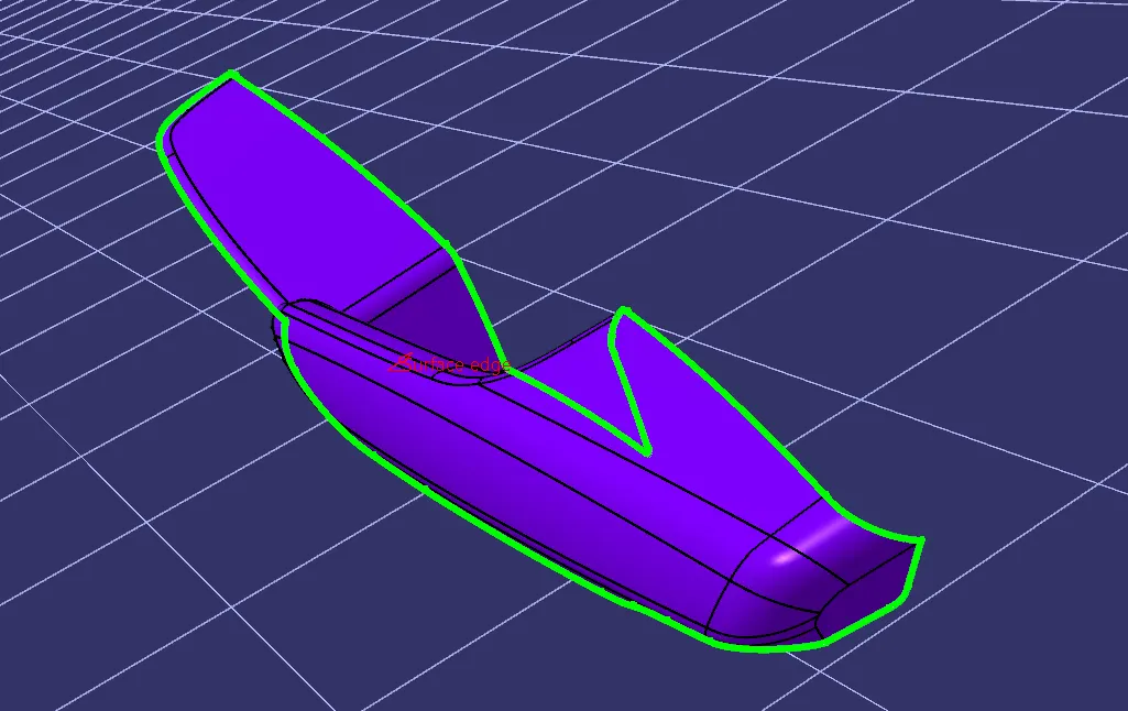
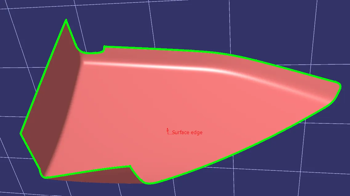
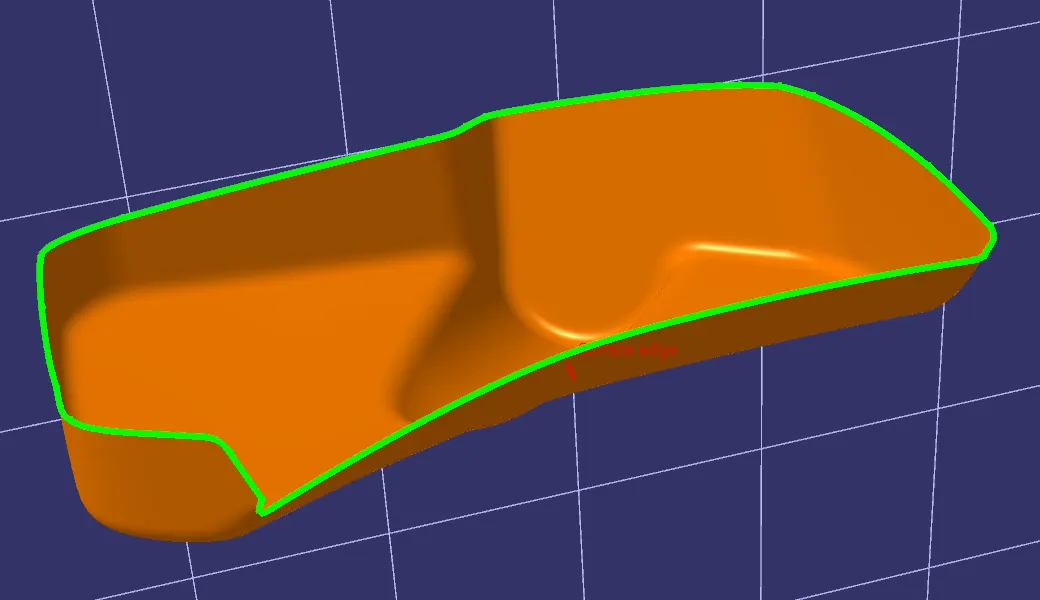
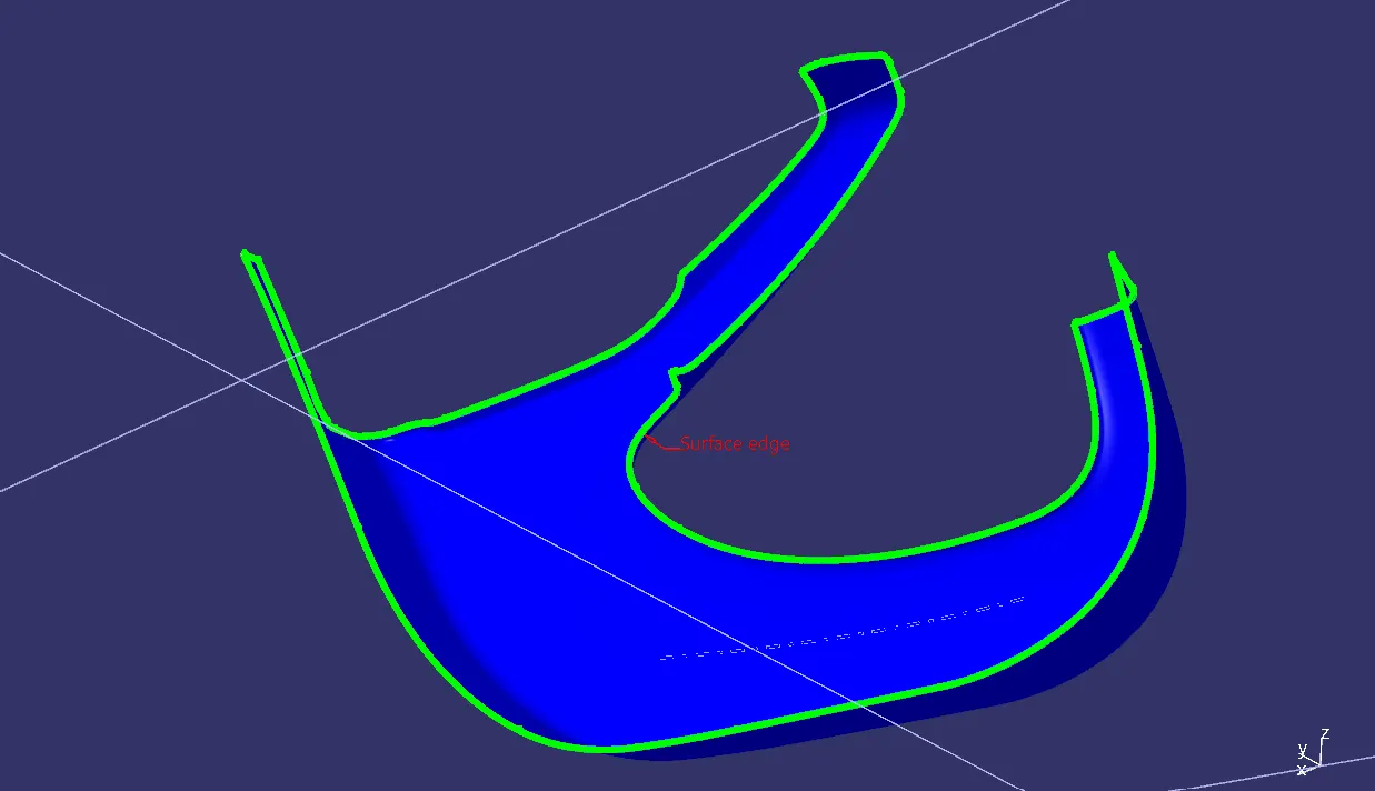
The given part (class A) is first checked for its boundary to find if there are any gaps or openings or discontinuity in the boundary. If there is any boundary you need to improve the quality of the surface before go to further.
After completing the boundary check insert a point at almost the symmetric centre of the part and insert a coordinate system at the point. The coordinate system should be facing in all directions the same as the default coordinate system.
Step 2- Creation of Tooling Axis:
Main Tooling Axis - The main tooling axis, often referred to as the "A-axis" or "primary axis," serves as the central point around which the core and cavity halves of the mould rotate or move during the moulding process. This primary axis is typically aligned with the centreline of the mould and corresponds to the primary movement of the moulding machine. The main tooling axis plays a fundamental role in the basic operation of the injection moulding machine by allowing the mould to open and close. This opening and closing action creates the necessary space for injecting molten plastic into the cavity and subsequently ejecting the finished part after cooling and solidification.
Side Core Tooling Axis - The side core tooling axis, often referred to as the "B-axis" or "secondary axis," is an additional axis employed in more complex moulds, especially when the part design includes features that cannot be formed through the simple opening and closing of the mould. The side core tooling axis facilitates the movement of side cores or slides within the mould. These side cores are movable components that are crucial for creating undercuts or complex features on the part by moving perpendicular to the main tooling axis. Side cores are typically utilized when the part design includes features like holes, threads, or undercuts that cannot be directly achieved through the mould’s main movement. By coordinating the B-axis movement with the A-axis movement, intricate part geometries can be produced, expanding the capabilities of plastic injection moulding for manufacturing complex plastic components.
Before actually creating the tooling axis, we need to create two dummy tooling axes on the class A surface at a point we created earlier. Then by using bisecting line command we need to find the final tooling axis.
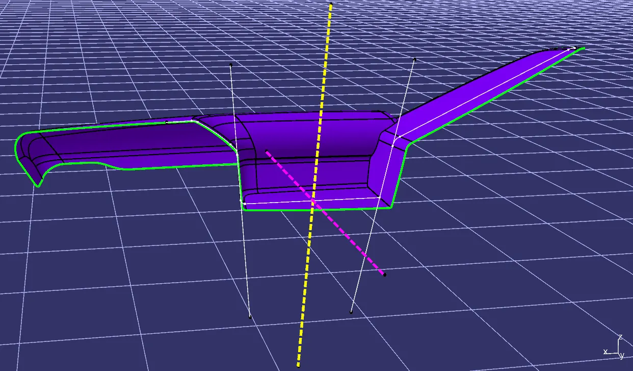
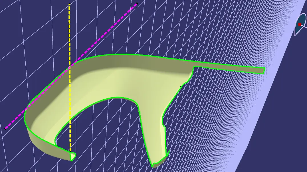
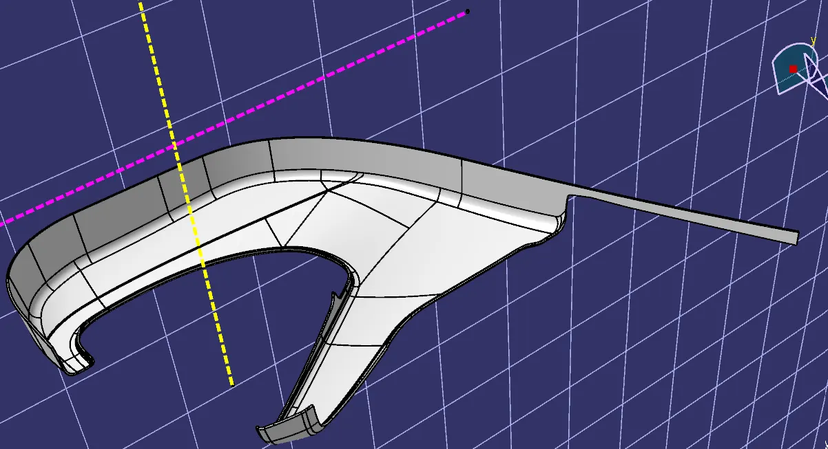
I. ARM REST - First do create dummy axis on the XZ plane, by taken reference from the class a surface using intersection command. With that reference lines by using bisecting line command, we can create dummy tooling axis for the XZ plane. In this case, Dummy tooling axis itself cleared draft test for the required faces on the part. So, we consider it as main tooling axis. It can be made bold and the colour can be changed for better visibility (yellow color).
For this part, we need to create side tooling axis. For that create a point on coordinate system and extend it on Y direction. Created dummy axis cleared draft test. So, we fix this as Side tooling axis. It can be made bold and the colour can be changed for better visibility (pink color).
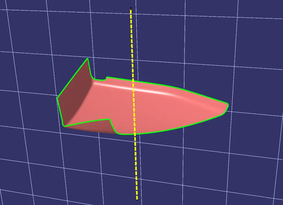
II. UPPER MAP POCKET – First do create dummy tooling axis on Y axis. The created dummy tooling axis itself cleared draft test. So, we consider it as main tooling axis. It can be made bold and the colour can be changed for better visibility.
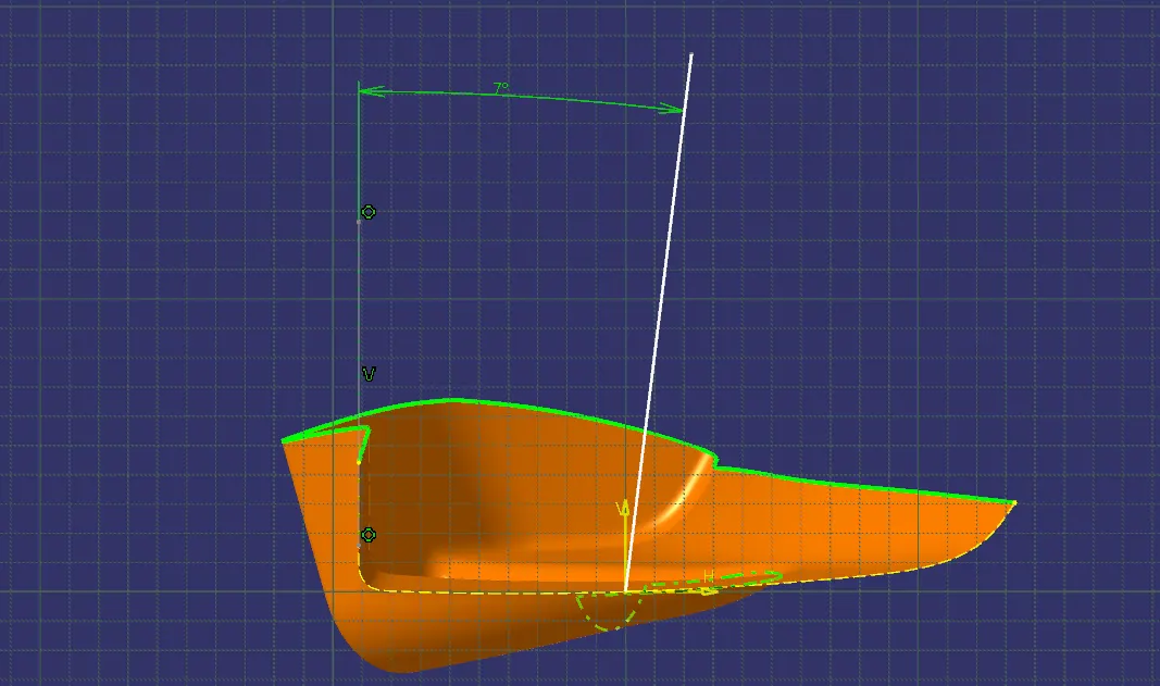
III. LOWER MAP POCKET(BOTTLE HOLDER) - Create a dummy tooling axis on the YZ plane by taking reference from the class A surface. Since there is only one intersection line, a dummy tooling axis is drawn at 7 degrees from the reference line at the point we created earlier. The below images show the dummy tooling axis for the YZ plane.
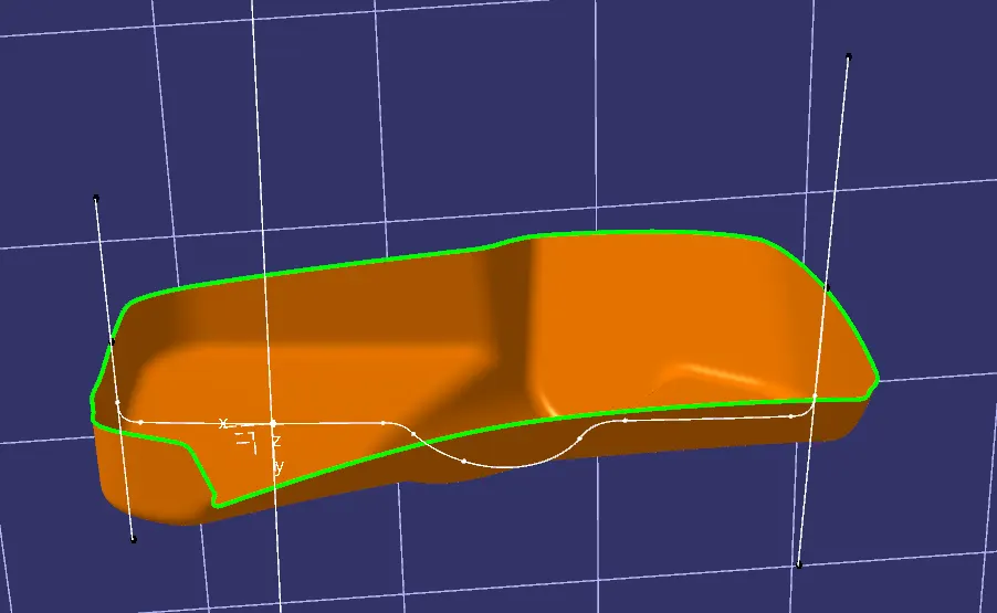
Then create dummy axis on the XY plane, by taken reference from the class a surface. With that reference lines by using bisecting line command, we can create dummy tooling axis for the XY plane. The below images show the dummy tooling axis for XY plane.
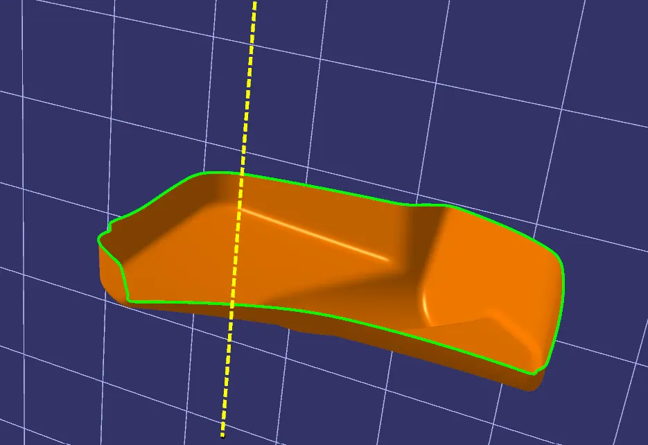
Now, using the two dummy tooling axes, use the bisecting line command to create a Main tooling axis. It can be made bold and the colour can be changed for better visibility.
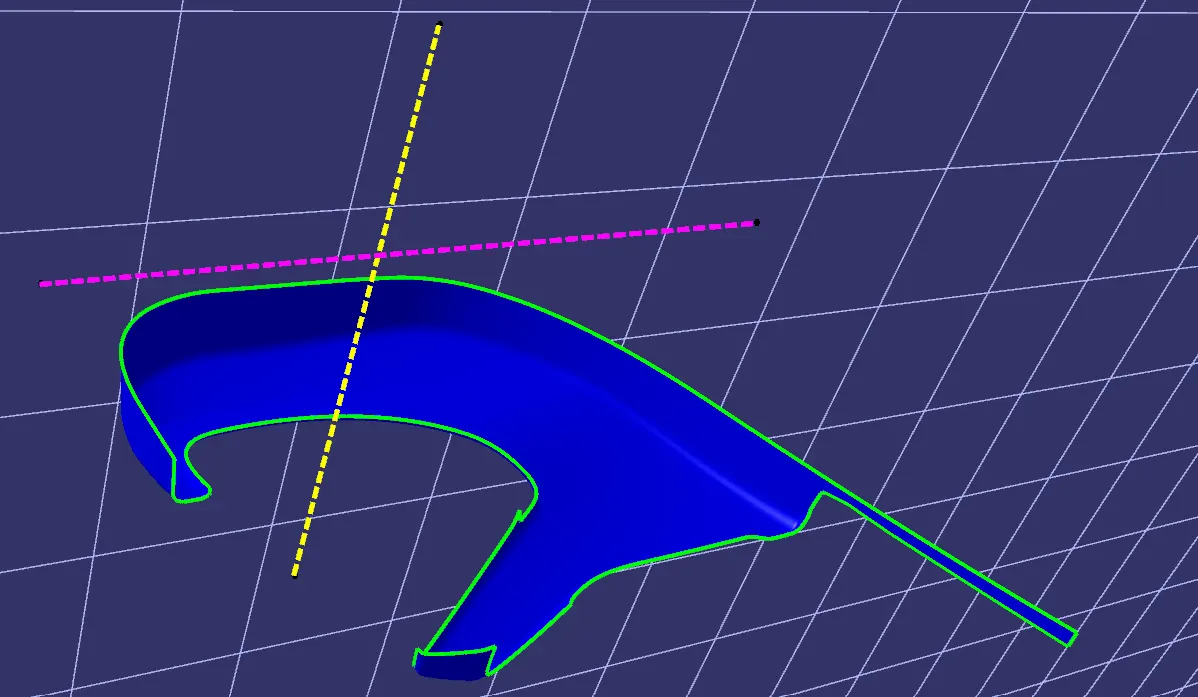
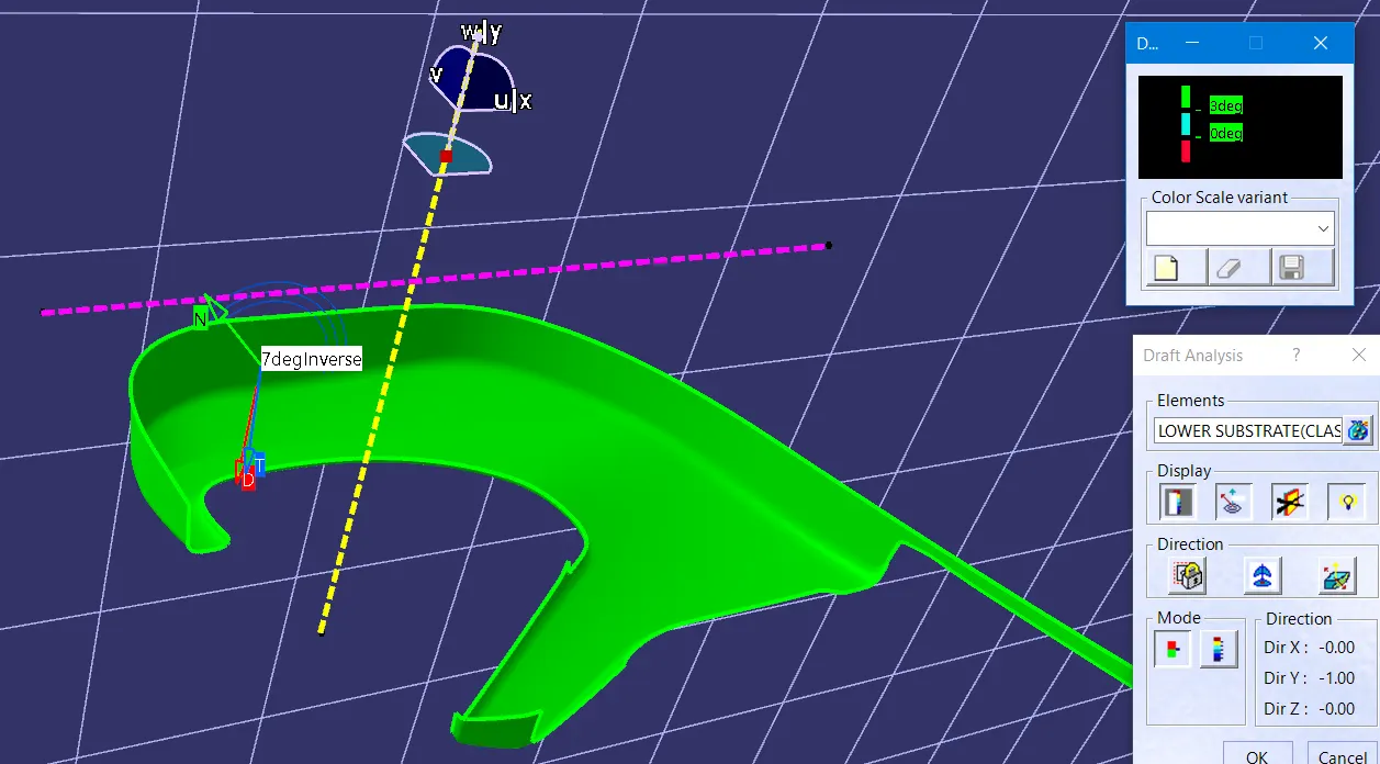
IV. LOWER SUBSTRATE - First do create dummy tooling axis on Y axis by using point and direction command. The created dummy tooling axis itself cleared draft test. So, we consider it as main tooling axis. It can be made bold and the colour can be changed for better visibility(yellow).
For the dog house in the lower substrate, we need to create a side core tooling axis. For that create a dummy tooling axis on X axis by using point and direction command. The created dummy tooling axis itself cleared draft test. So, we consider it as side tooling axis. It can be made bold and the colour can be changed for better visibility(pink).
Step 3 – Do draft analysis for the Class A surface:
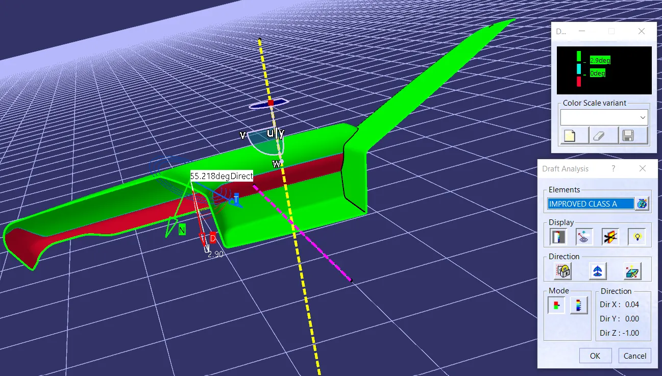
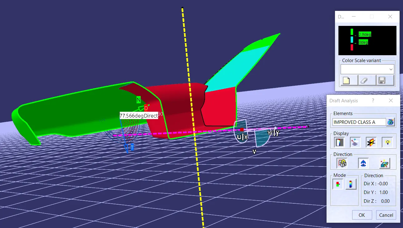
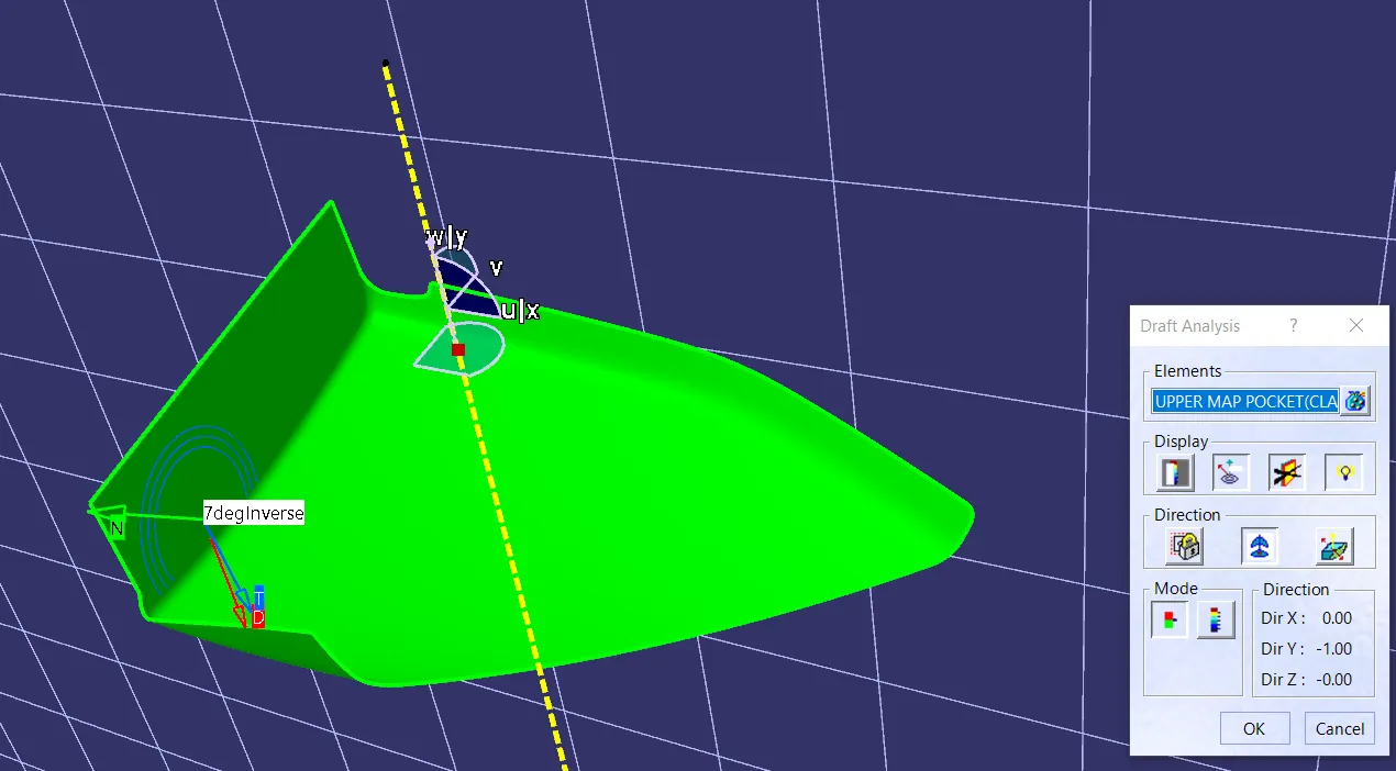
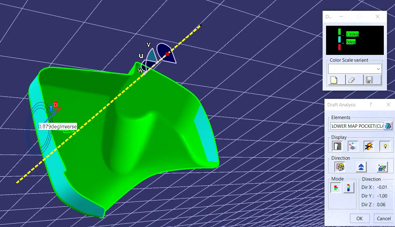
By doing this analysis some areas are showing red color. We need to inform about it to the concern CLASS A design team for solving the issue.
Arm rest
Upper map pocket
Lower map pocket
Lower substrate
Step 4 – Creation of Class B surface:
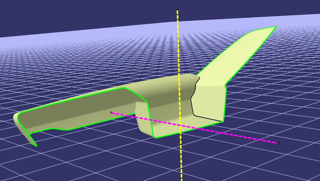
Class B surfaces are of lower quality compared to Class A but are still visually acceptable for many applications. They are used for parts where aesthetics is important but not as critical as in Class A surfaces. Characteristics of Class B surfaces include good surface finish with minimal imperfections, tolerances that are not as tight as Class A surfaces, and some visible parting lines and minor imperfections that may be acceptable.
Process involved to create Class B surface are,
· First insert a geometrical set for creating Class B Surface and Offset the class A for required dimension according to the master section.
· Create the missing patches and join to make the class B surface.
· To make the B surface Extract, Extrude, Extrapolate, Boundary, Smooth curve, Multi section and Fill commands were used.
· Extrapolate the boundary to make intersection with Class C surface.
Arm rest
Upper map pocket
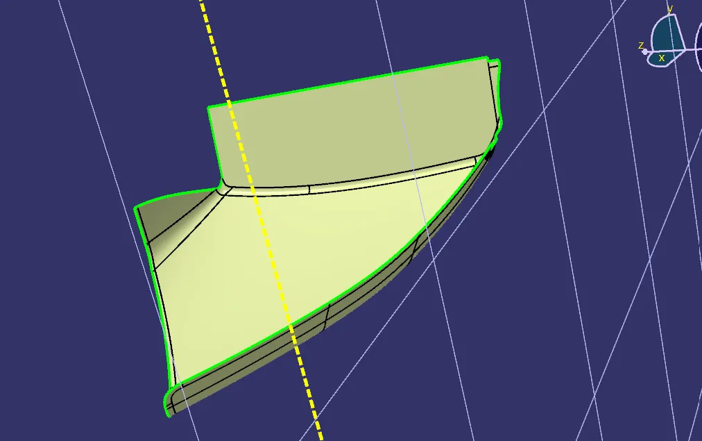
Lower map pocket
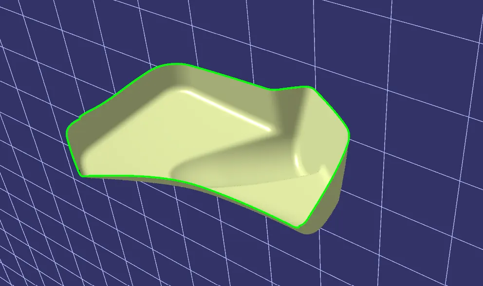
Lower substrate
Step 5 – Creation of Class C surface:
Class C surfaces are functional surfaces that do not have strict aesthetic requirements. They are used for parts where appearance is not a primary concern, often because they are hidden from view or serve a structural or functional purpose rather than an aesthetic one. Characteristics of Class C surfaces include being functional but may have rougher finishes and visible imperfections, tolerances that may be relatively loose compared to Class A and Class B surfaces, and typically, less emphasis on achieving perfect surface quality, as long as the part meets its functional requirements.
Process involved to create Class B surface are,
· Insert a geometrical set for class C surface creation.
· To make the Class C surface Boundary, Sweep, Multi section surface, Extrapolate, Trim and Join commands are used and the Class C surface was created with a draft of 3 degree.
Arm rest
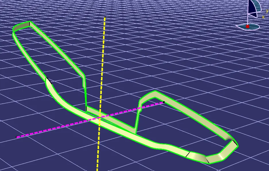
Upper map pocket
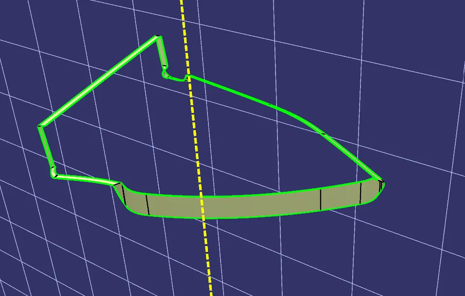
Lower map pocket
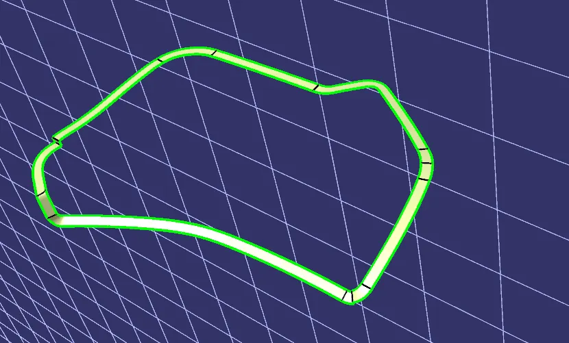
Lower substrate
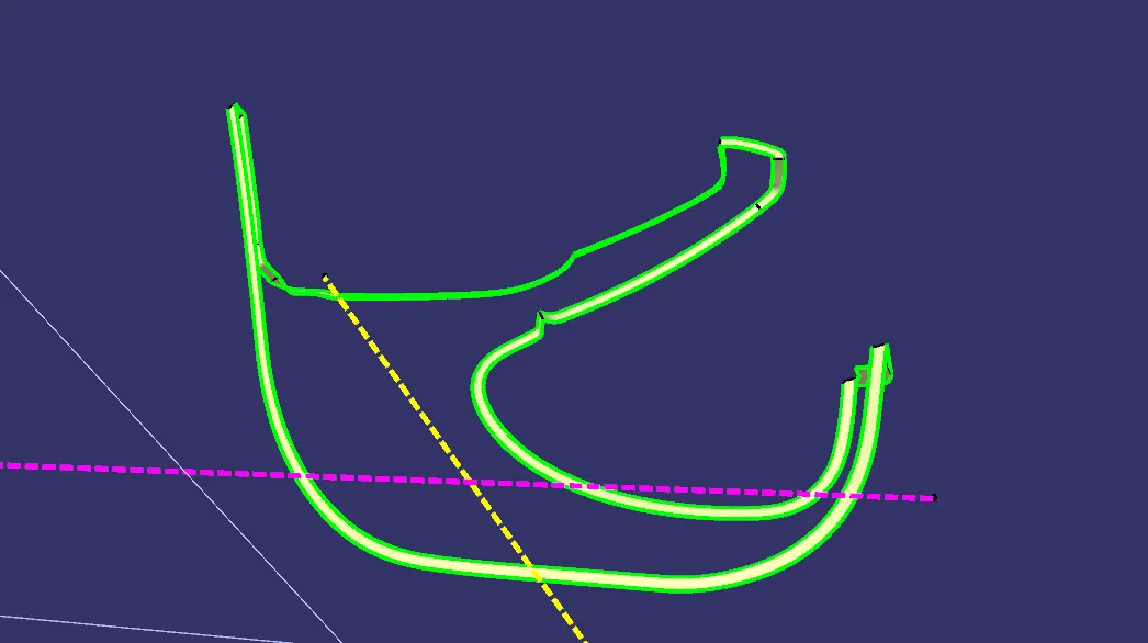
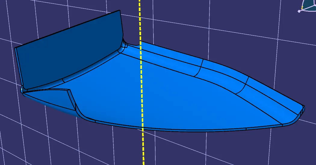
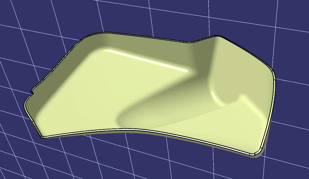
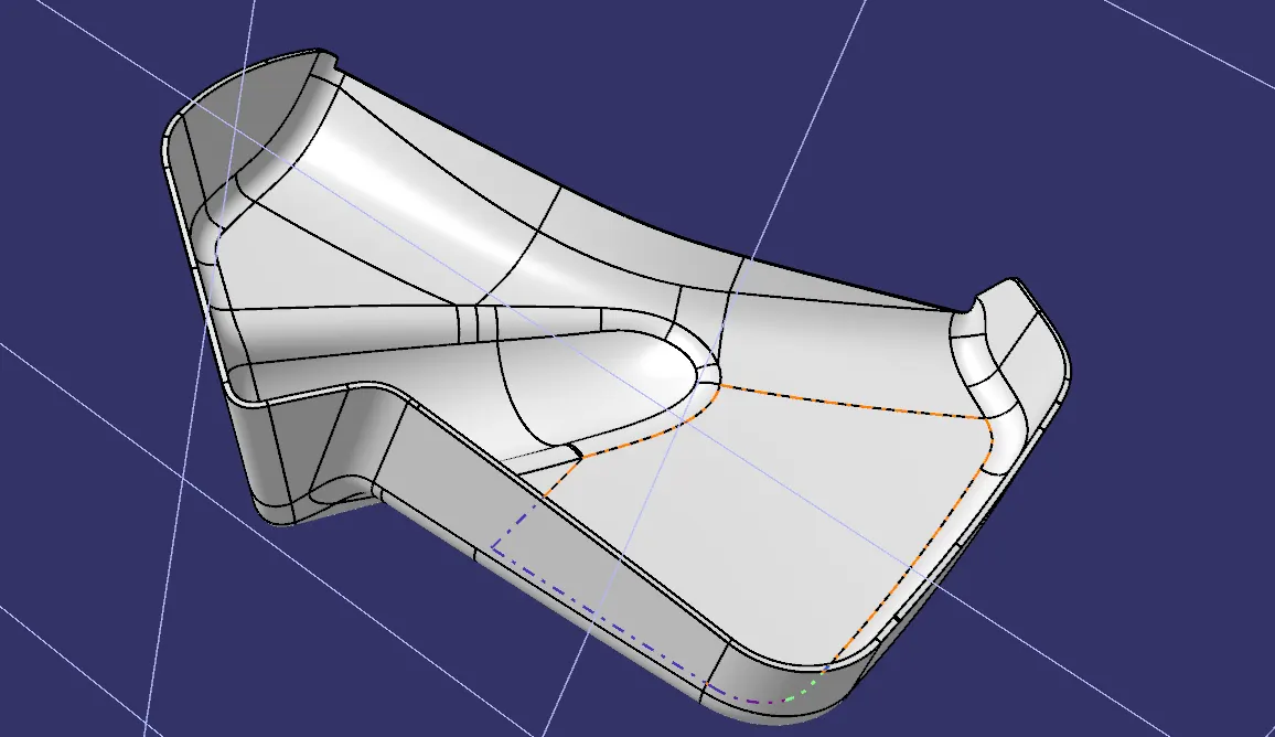
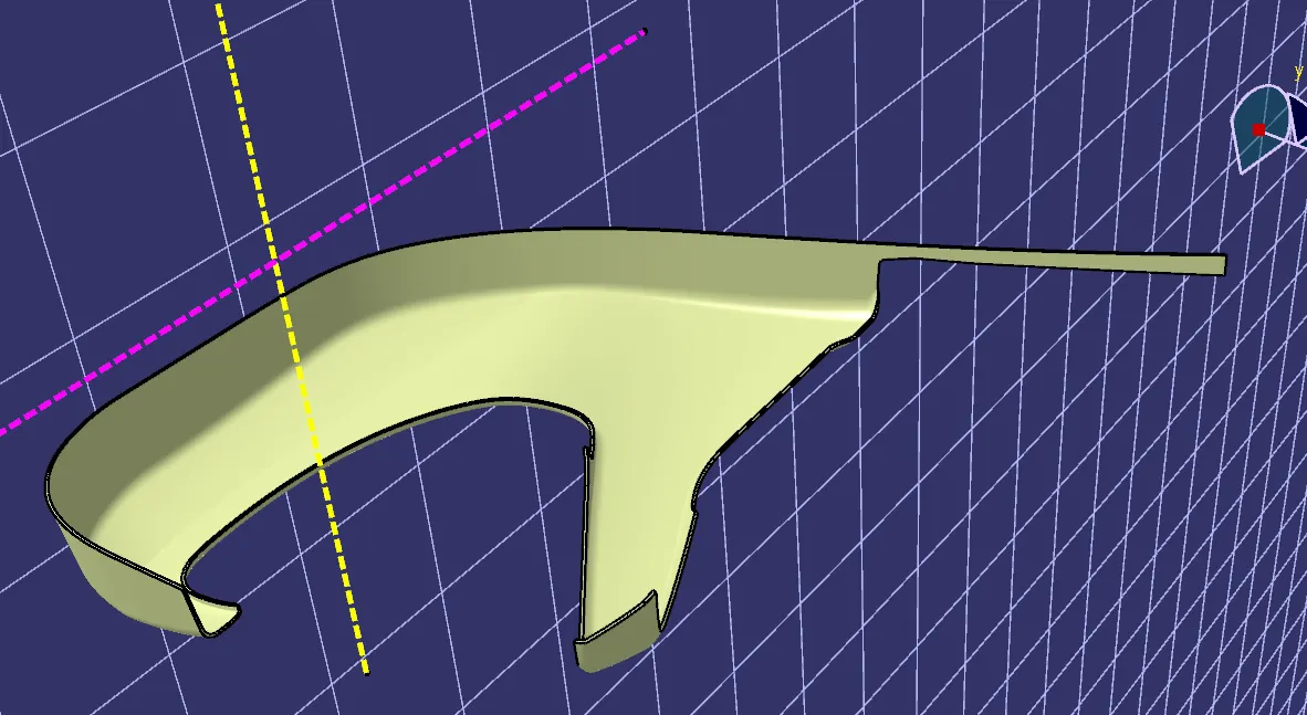
Step 6 – creation of solid body:
· First attach Class A & C surface with join command.
· Create closed surface by trimming the Class A & C surface with Class B surface.
· Switch to part design and by using closed surface command to make the solid body of required part.
· After making the solid body conducted the draft analysis.
Arm rest
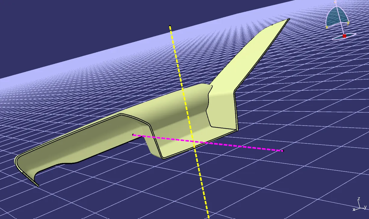
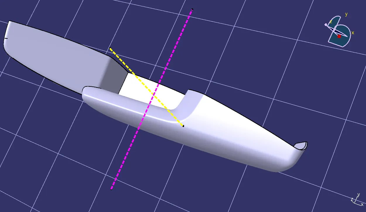
Upper map pocket
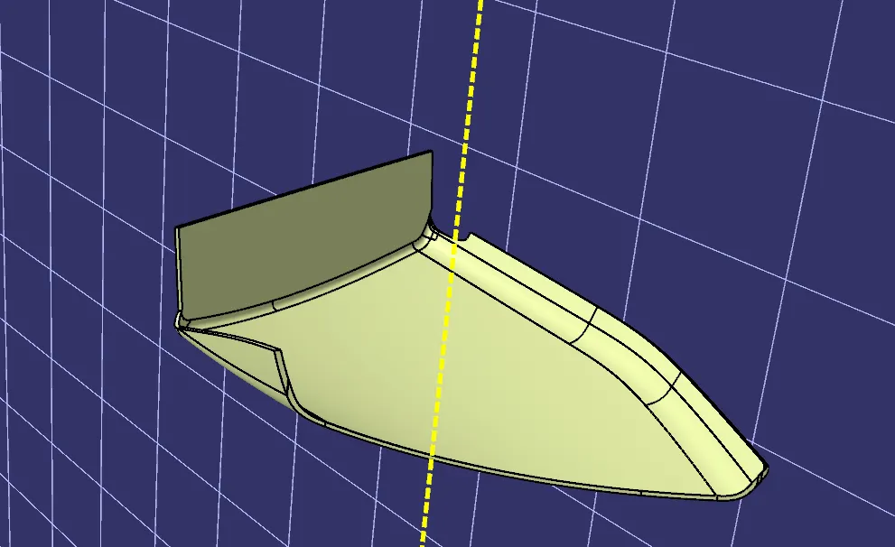
Lower map pocket
Lower substrate
Step 7 – Creation of Flange’s and Engineering feature’s:
Flanges:
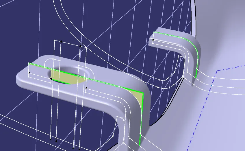
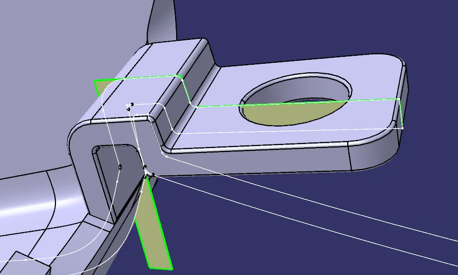
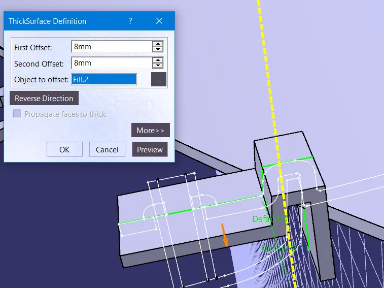
· Create flanges for all parts by taking reference from the master section.
· After creation of flanges use transformation feature command to pattern it for required quantity.
· Use Boolean operation to join them together and give fillets.
ARM REST
UPPER MAP POCKET
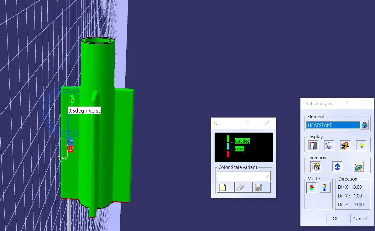
Heat stakes: (create heat stakes under design rules)
· Insert a geometrical set for creating the sketch, make the sketch for the heat stakes.
· Extrude the sketch using pad command and give draft of 0.5 degree.
· Make the sketch for rib and pad it and give fillet and chamfer. Union trims it with the heat stake.
· Copy and translate the heat stake made to required locations.
Locators: (create locators under design rules)
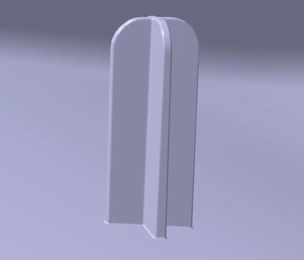
· The main purpose of locators is to facilitate proper locking of two components together while assembling and arrest the maximum degrees of freedom possible.
· These locators are similar to guide pins provided in mould.
· The two types of locators used are two way locator and four way locator.
Doghouse:
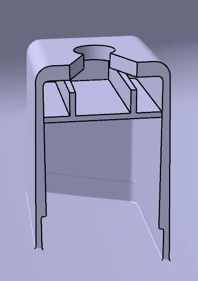
Design Rules for Doghouse are,
· C thickness should be 40% of the main wall thickness T
· Minimum width of the dog house is 12 mm.
· Height of B should be 3-6 mm
· Minimum draft value for the doghouse is 1.5 degree to tooling axis.
Procedure to create doghouse are,
· Insert geometrical set for creating doghouse.
· Make a side core tooling axis for providing draft.
· Extract the surface and add a point and plane on it to make sketch which will be extruded and thickened.
· Provide draft of 1.5 degree for the outer surface with main tooling axis and 0.5 degree for inside surface with side core tooling axis of the doghouse.
· Provide the edge fillets.
· Create the slot for push pin and screw/bolt by padding.
· Join the dog house using union trim to the main body and remove the slot.
Step 8 – Conduct draft analysis for the solid body:
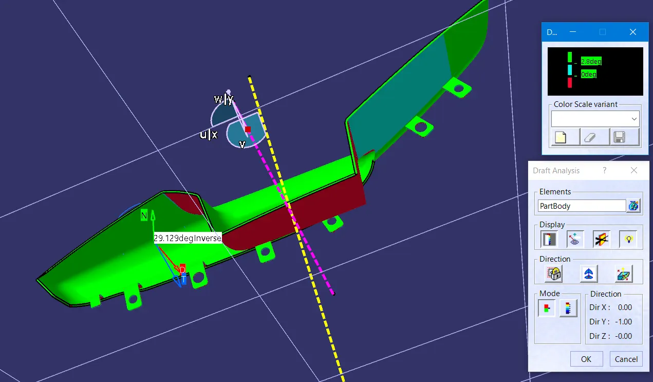
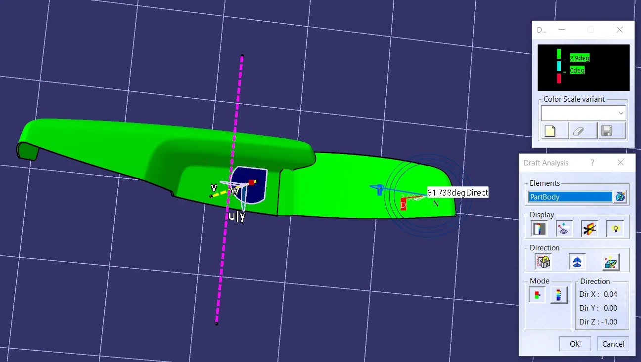
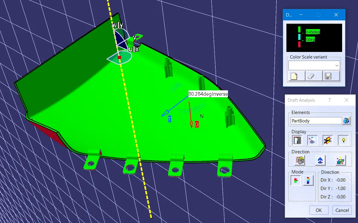
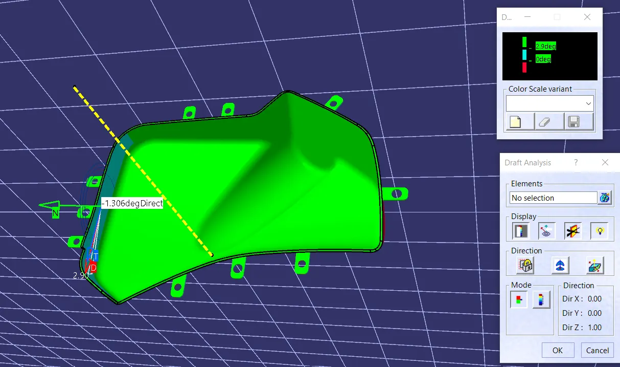
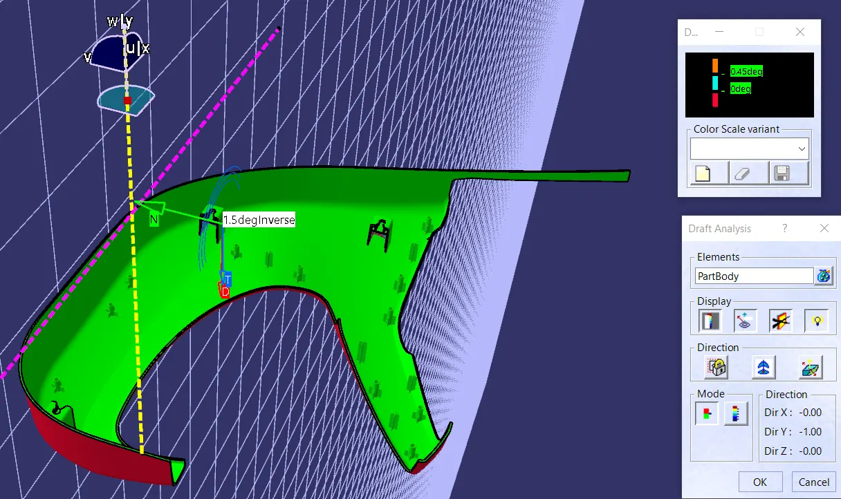
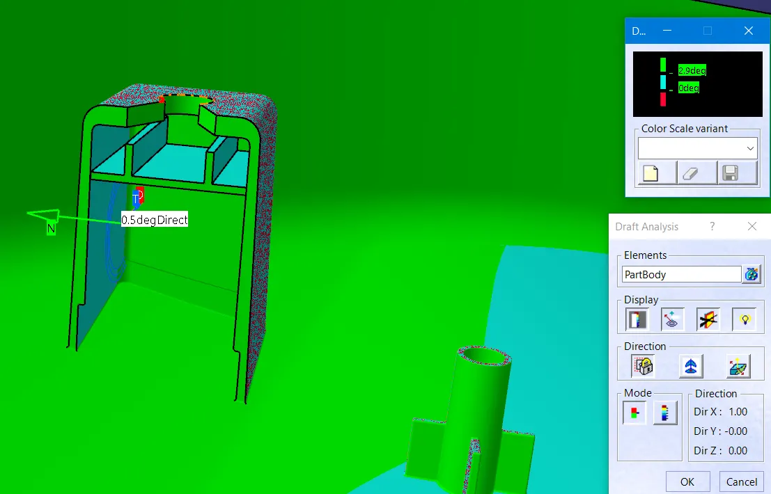
Now, perform the draft analysis of the all part one by one. To do so, go to Tools > Analysis > Feature Draft Analysis. This tool has three groups of options, namely mode, display, and direction. First, the second icon from the direction group is selected, and the red dot in the compass is clicked and dragged to the part to be drafted. The line in the dragged element is matched with the tooling axis, and it is locked using the first icon in the direction group. It will define the tooling axis direction and lock it.
Then click the required part. It will create different color’s on the main part. If the part is in green color, it shows the draft angle is ok. If it is not in the sense, then do correct the sketch of the tooling axis to correct it or check the commands used for creating the part.
The final result shows that all areas in the parts are maintained under 0.5 to 3.0 degree draft angle.
Each colour zones indicates each drafting angle,
· Green indicates within given draft angle,
· Blue indicates zero and
· Red indicates negative angle.
Arm rest
Upper map pocket
Lower map pocket
Lower substrate
Step 9 – Final assembly of door trim:
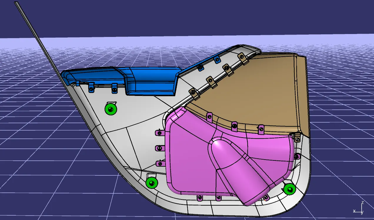
· After completion of the door panel part’s draft test.
· Open a new product file in assembly workbench.
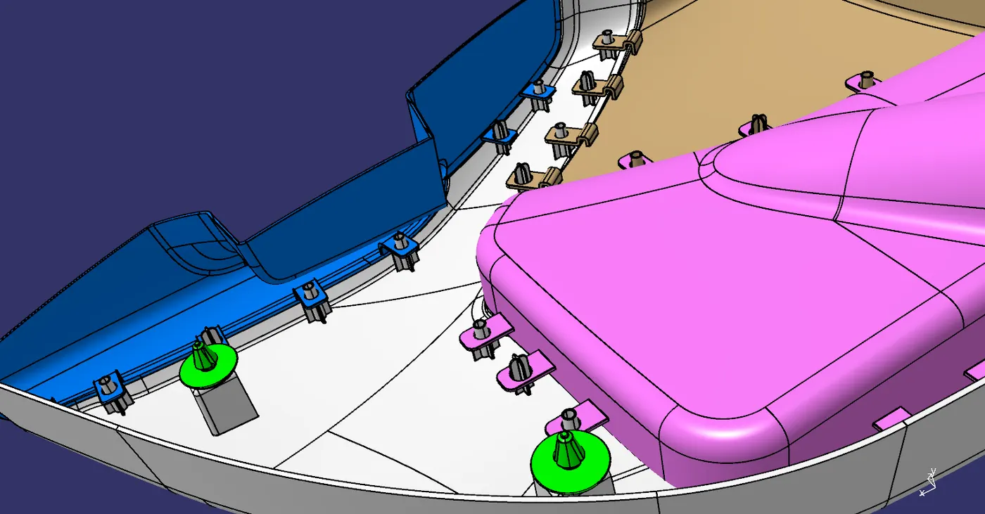
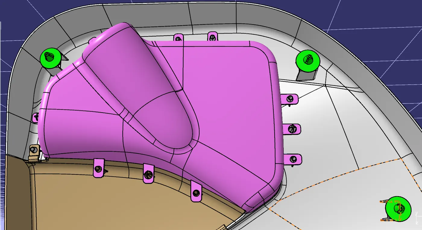
· First fix lower substrate as main part. After that assemble other parts to the lower substrate by using assembly constrains.
· After that assemble the push pin clip with the dog house to complete the Assembly.

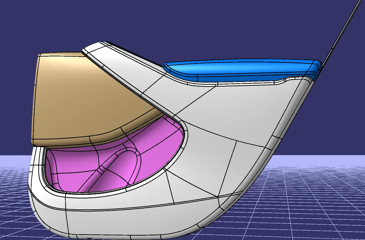
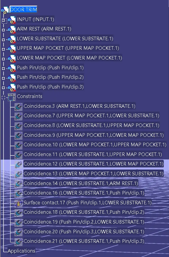
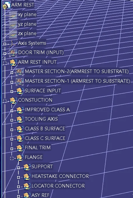
Tree structure:
Arm rest
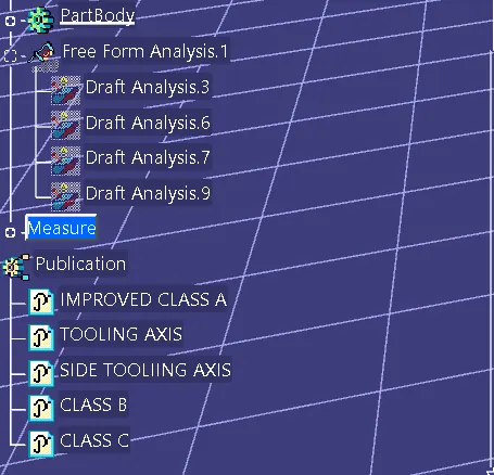
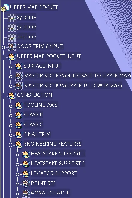
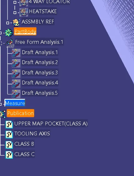
Upper map pocket
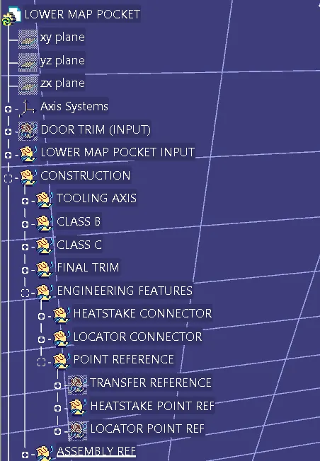
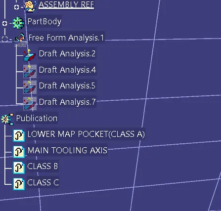
Lower map pocket
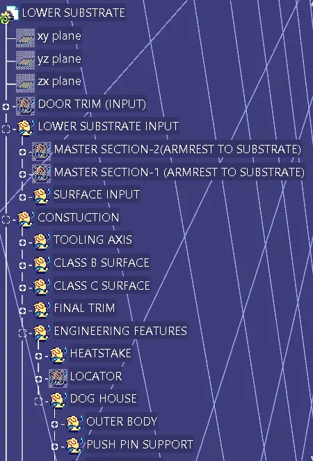
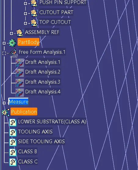
Lower substrate
Assembly