Week 12- Final project
Aim:
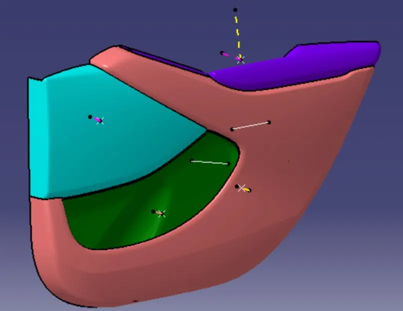
To create a CAD model of side door trim panel from given class A surfaces.
Objective:
1) Creation of side door trim panel from given class A surface . Apply thickness and use attachment features .
2) Creation of mountings and heat stakes from given master sections .
3) Creation of dog house and various attachment features using industry standards.
4) Performing draft analysis and ensuring the features and surfaces clear it .
Procedure:
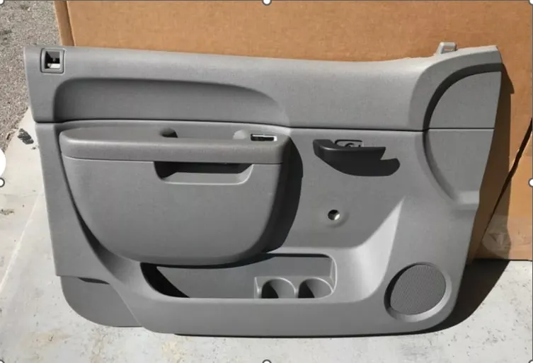
Below is an example of actual plastic door trim
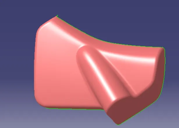
The given data comprises of four parts respectively
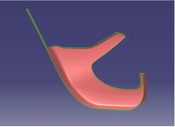
1. Lower Substrate
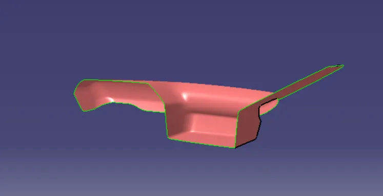
2. Door Armrest
3. Map Pocket
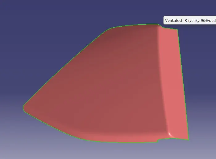
4. Bottle Holder
Steps to be followed for development of each component
1) Creation of tooling axis
2) Creation of class B surface
3) Creation of class C surface
4) Creation of closed body
5) Engineering Features
Tree Order
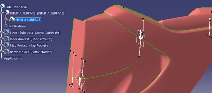
1) Creation of tooling axis
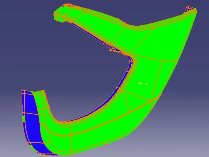
1. Lower Substrate
Main Demolding is created considering the surface boundary as parting of the A surface.
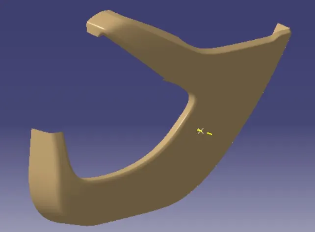
Draft analysis is done for the same to check for undercut.
2. Door Armrest
Main demolding is created using the same criteria of A surface boundary.
Pocket area cannot be cleared using main demolding.
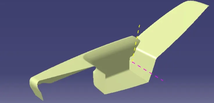
Slider direction is created based on the three perpendicular faces to be cleared for the pocket area.
Draft analysis is done for the same to check for undercut.
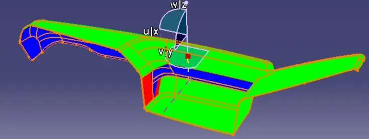
Slider direction draft analysis for clearing the pocket area.
3. Map Pocket
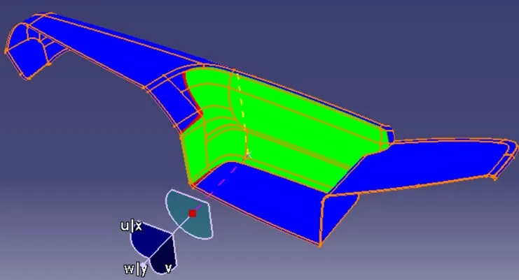
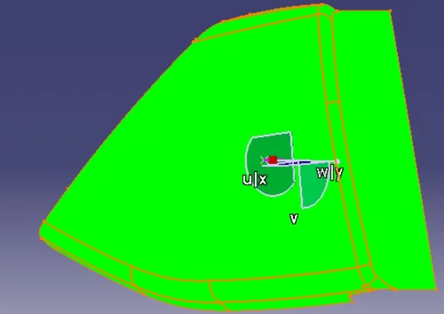
Main demolding is created using the same criteria of A surface boundary.
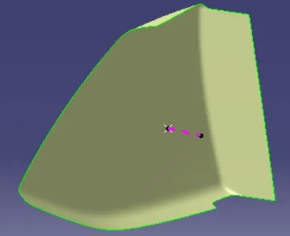
Draft analysis is done for the same to check for undercut.
4. Bottle Holder
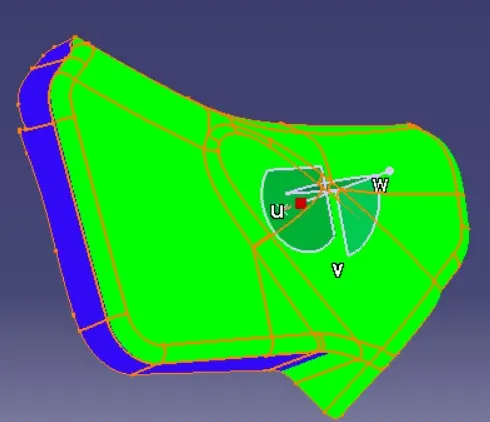
Main demolding is created using the same criteria of A surface boundary.
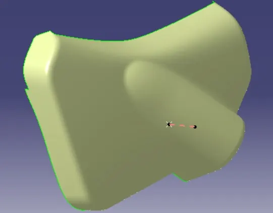
Draft analysis is done for the same to check for undercut.
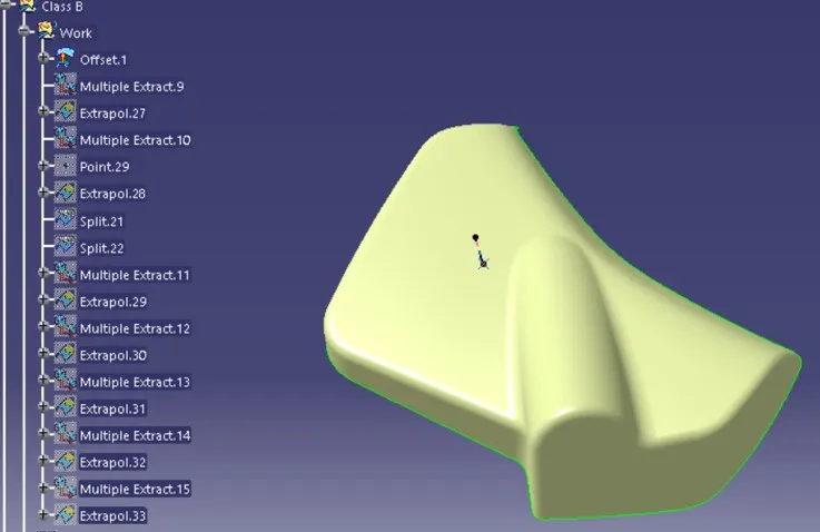
2) Creation of class B surface
1. Lower Substrate
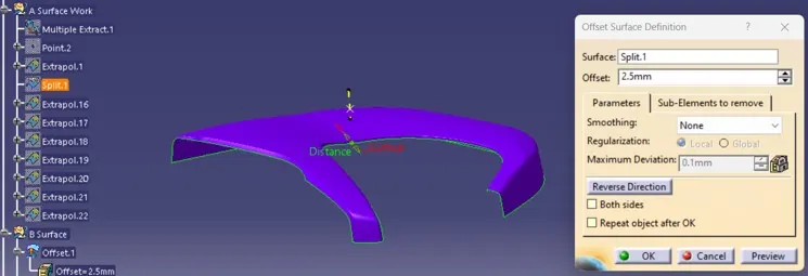
Class B surface is created by offsetting the class A surface.
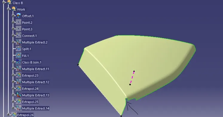
Tears in surface are corrected by usage of either fill, multi section or blend commands.
The created class B is extrapolated to incorporate trimming operation with class C surface.
2. Door Armrest
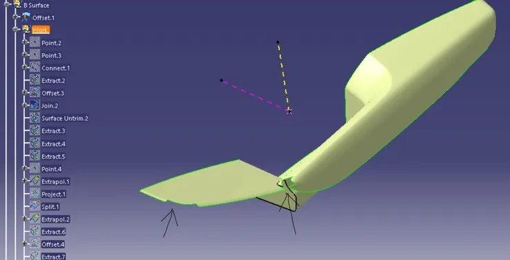
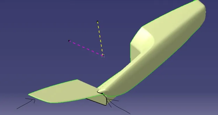
Class B surface is created by offsetting the class A surface.
Tears in surface are corrected by usage of either fill, multi section or blend commands.
The created class B is extrapolated to incorporate trimming operation with class C surface.
3. Map Pocket
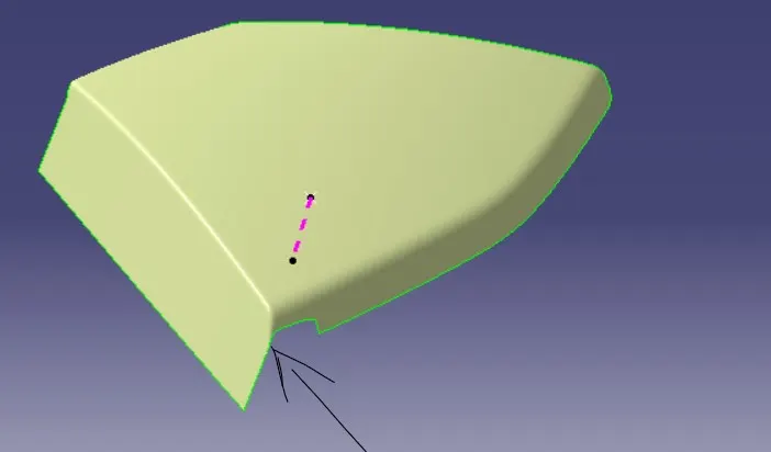
4. Bottle Holder
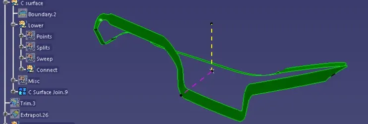
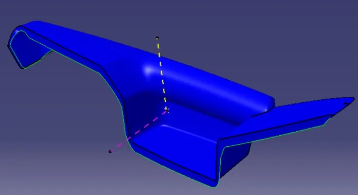
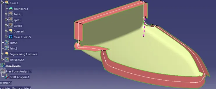
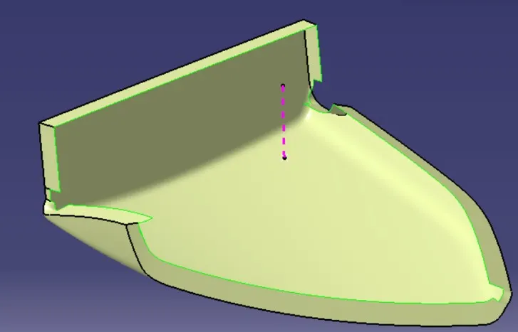
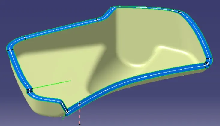
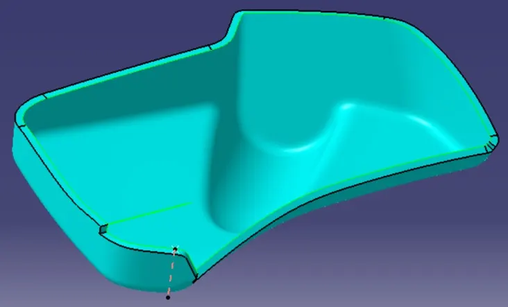
3) Creation of class C surface
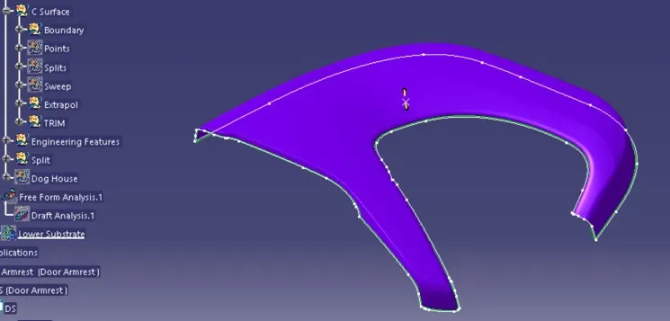
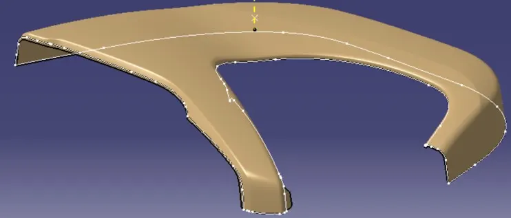
1. Lower Substrate
Class C is created by following the below process
Boundary < Splitting points < Splits < Sweep < Multi section / Trim
2. Door Armrest
3. Map Pocket
4. Bottle Holder
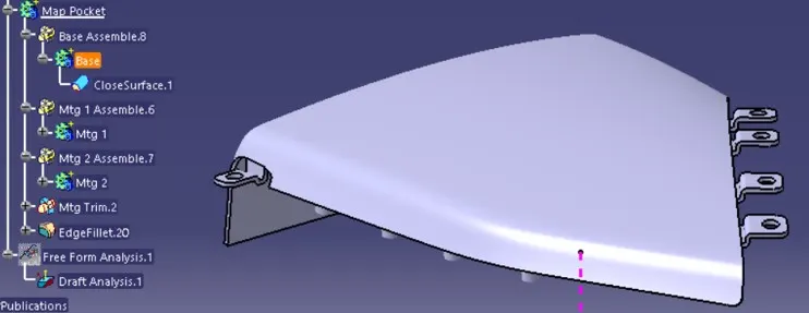
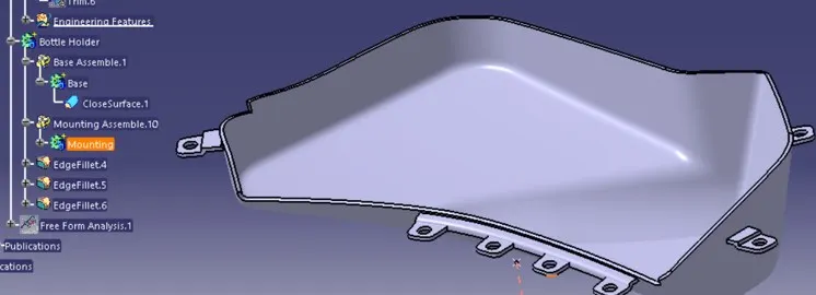
4) Creation of closed body
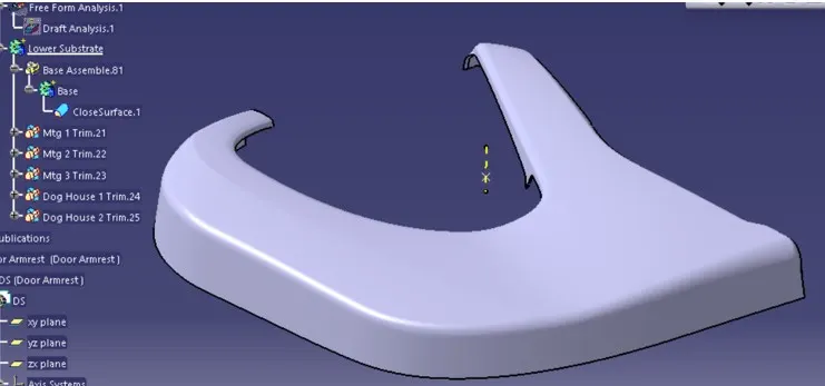
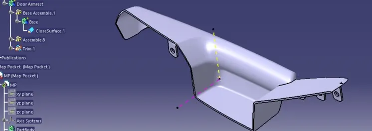
Closed body is created by trimming class A, class B, class C.
1. Lower Substrate
2. Door Armrest
3. Map Pocket
4. Bottle Holder
5) Engineering Features
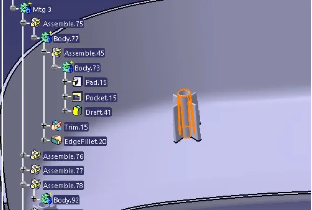
Heat stakes are created using part design modelling.
Base structure
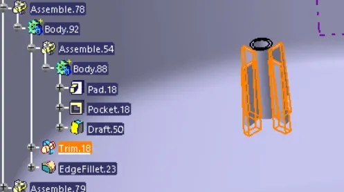
Strength rib structure
Dog house is created using generative shape design and part design modelling.
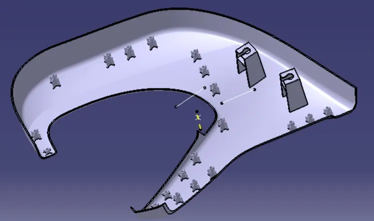
Lower substrate acts as a major part to which other parts are mounted.
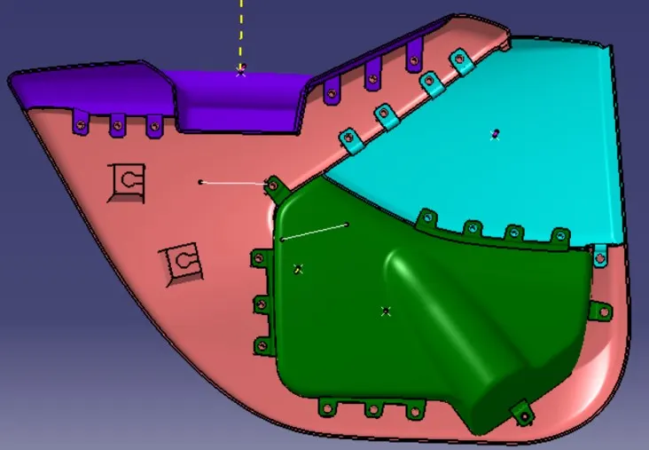
Heat stake mountings are created based on given section section by surface modelling.