Week 12- Final project
Development of a Door Trim panel
To Develop a Door trim lower panel from the provided Class A Surface and Master Sections
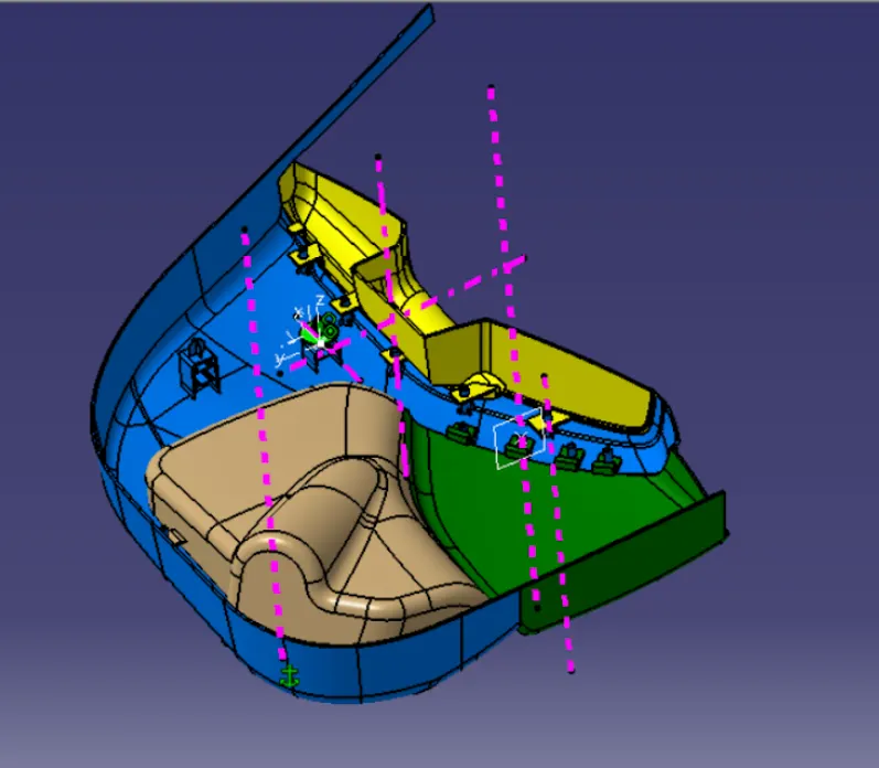
Inputs - Class A Surfaces of Lower Substrate, Arm Rest, Map Pocket, and Bottle holders along with the Master Sections and Pushpin
Parts were inserted into an assembly and the master section was taken out to create a separate file for easy selection
STEP 1: Draft Analysis of A surface:
To check the draft analysis of the provided Class A surfaces, the Tooling Axis is created, and the draft analysis is done
Tooling Axis creation - The tooling axis is created using point and direction and normal to the surface and the draft analysis is done for the parts using these tooling axis
STEP 2: Class B and Class C Surface Creation
Class B surface is created by offsetting 2.5 mm the class A surface and the gaps and errors formed during the offsetting operation are corrected using sweep, trim, etc
The Class C surfaces were created from Class A using the tooling axis, Sweeping with the tooling axis for surfaces perpendicular to the tooling axis and sweep with respect to surfaces that are parallel to the tooling axis
STEP 3 : Closed Body Creation:
The A, B, and C Surfaces are then trimmed to form a closed surface and the Closed surface option in part design is used to create the part
STEP 4: Engineering Features
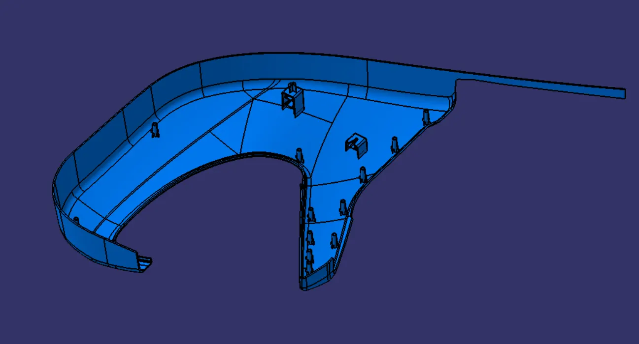
Part 1 : Lower Substrate
The lower substrate is the main part that we will attach to the BIW so it contains
Dog House with locators and Pushpin, Heatstakes for holding other parts
Heatstakes are created from the provided master sections and the Translation option was used to transfer it to the required position after a copy was generated
Drafting of 0.5 deg was provided to the heat stakes
A rib is created to support the heat stakes following the design principles of rib design
Dog house is created with ribs to support the Pushpin and 4-way locator
4-way locator is created above the dog house since the lower substrate has a flange so it will be impossible to build the locator from bottom
All the engineering features are Union trimmed to the main body and the final part was created
Draft Analysis for the final Part is done
Part 2 : Map pocket
The Map pocket contains Flanges for heat stakes and for attachments
The Flanges are created by following the Master Section by using the methods of Intersection, Sweep, extrude and trim
Surfaces are thickened using thicken command from the Part workbench
Part is split in the required size for which extruded surfaces are used
Then Holes for the heat stakes are created with a 0.5 mm clearance
0.5 deg of the draft is provided for all the features
All the engineering features are Union trimmed to the main body and the final part was created
Draft Analysis for the final Part is done
Part 3 :Bottle Holder
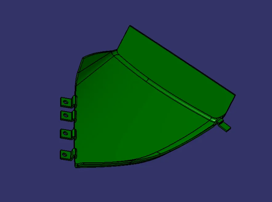
The Bottle Holder contains Flanges for heat stakes
The Flanges are created by following the Master Section by using the methods of Intersection, Sweep, extrude and trim
Surfaces are thickened using thicken command from the Part workbench
Part is split in the required size for which extruded surfaces are used
Then Holes for the heat stakes are created with a 0.5 mm clearance
0.5 deg of the draft is provided for all the features
All the engineering features are Union trimmed to the main body and the final part was created
Draft Analysis for the final Part is done
Part 4 : Arm Rest
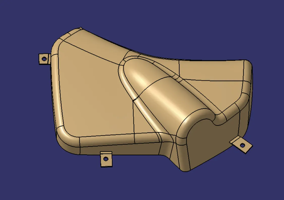
The Arm Rest contains Flanges for heat stakes and for attachments
The Flanges are created by following the Master Section by using the methods of Intersection, Sweep, extrude and trim
Surfaces are thickened using thicken command from the Part workbench
Part is split in the required size for which extruded surfaces are used
Then Holes for the heat stakes are created with a 0.5 mm clearance
0.5 deg of the draft is provided for all the features
All the engineering features are Union trimmed to the main body and the final part was created
Draft Analysis for the final Part is done
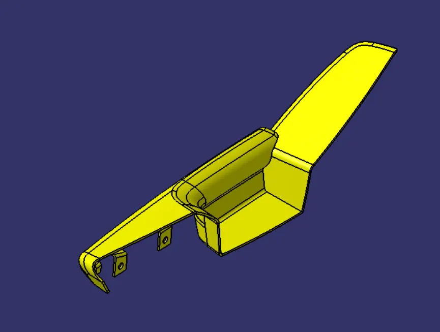
STEP 5 :Final Assembly and Push Pin
The lower substrates is fixed in the position to attach the push pin to the assembly
The Push pin is attached on the dog house