Week 12- Final project
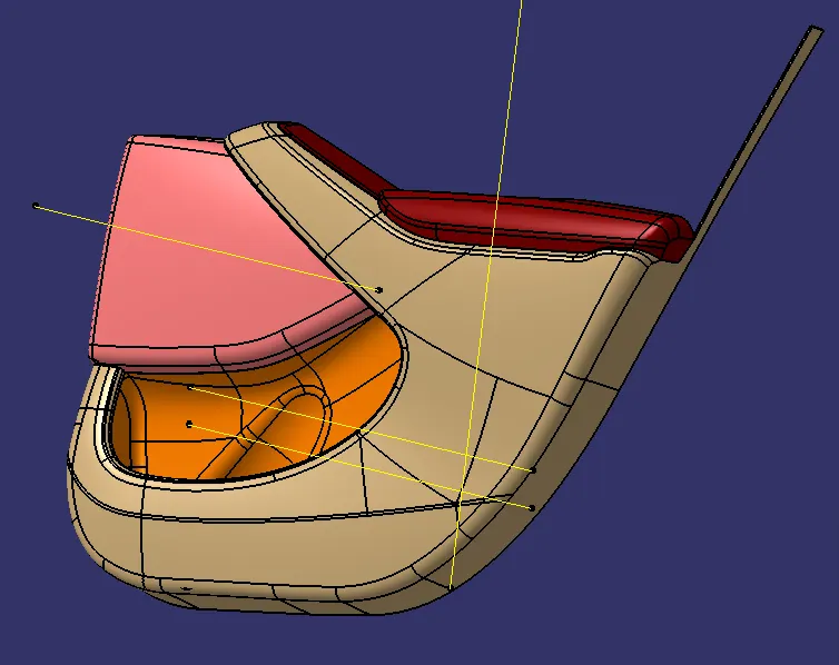
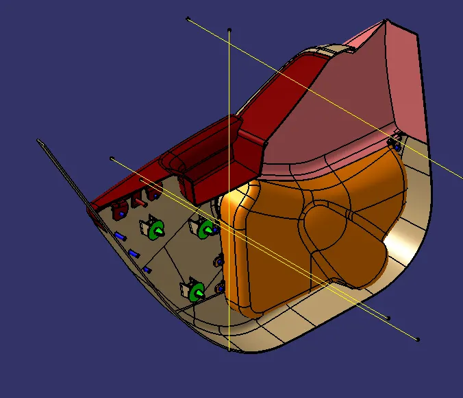
In this challenge the given A surface is made into a soid part by creating B and C side surfaceses respectively. the part given looks like the inner door trim of a car. all the parts are assembled with the help of b side features. Another input of push pin is given for assembling the part to the door sheet metal. Heat stakes are created and matted with parts as a whole assembly.
INPUTS GIVEN:
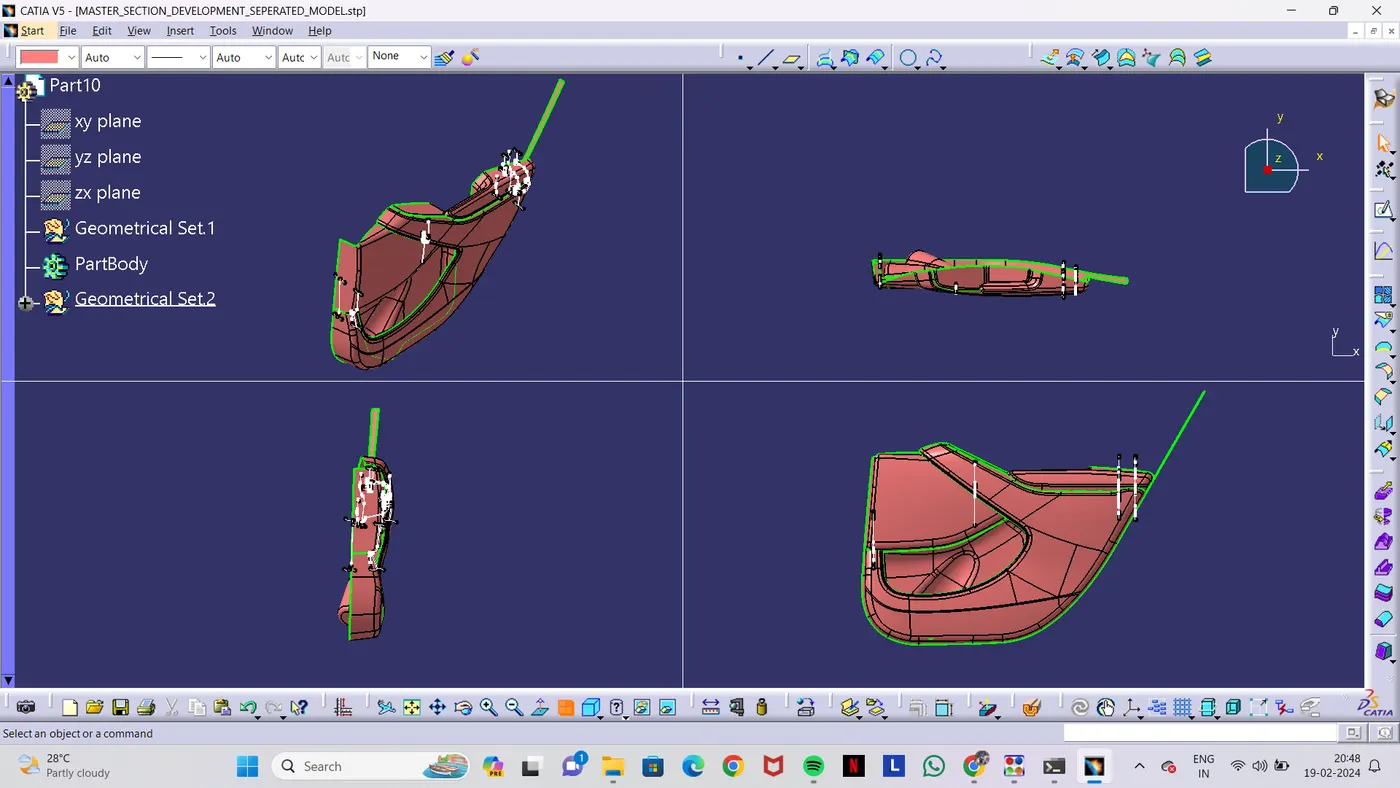
Arm Rest:
Class A surface Of Arm Rest:
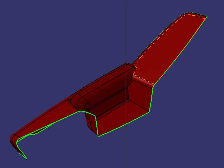
At first the given class A surface of arm rest is analysed for draft.
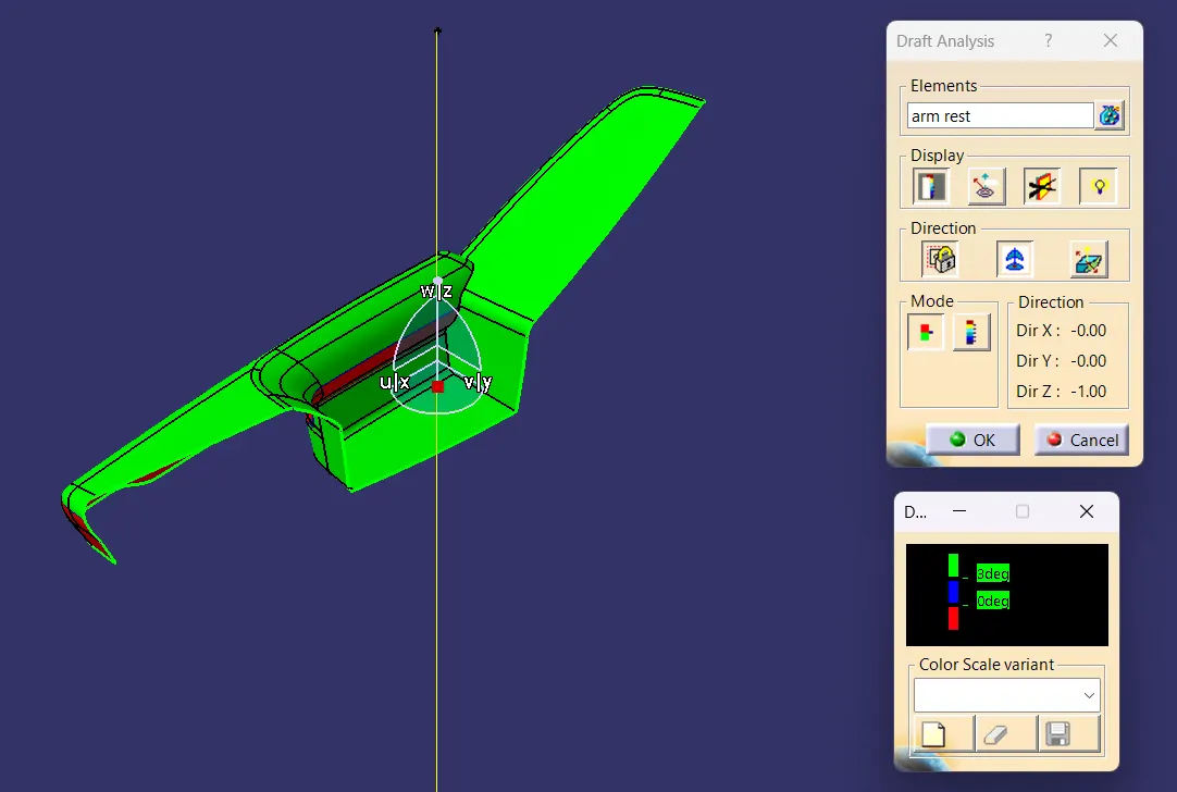
The arm rest is then converted into solid part of thickness 2.5mm. Class B and Class C surface are created and trimmed together. Flanges are created using the master section. there are two flange in the arm rest. The flanges are created with the input given by the mastersection.
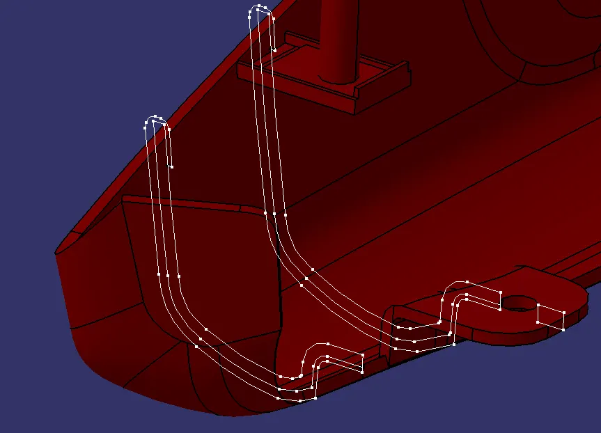
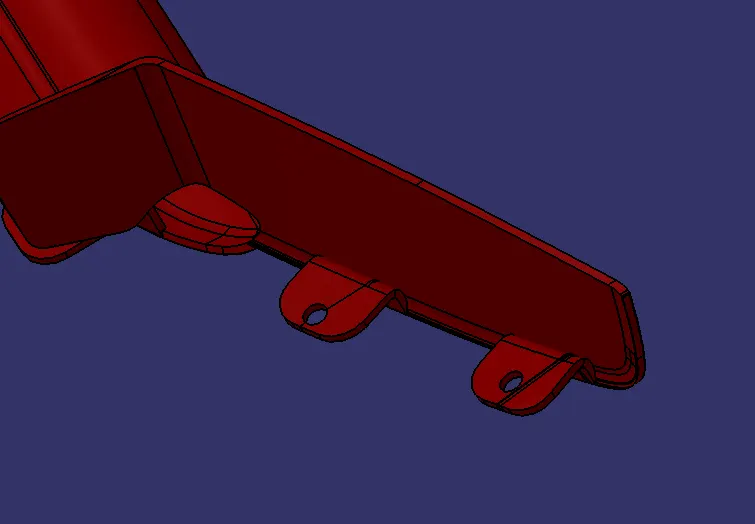
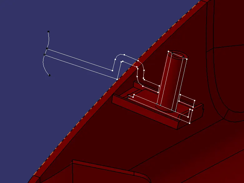
On studying the master sections given, it is found that there is a dog house on the arm rest. Using the master section the dog house is created.
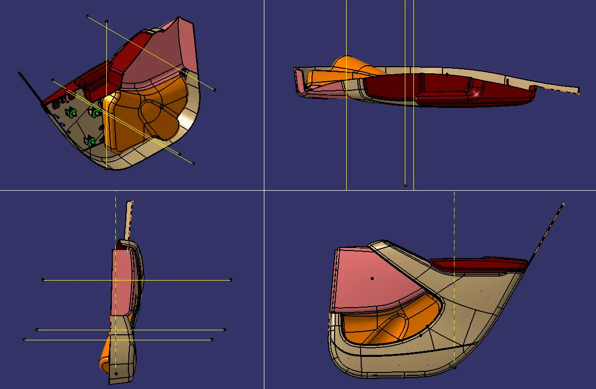
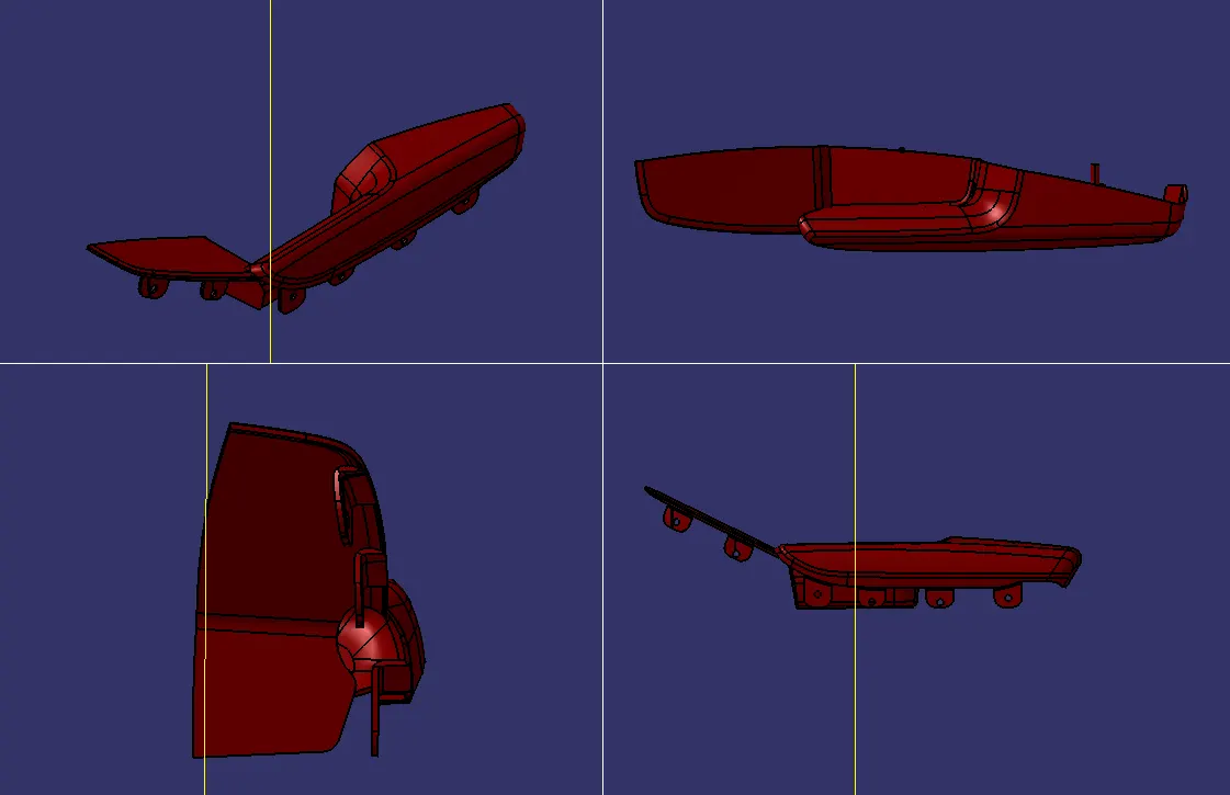
The isometric view, front view, side view and top view are shown below.
LOWER SUBSTRATE:
Class A surface and master sections were given as inputs.
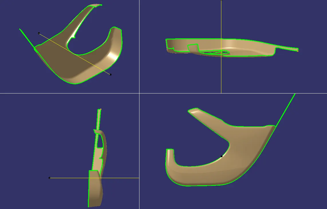
The given Class A surface of the lower substrate is analysied for draft for 3 degree
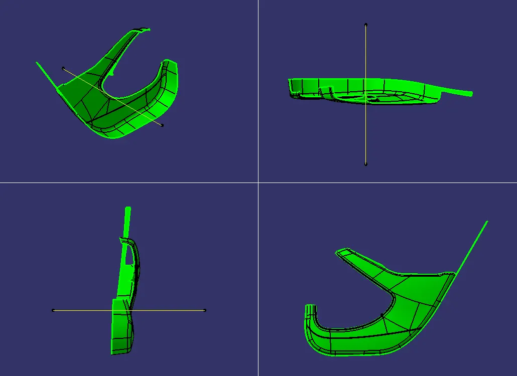
The class A surface after analysis is converted into a part for 2.5mm thickness. class B surface and class C surface is created and trimmed together to form a clossed surface. The clossed surface is then converted into a body using close surface command. By studying the master sections for the lower substrate we can tell that there are heat stakes located on the lower substrate for assembling the other parts with the lower substrate. So with the help of the mastersections heat stakes are craeted and located in various points. The heat stakes created are the union trimed with the lower substrate.
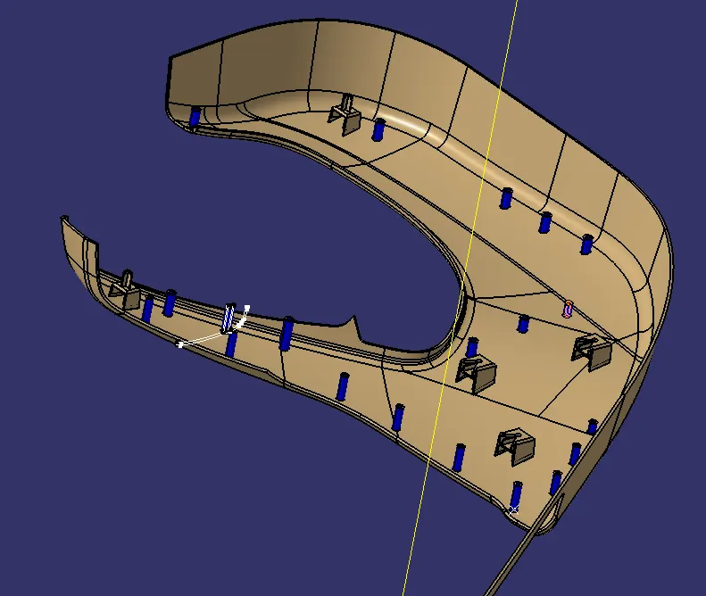
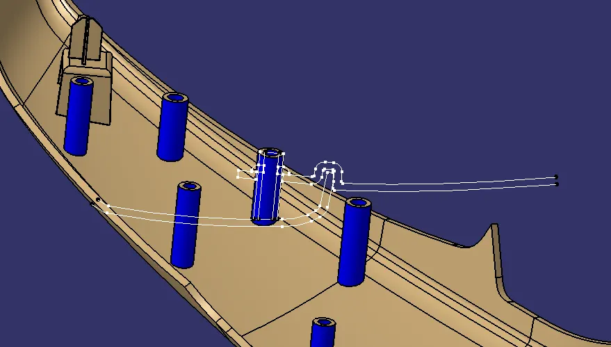
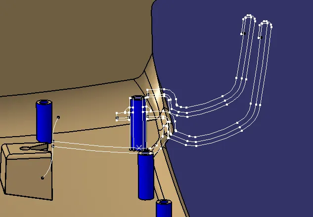
Dog house are also created so that the given push pin can be assembled and the whole set up can be attached to the sheet metal part of the door. Two four way locators created on top of dog houses to help proper assembly of parts. The length of the locators are longer than the heat stakes so, that the locators fix first and followed by heat stakes.
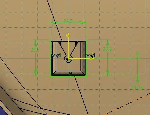
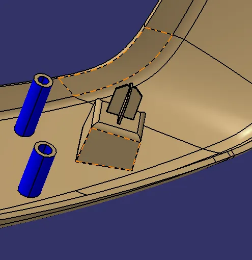
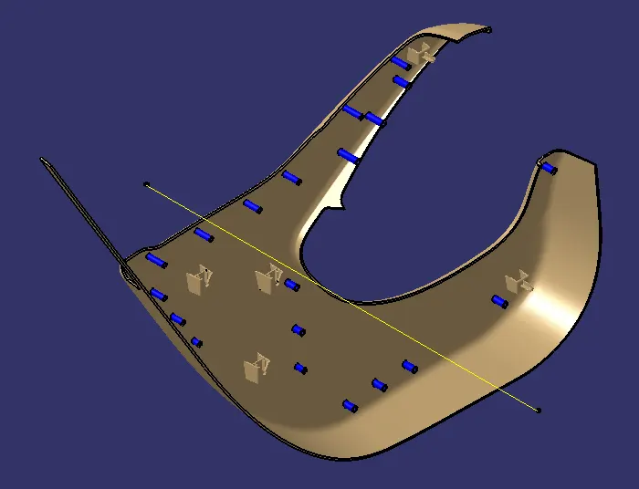
The dog house and the heat stakes are union trimmed to the lower substrate so that other parts can be assembled on lower substrate.
MAP POCKET:
Class A surface for the master section is given as input initially. The isometric, front, top and side view of the input is shown in figure bellow. Draft analysis is done to the class A surface.
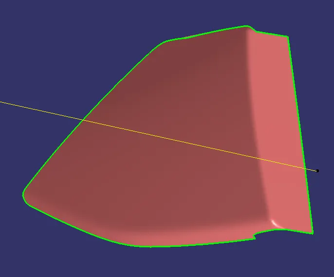
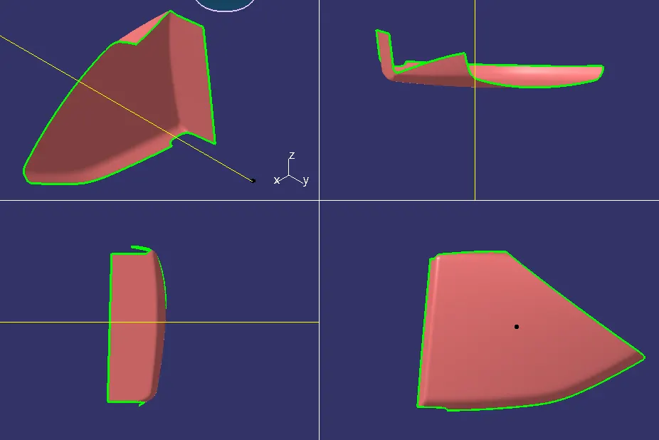
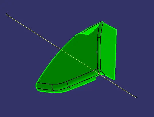
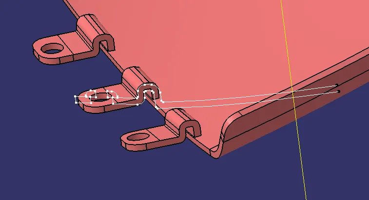
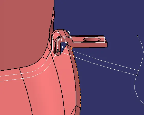
The class A surface is then converted into solid part by creating class B surface and Class C. The class B and Class C are trimmed together along with the class A surface thus, forming a clossed surface. The clossed surface is then converted into a solid part with the help of clossed surface command. From the master section given it is found that there is no heat staks located on the map pocket. The map pocket consists of flanges so that it is attached with other parts. Once the flange are created it is union trimmed with the map pocket to form a whole single body.
Bottle Holder:
Initially Class a surface is given as input for the bottler holder. The class A surface is analyised for draft
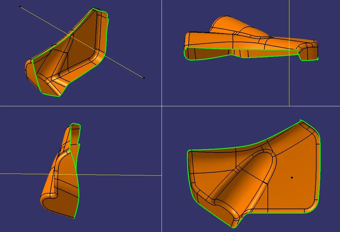
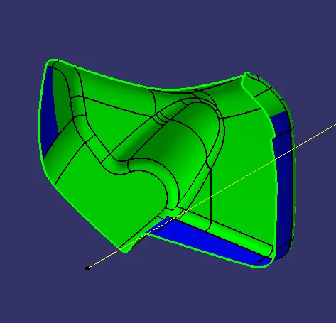
After the analysis the class A surface the Class B surface and Class C surface is created. The class B and Class C surfaces are trimmed together along with class A surface, thus forming a clossed surface. This clossed surface is then converted into a part by using close surface command. For the bottle holder after studying the inputs given it is found out that there are no inputs for creating a flange, hence flange are created with assumption of dimensions.
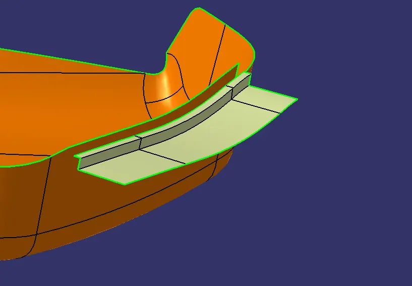
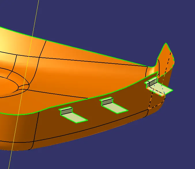
Here the surface for flange is created and then thickened by using thick surface command for 2.5mm thickness. This is done for all three flanges in the map pocket. once the flanges are created the flanges are union trimmed with the bottle holder body to form a whole single body.
ASSEMBLY OF PARTS:
Once the given A surface is converted into a part body, the induvidual parts has to assembled together by arresting the required degree of freedoms. To do so, a reference point is created and fixed a the origin point, so that it is constrained in all degree of freedom. Then the required axis and reference point that are required for constrianing the part together are published induvidually in the respective part workbench. The published inputs are then used while the time of assembling the parts together. Once all parts are attached together push pin is also assembled to it as shown below.