Week 12- Final project
OBJECTIVE:
The objective of this project is to create and design a CAD model of a Side Door Trim Panel component from the given Class-A surface using CATIA V5
Importance of plastics in the automotive industry:
Plastics play an important role in the automotive industry as the market in recent times demands lightweight, affordable, fuel-efficient, safe, comfortable, and high material performance automobiles. Plastics have been used in cars since the early 1950s, but it’s the latest innovations that are changing the industry for the better. Engineered polymers and plastics are continuing to replace aluminum and other metals in automobiles, with the average car interior now being made up of over 50% plastics. Over 1,000 different car parts are now made of plastics, and these plastics can be moulded together to replace the need for multiple parts, keeping manufacturing efficient and weight down.
Types of plastics used in a car:
- Polypropylene
- Polycarbonate
- Acrylonitrile Butadiene Styrene
DESIGN PLAN :
- Class A surface extraction.
- Separate and sort the single Class A surface into respective components using Geometrical sets.
- Necessary Main/Side Tooling axis creation.
- Draft Analysis on Class A surface component-wise.
- Class B surface obtained after offset and extrapolation in the appropriate direction.
- Class C surface created using Tooling axis as reference draft direction.
- Class A, B, and C are trimmed together to form the finished surface of different components.
- A closed surface is converted into a solid followed by a draft analysis of the solid component.
- The various attachment features were created on the Class B surface while following the design guidelines.
DOOR TRIM PANEL CONSISTS OF FOLLOWING COMPONENTS:
- ARM REST
- LOWER SUBSTRATE
- TOP MAP POCKET
- BOTTLE HOLDER
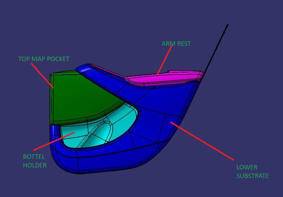
ARM REST:
CLASS A CREATION:
In Automotive Industry There Will Be a Dedicated Team Who Will Perform The Aesthetic Designing Of Various Components Including The Whole Vehicle. They Will Create Various Concept Sketches After Ideation. After That, They Will also create a Class A Surface Of The Product. This Class A Surface Is Then Passed OverTo The NPD CAD Team. They Will Initially Inspect The Class A Surface In Order To Check If The Design Is Manufacturable Or If It Is Following The Engineering Principles. If There Are Any Issues About The Design, They Will Contact The Product Design Team And Will Ask To Modify The Class A Surface In Order To Solve The Problem.
Initially, we need to check the Draft Analysis of every part given to us, to Check the Draft Analysis we need to create a Tooling Axis for every part.
Class A Surface image mention below
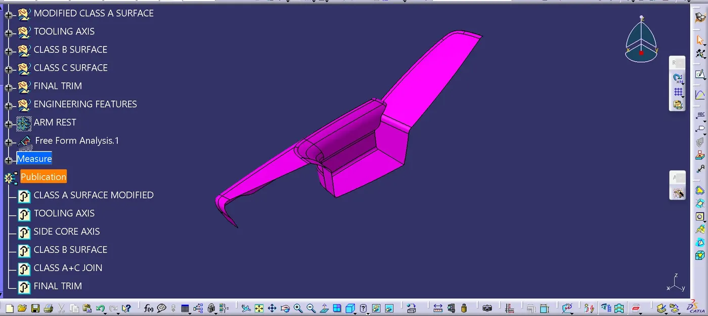
TOOLIN AXIS :
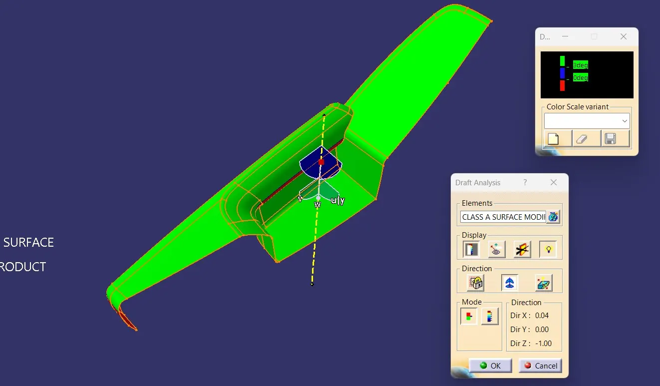
The Tooling Direction is the direction that the mold pulls apart. The mold is built into two separate pieces. You have a Cavity side and you have the Core side. The Core pulls apart from the Cavity and that's the Dyeline or the Tooling Direction.
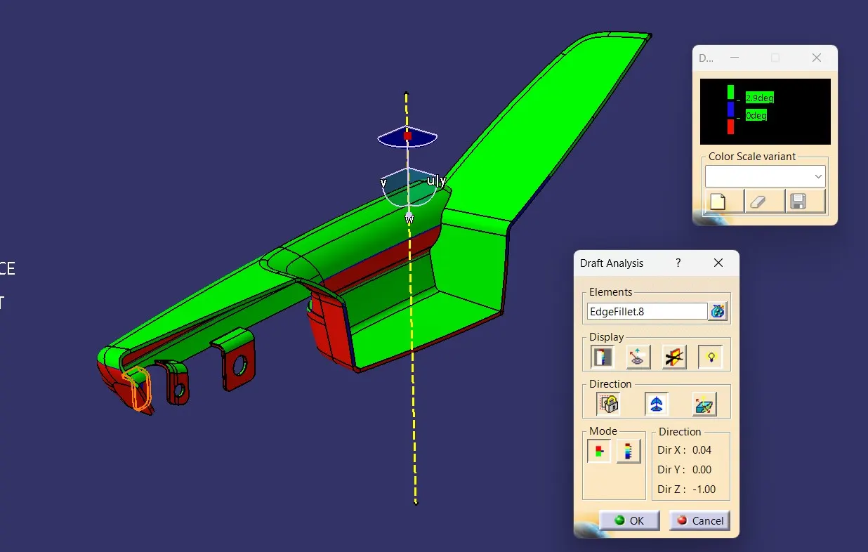
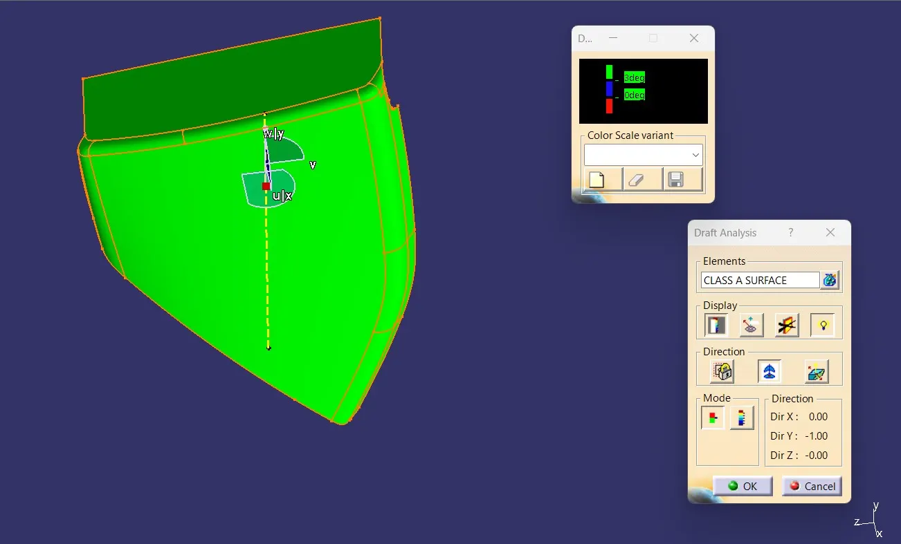
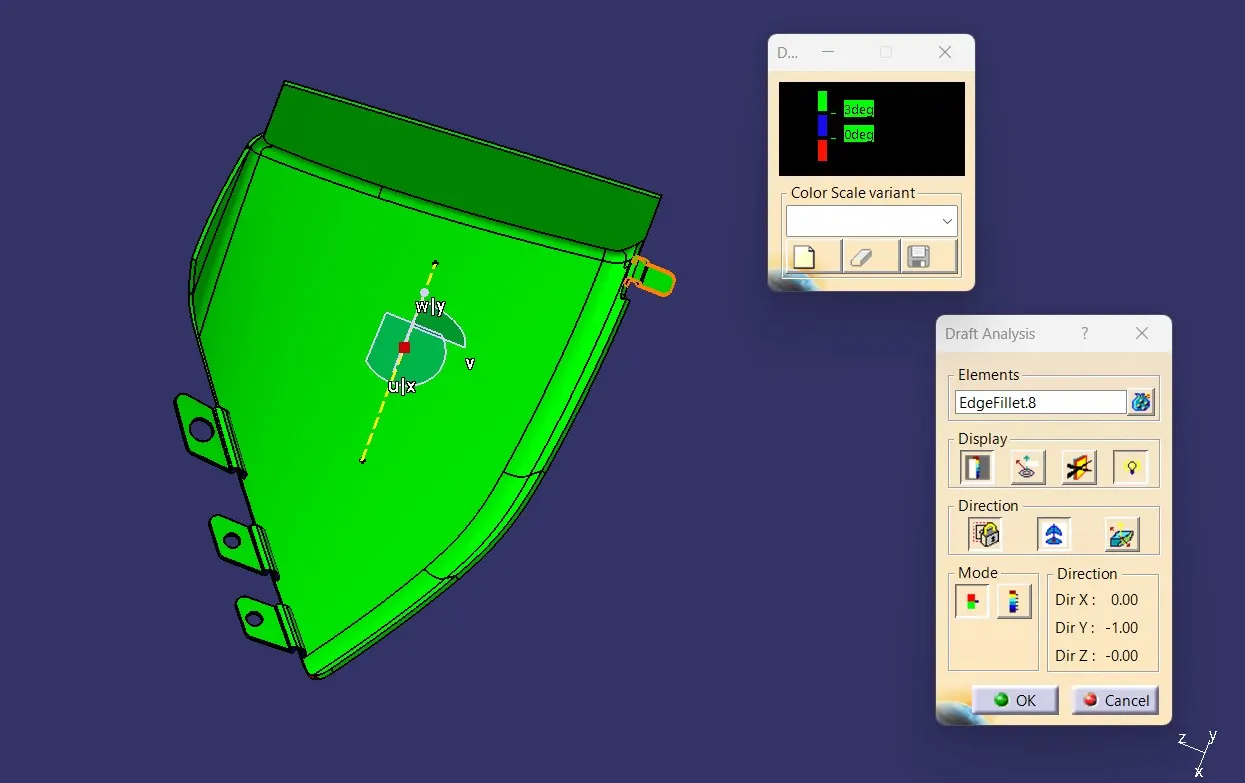
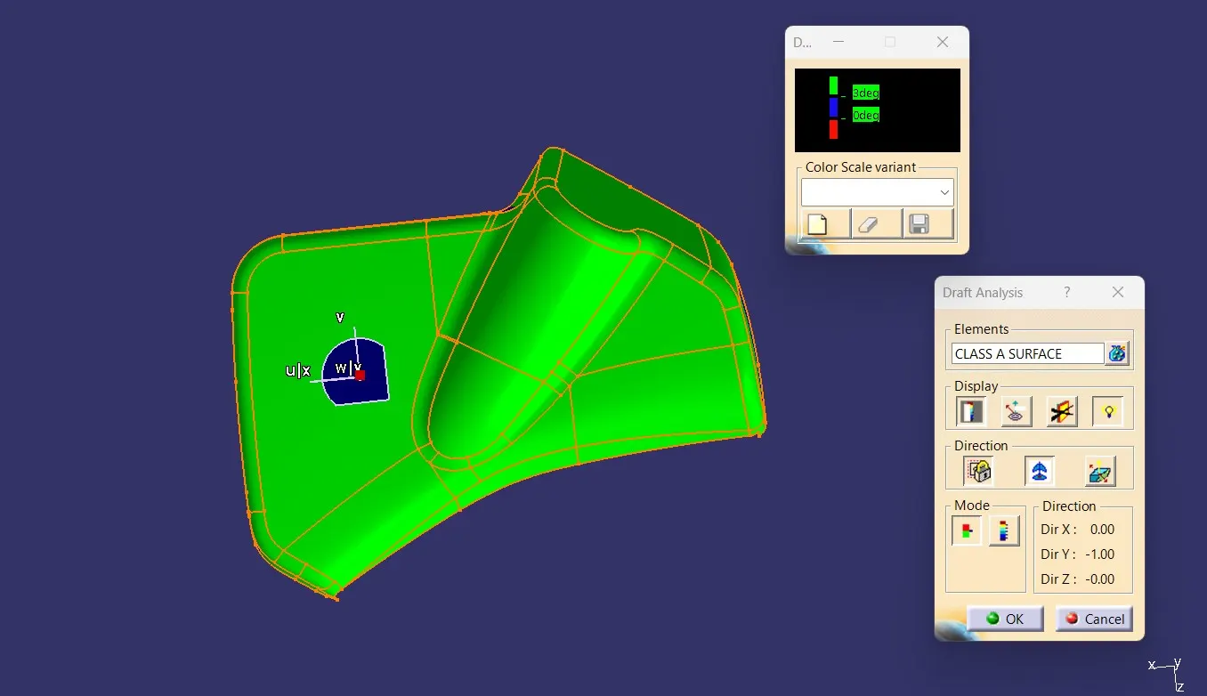
We've provided a minimum draft angle value of 3 degrees which should be cleared by class A in every direction and the green color indicates that the angle is above 3 degrees in all directions.
Draft analysis of Arm rest image mention below
CLASS B CREATION:
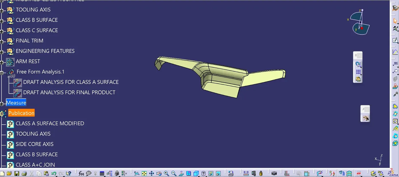
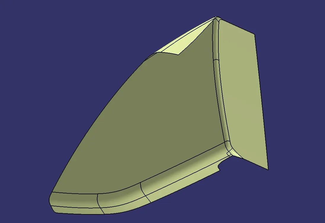
Next, we proceed to Class B surface creation. Class B refers to the non-aesthetic surface that is not visible to the eye when looked upon from outside but rather connected to the other parts of a car using attachment features that lie on this surface.
For obtaining a class B surface, we simply offset the class A surface by the required distance(thickness of the component) in the correct direction.
Class B Surface image mention below
CLASS C CREATION:
After this, we create a class C surface that forms the thickness/cross-section of the solid part. For class C surface, we use a combination of commands such as sweep, multisection surface, extract and extrapolate to obtain the surface and then join them together to form a full surface.
By Using the Sweep with reference to the Surface at an angle of 87deg we get the C surface from thereafter creating the sweeps around the bottle holder trim the unwanted surfaces & add the created c surface to Class A.
Class C Surface image mention below:
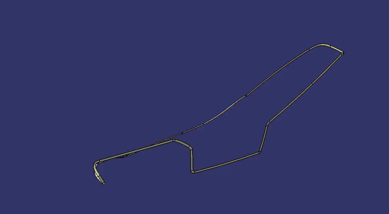
CLASS A+C SURFACE JOIN:
And then join the class A and C surface together image mention below
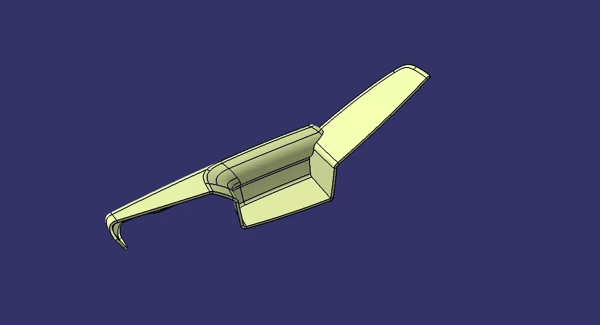
And then trim the class A and C surface join with the Class B surface image mention below
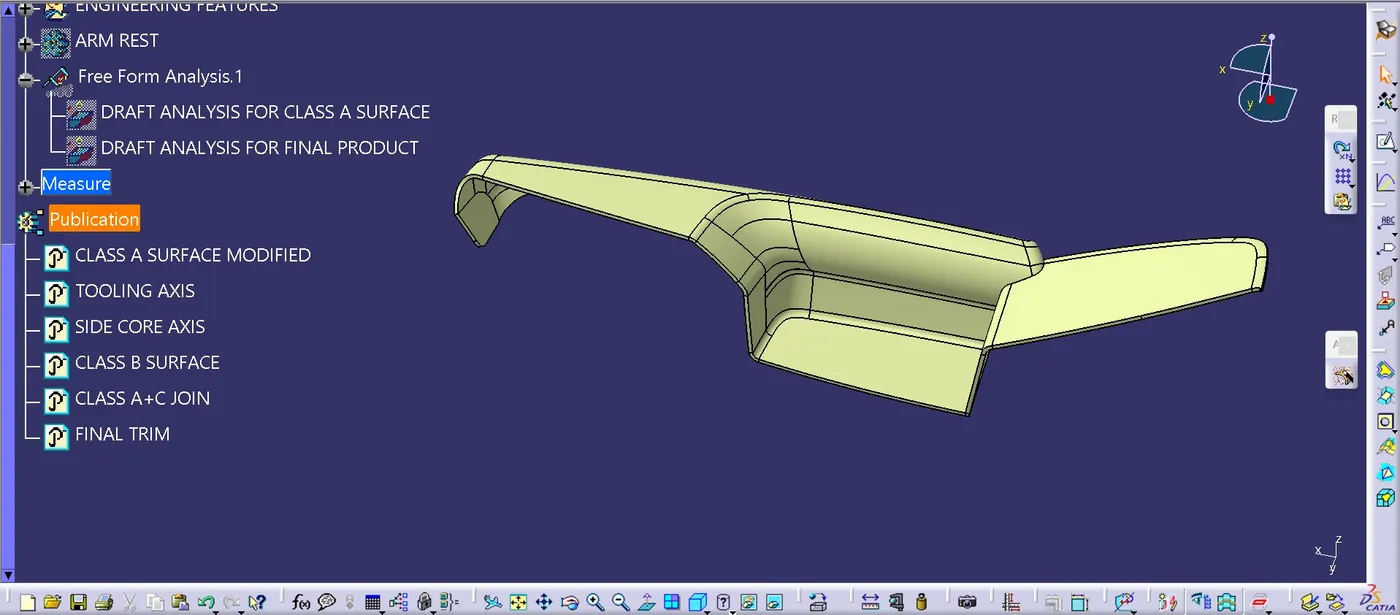
And then finally made the closed body from closed surface image mention below
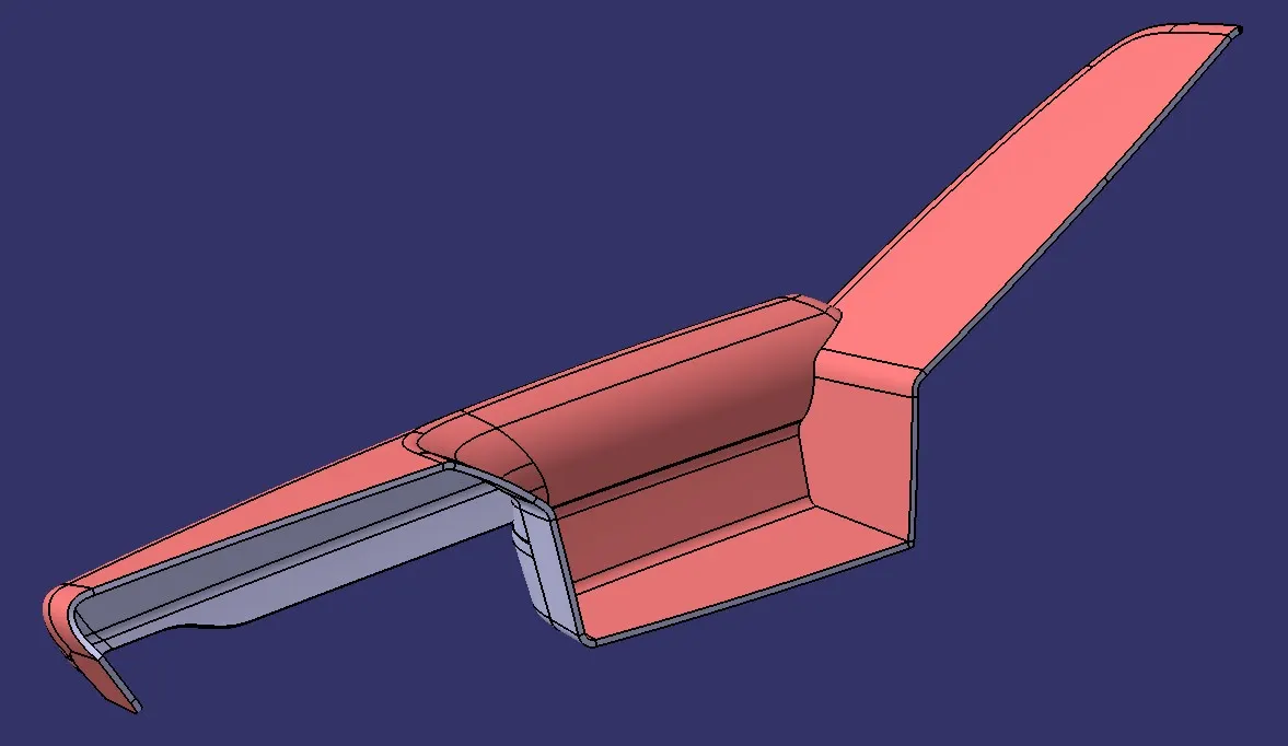
And create the B-side features with the the help of the master section given as input following image is mention below
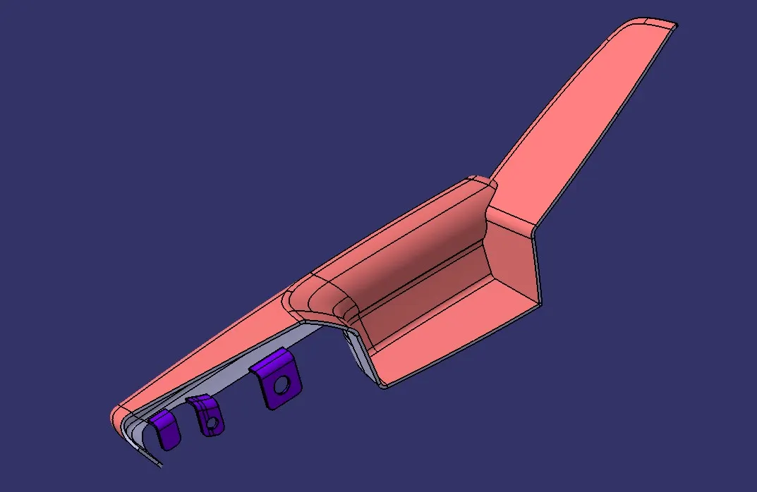
Above mention image show that the three flanges are created according to the master section the three flanges are considere as the B-SIDE FEATURES let see about the B- side features.
B SIDE FEATURES/ATTACHMENT FEATURES:
Attachment features on the plastics have many uses like improved strength of the component, attach one component with another, locate a component for mold to move it(to pour the molten plastic), arrest motion of one component concerning another, and attaching the finished plastic to the metal BiW(Body In White).
USES OF B SIDE FEATURES:
- Simplification of machinery
- Reduced cost of machinery
- Multiple fastening points
- Allows higher density of welds compared to hot air cold form or ultrasonic welding
CLOSED BODY DRAFT ANALYSIS:
Insert > Analysis > Feature Draft Analysis
- Define the Draft direction using the "Compass" option.
- Drag the Axis system representation close to the model and align it along the tooling axis.
- "Lock" the Draft direction.
- Set the Colour scale
- Place the Analysis Tool (Arrow Icon) anywhere on the model and review the colors on the feature.
- If any feature (especially C surface) is showing Blue/Red then choose the same option again (It will switch to Analysis under Running point) and place it on the respective feature to review the deviation of the sweep angle from the Tooling Axis.
Draft analysis of closed body arm rest image shown in below
And then measure the weight of the Arm rest image shown in below
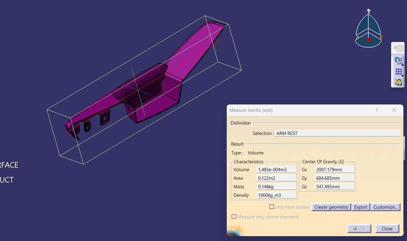
So, weight of the arm rest is 0.148kg
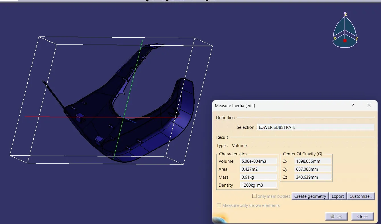
LOWER SUBSTRATE:
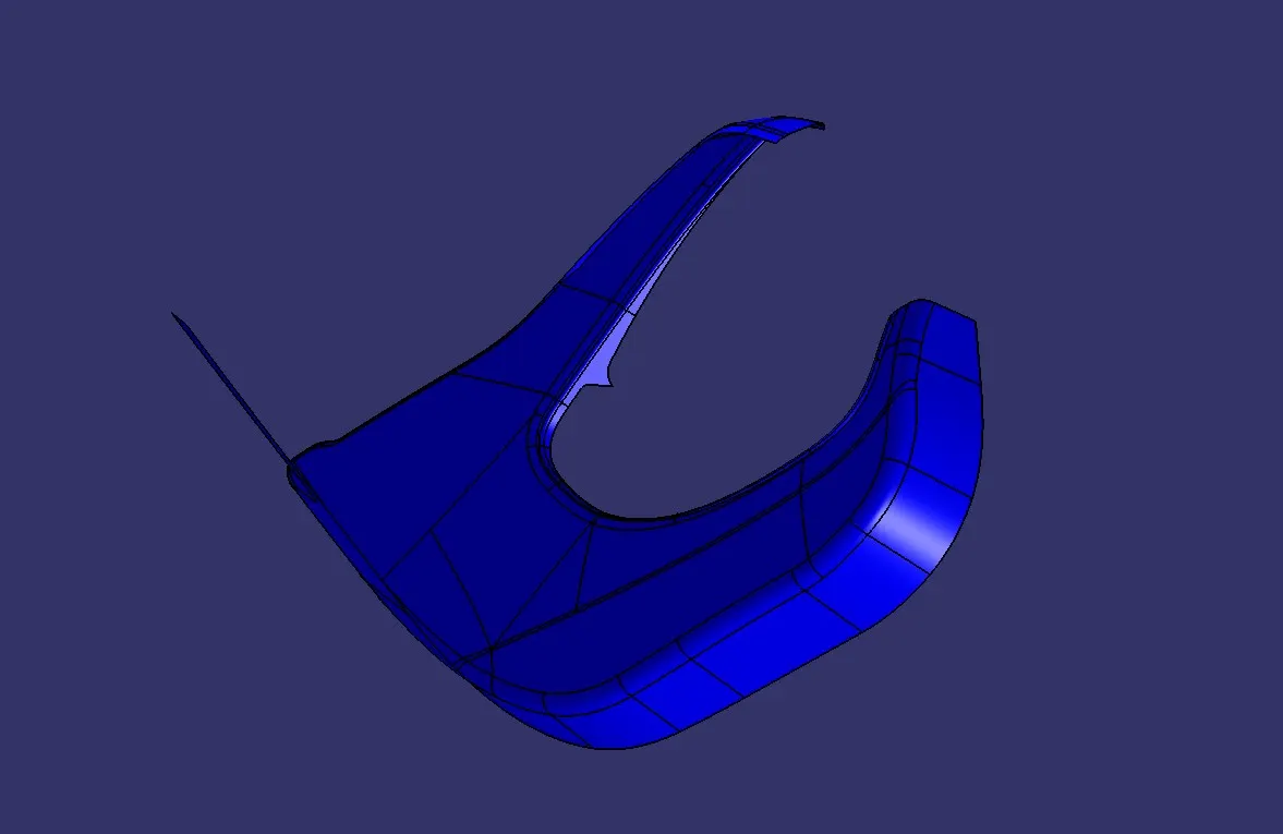
CLASS A SURFACE AS INPUT IMAGE MENTION BELOW
DRAFT ANALYSIS CLASS A SURFACE (LOWER SUBSTRATE) WITH TOOLING AXIS
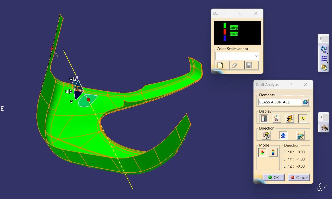
NEXT CLASS B SURFACE IS CREATED FROM CLASS A SURFACE OFFSET TO 2.5mm ACCORDING TO THE MASTER SECTION.
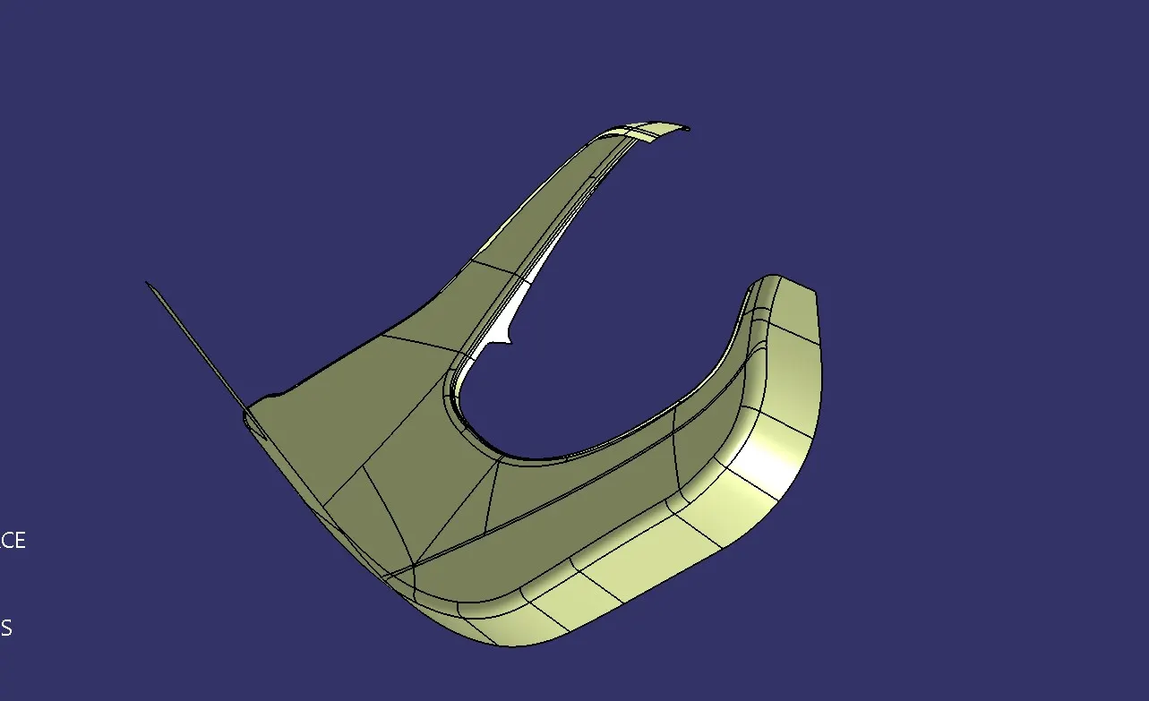
CLASS C SURFACE IMAGE SHOWN BELOW
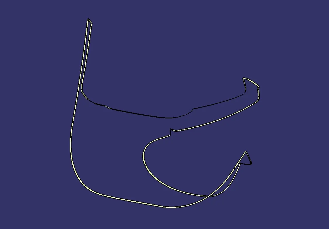
And join the class A and C surface and then trim with the class B surface
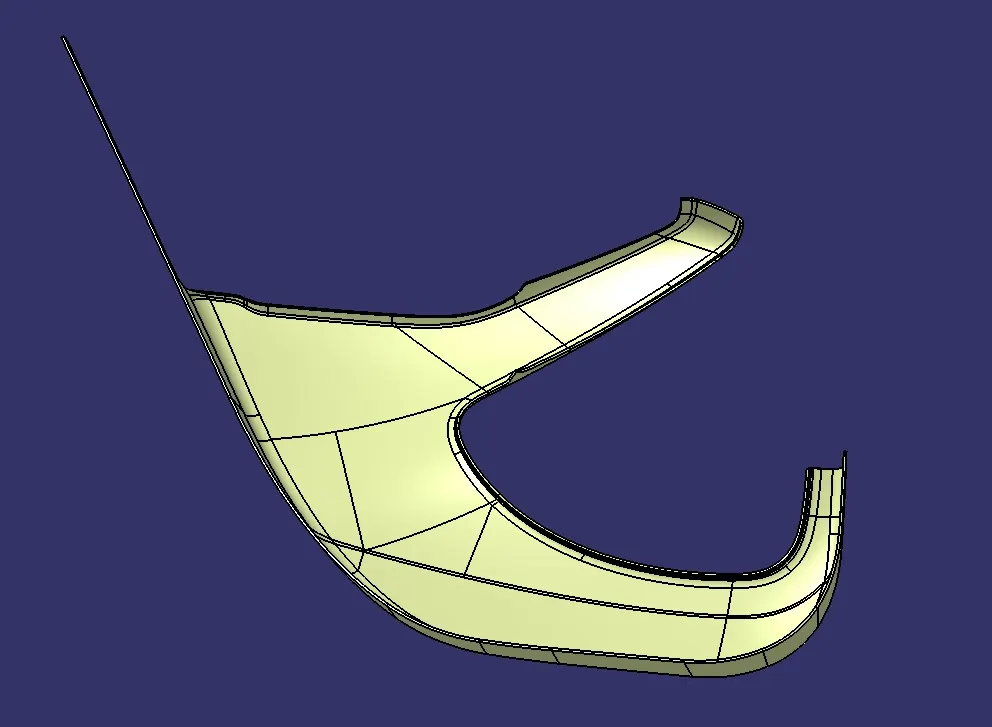
Then make into a solid body shown in below
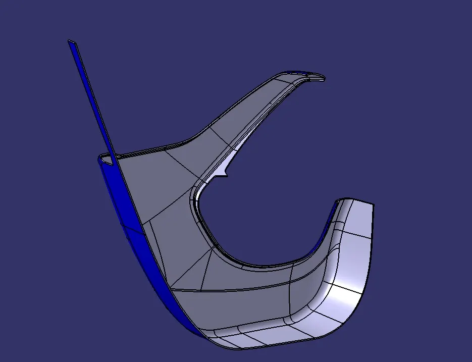
Make B SIDE FEATURES Like Dog house,Heat Stakes,Locator and so on... some of them have a master section and for the rest we have to find our own fixing and attachment strategy
LOCATORS:
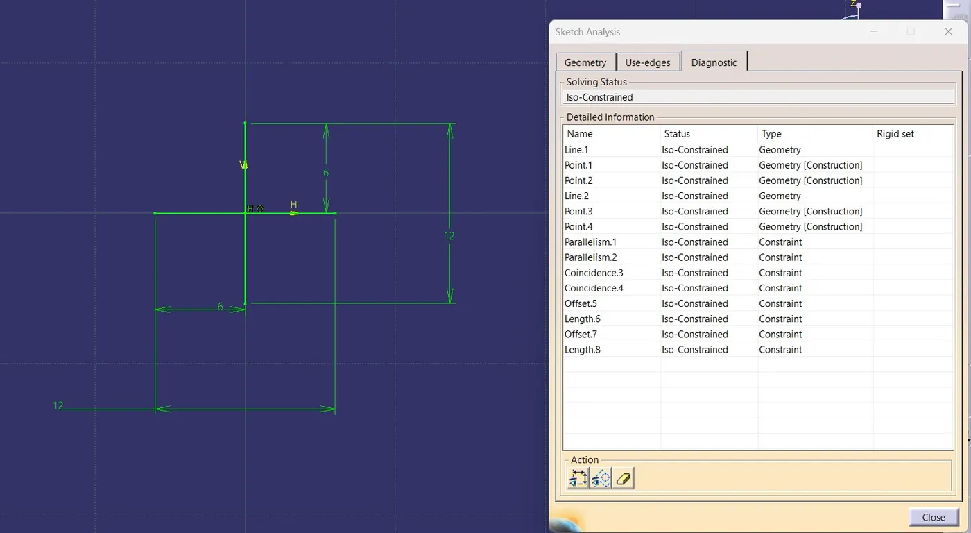
Locator is another attachment feature that is vital to any component obtained through the molding process as it acts as a guide for the mold to move into position and there is no mismatch between the two(top and bottom) half of the mold. There are two classifications of locators, 2-way and 4-way. A simple method to remember the difference between them is to consider the 3 axes of translational motion, and the 6 corresponding directions or Degrees of Freedom.A 2-way locator restricts motion along 1 axis (or 2 degrees of Freedom), like a round pin in a slot. Likewise, a 4-way locator restricts 4 degrees of freedom along 2 axes. A round locating pin located concentrically in a hole is a common application of a 4-way locator and helps to further secure the piece. To sufficiently locate a part, a minimum of one of each type of locator is required to prevent excess motion of the workpiece, and more locating components may be used as needed.
LOCATOR SKTECH IMAGE MENTION BELOW
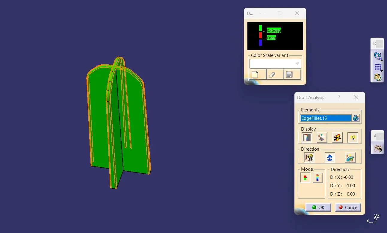
DRAFT ANALYSIS FOR LOCATOR IMAGE MENTION BELOW
DOG HOUSE:
Dog house is an engineering feature used in the plastic trim design. The primary function of a dog house is to avoid sink marks on the class A surface which may occur due to features such as a locator or rib on the backside of Class. So the best possible solution is to increase the height and decrease the cross-sectional thickness of the ‘legs’ by using a dog house. We can also use them for solving the neccessity of large length features such as Heat Stakes And Locators which may require large lengths sometimes.
DRAFT ANALYSIS FOR DOG HOUSE MENTION BELOW
We Draft the dog house for 1.5 degree so we give draft angle of 1.45 and then we got the clearance for outer side of the dog house
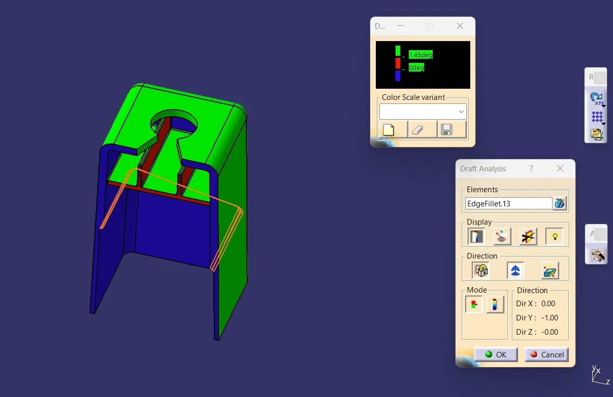
In the below image we draft the dog house inside rib with 0.5 degree so we give the draft angle as 0.45 degree
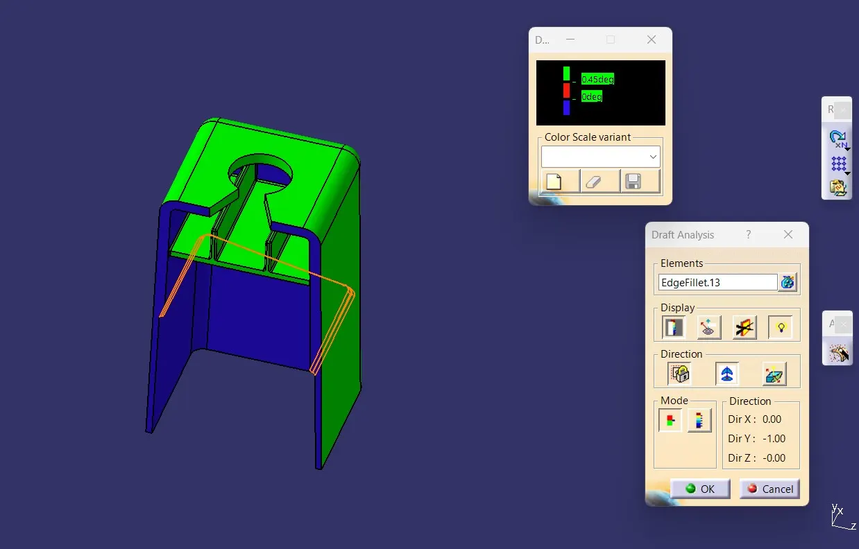
We Design the Dog house as per the design rules and guidelines
HEAT STAKES:
The process of heat staking also known as thermoplastic staking is the process of joining two dissimilar materials together. In heat staking, we use local heating and cooling to raise the temperature of plastic components and allow plastic reforming to be carried out. This reforming process attaches one plastic component with another as the plastic cools and solidifies.
DRAFT ANALYSIS FOR HEAT STAKES IMAGE WAS MENTION BELOW
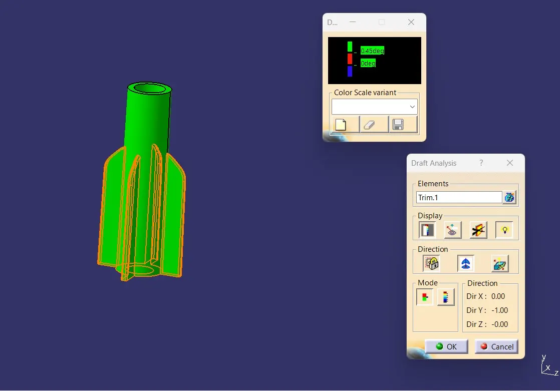
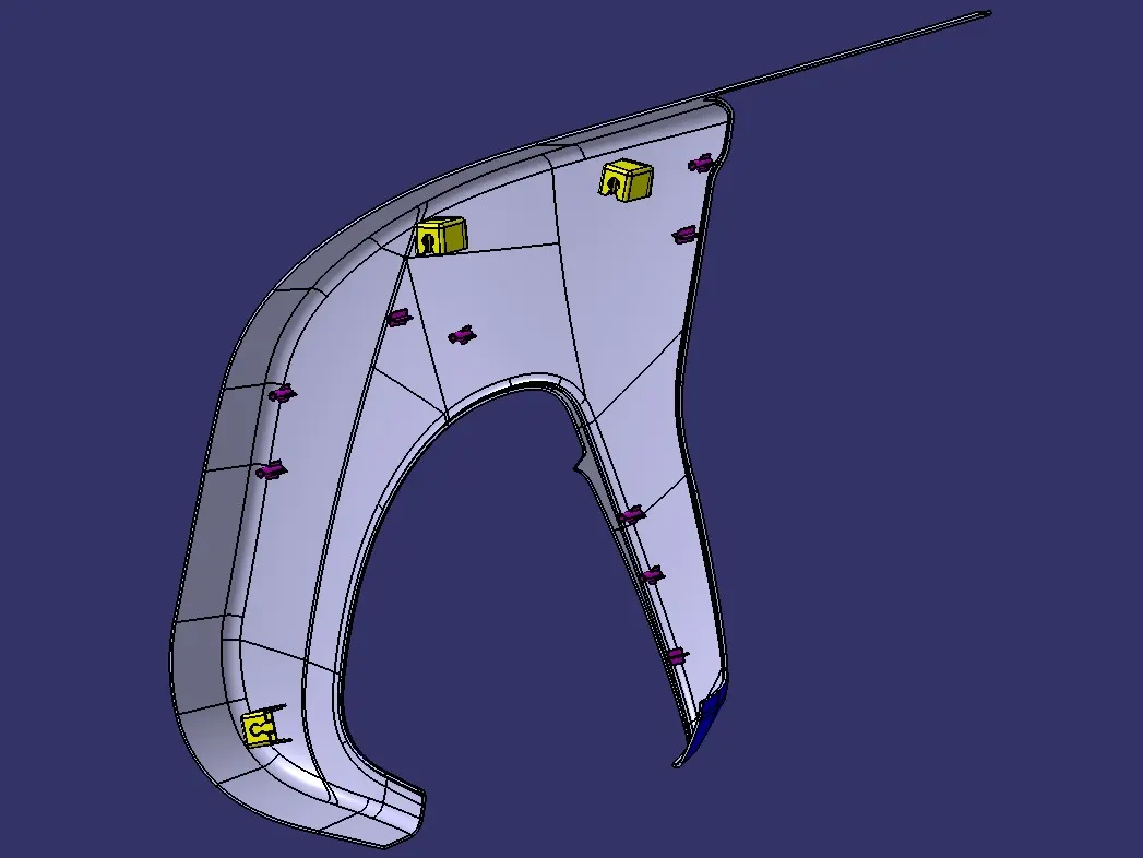
Most of the B side features are persent in the Lower Substrate
Final product of the Lower substrate image mention below
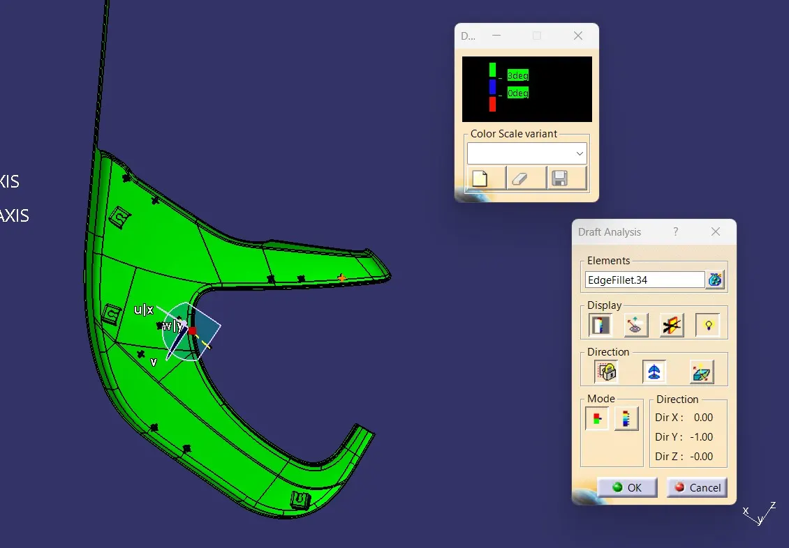
DRAFT ANALYSIS OF THE FINAL PRODUCT OF LOWER SUBSTRATE
WEIGHT OF THE LOWER SUBSTRATE IMAGE MENTION BELOW
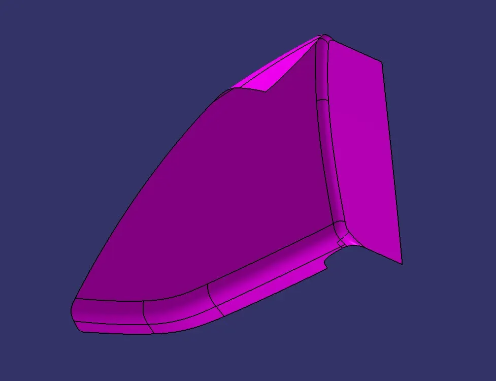
TOP MAP POCKET:
CLASS A SURFACE IMAGE MENTION BELOW
DRAFT ANALYSIS OF TOP MAP POCKET WITH TOOLING AXIS IMAGE MENTION BELOW
AFTER THE DRAFT ANALYSIS TO CREATE THE CLASS B SURFACE BY OFFSET THE CLASS A SURFACE ABOUT 2.5mm WITH THE REFERENCE MASTER SECTION IMAGE MENTION BELOW
NEXT TO CREATE THE CLASS C SURFACE IMAGE MENTION BELOW
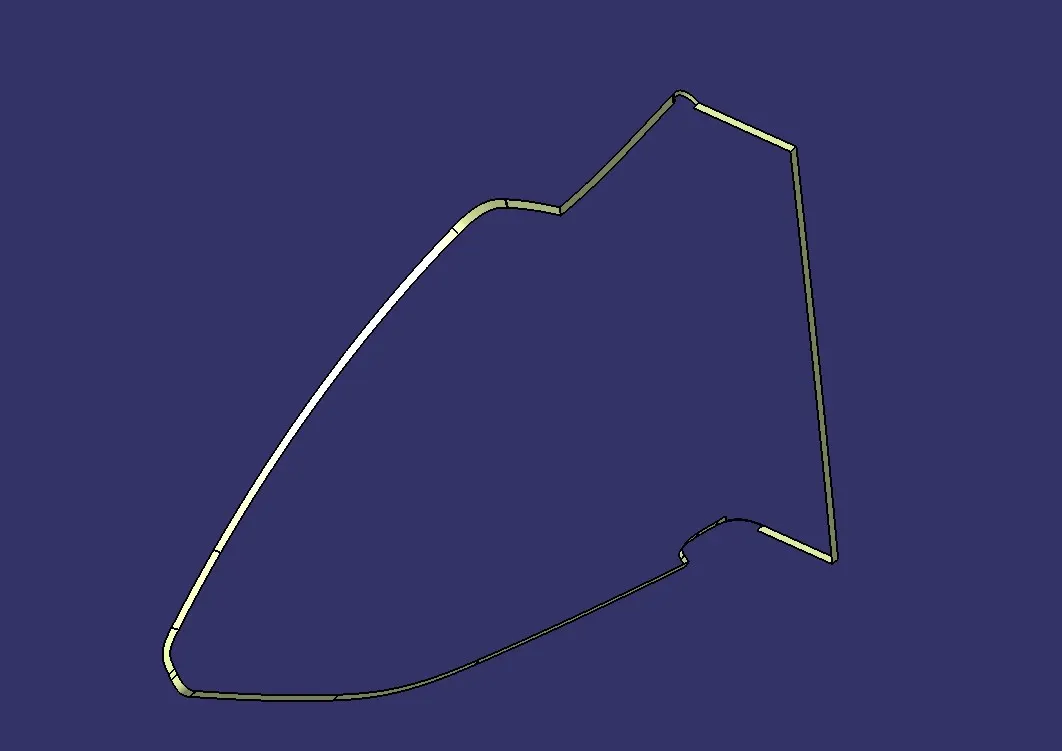
AND JOIN THE CLASS A SURFACE WITH THE CLASS C SURAFCE IMAGE MENTION BELOW
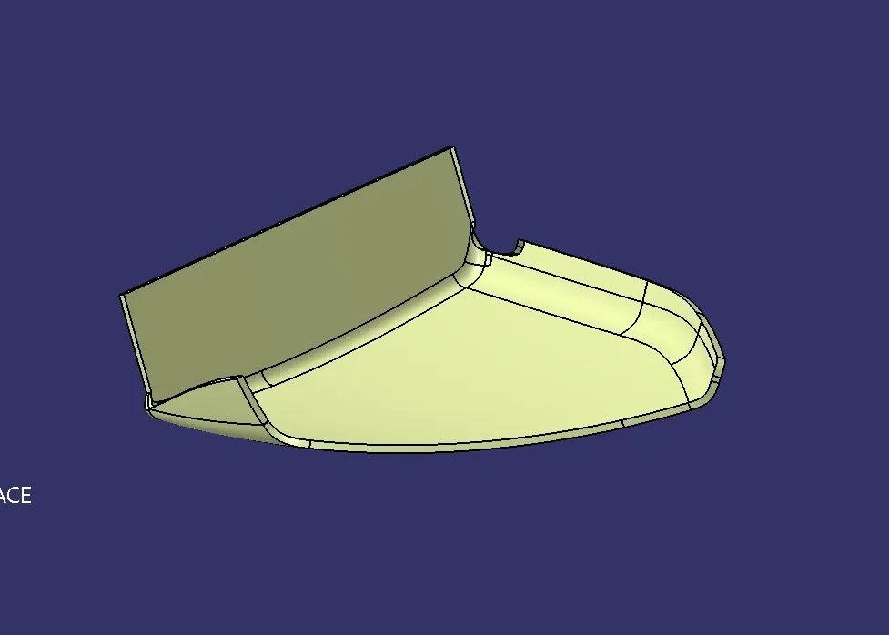
AND TRIM THE CLASS A AND C SURFACE JOIN WITH THE CLASS B SURFACE TO GET THE CLOSED SURFACE IMAGE MENTION BELOW
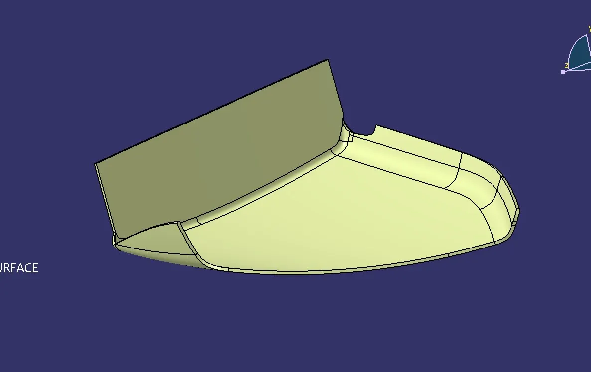
LET MAKE INTO THE SOLID CLOSED BODY IMAGE MENTION BELOW
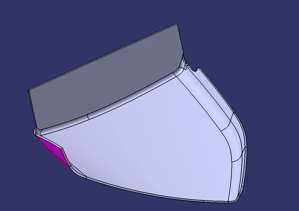
AND MAKE THE B SIDE FEATURES LIKE FLANGES USING THE MASTER SECTION IMAGE MENTION BELOW
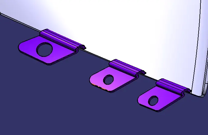
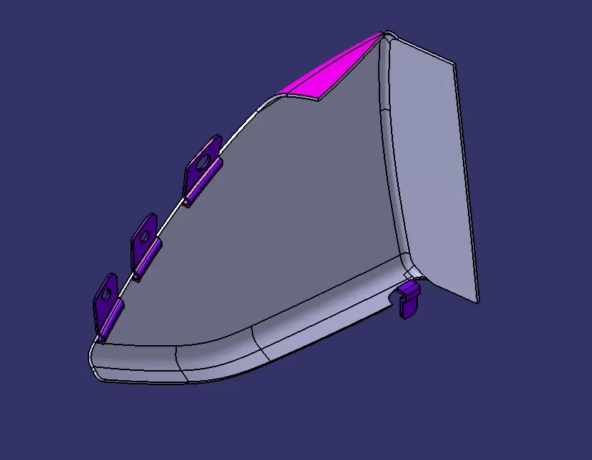
AFTER CREATING THE FLANGES IT DOES MATCH WITH THE HEAT STAKES PLACED IN THE LOWER SUBSTRATE AND THE FINAL PRODUCT IMAGE MENTION BELOW
DRAFT ANALYSIS FOR THE FINAL PRODUCT WAS MENTION BELOW
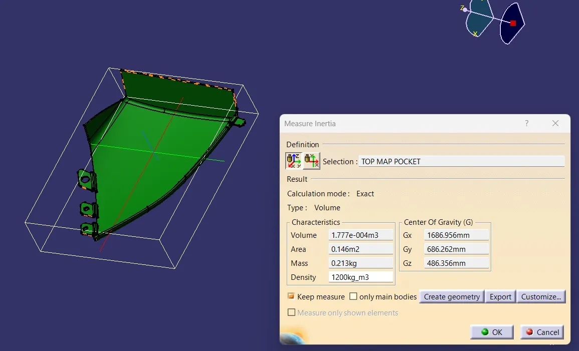
WEIGHT OF THE TOP MAP POCKET IMAGE MENTION BELOW
BOTTLE HOLDER:
CLASS A SURFACE OF BOTTLE HOLDER IMAGE MENTION BELOW
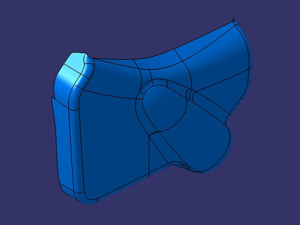
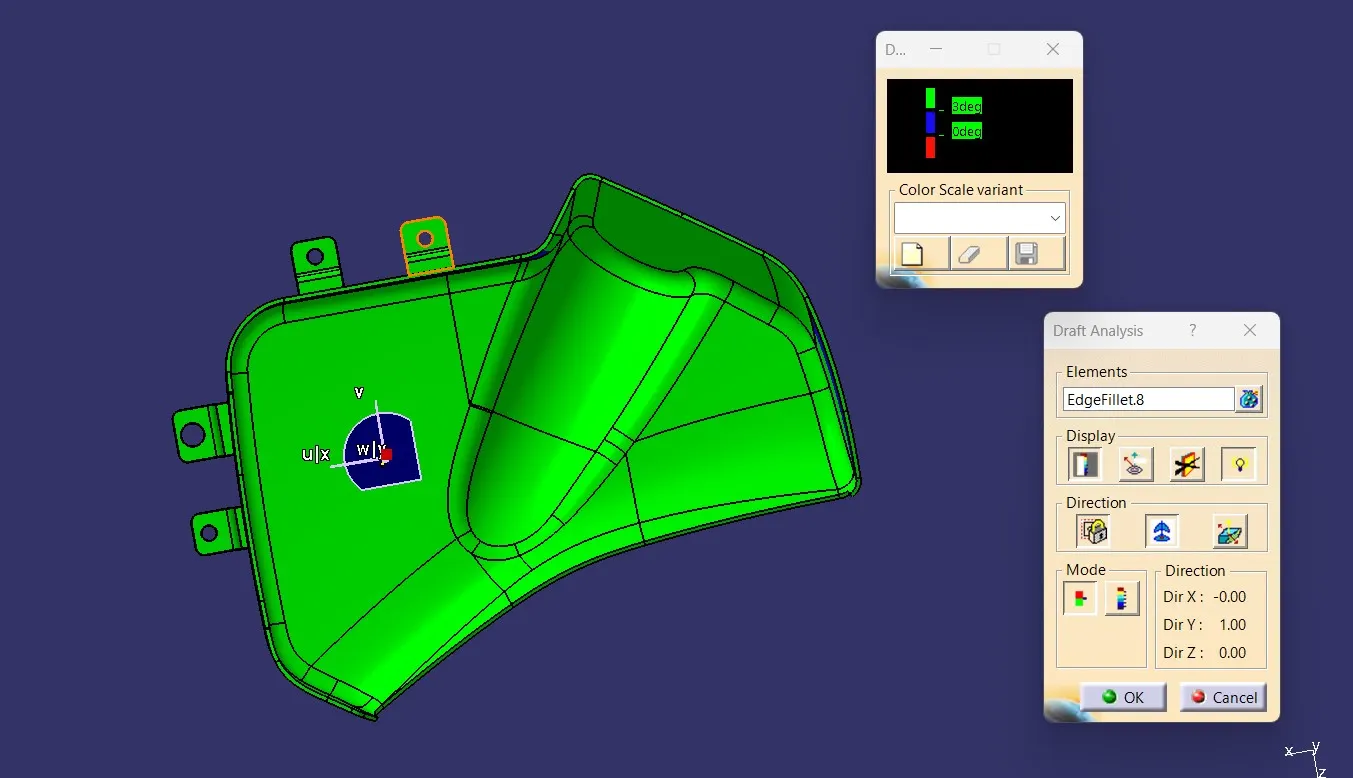
DRAFT ANALYSIS OF BOTTEL HOLDER WITH TOOLING AXIS IMAGE MENTION BELOW
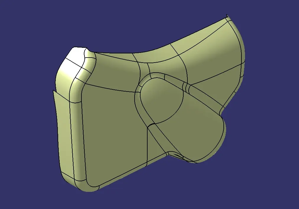
AFTER THE DRAFT ANALYSIS TO CREATE THE CLASS B SURFACE BY OFFSET THE CLASS A SURFACE ABOUT 2.5mm WITH THE REFERENCE MASTER SECTION IMAGE MENTION BELOW
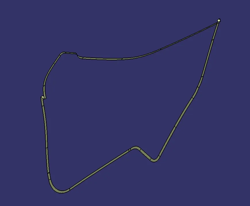
NEXT TO CREATE THE CLASS C SURFACE IMAGE MENTION BELOW
AND JOIN THE CLASS A SURFACE WITH THE CLASS C SURAFCE IMAGE MENTION BELOW
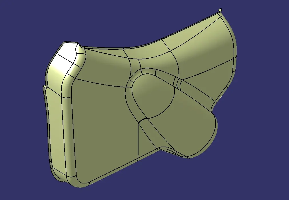
AND TRIM THE CLASS A AND C SURFACE JOIN WITH THE CLASS B SURFACE TO GET THE CLOSED SURFACE IMAGE MENTION BELOW
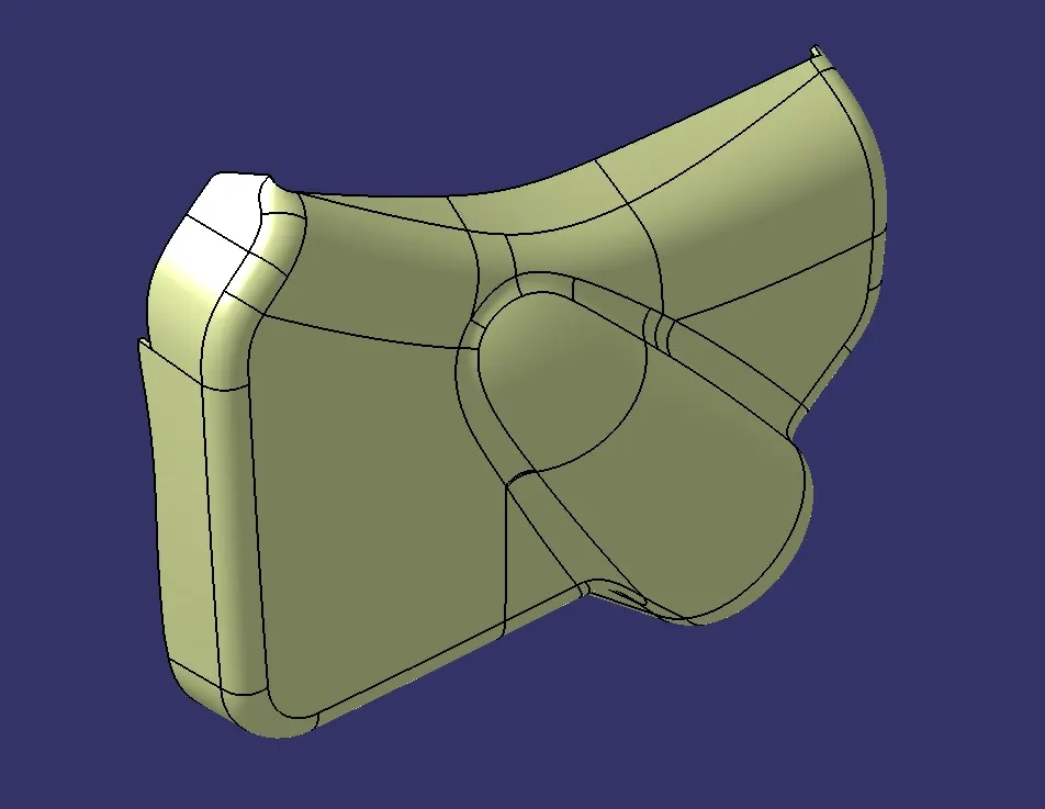
LET MAKE INTO THE SOLID CLOSED BODY IMAGE MENTION BELOW
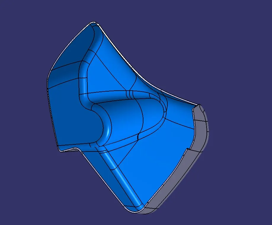
AND MAKE THE B SIDE FEATURES LIKE FLANGES USING THE MASTER SECTION IMAGE MENTION BELOW
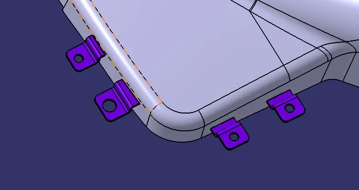
AFTER CREATING THE FLANGES IT DOES MATCH WITH THE HEAT STAKES PLACED IN THE LOWER SUBSTRATE AND THE FINAL PRODUCT IMAGE MENTION BELOW
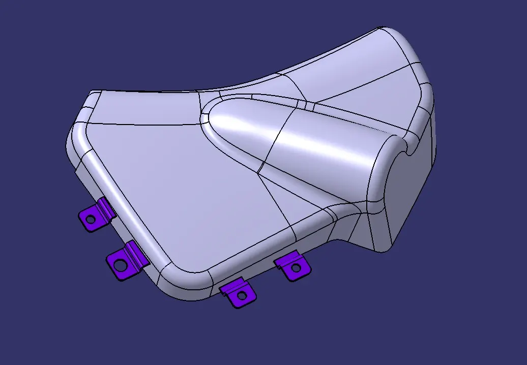
DRAFT ANALYSIS FOR THE FINAL PRODUCT WAS MENTION BELOW
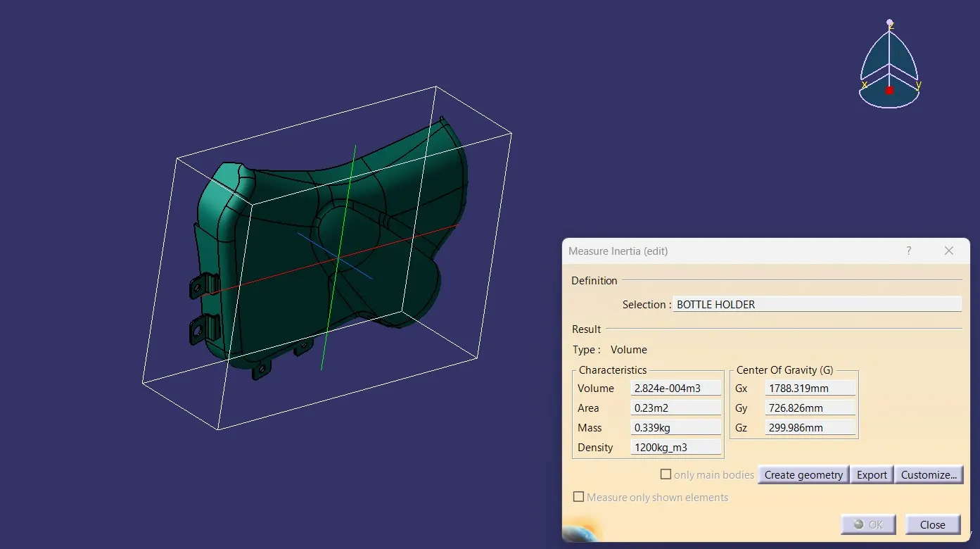
WEIGHT OF THE BOTTEL HOLDER IMAGE MENTION BELOW
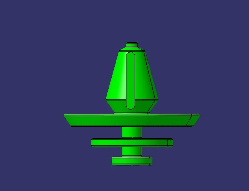
AND ASSEMBLE THE PUSH PINS IN THE TOP OF THE DOG HOUSE
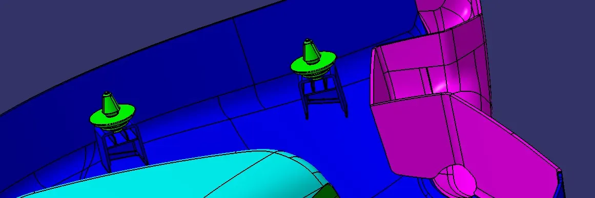
OVER ALL ASSEMBLY OF THE DOOR TRIM PANEL IMAGE MENTION BELOW
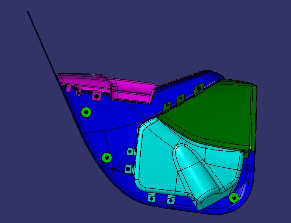
PARTING LINE:
A parting line is a borderline in which draft angles change direction. That means, it is the dividing line that splits the core and cavity halves of a moulded part. It is sometimes a starting point for the mould parting surface.
PARTING SURFACE:
Parting Surface is the point of a plane where the cavity meets the core in a larger area with zero tolerance gap and prevents the leakage of the molten metal out from the mould.And the parting surface is from the outside of the component.
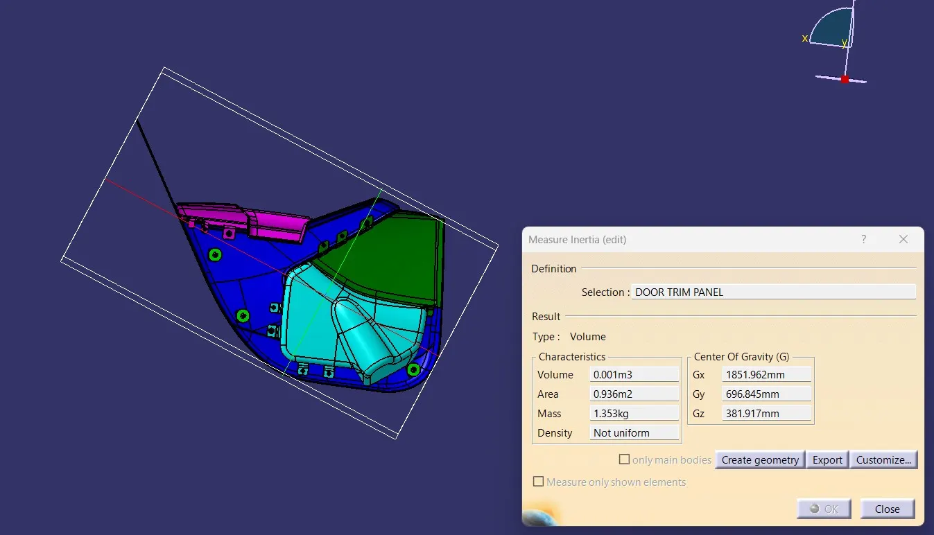
ISOMETRIC VIEW
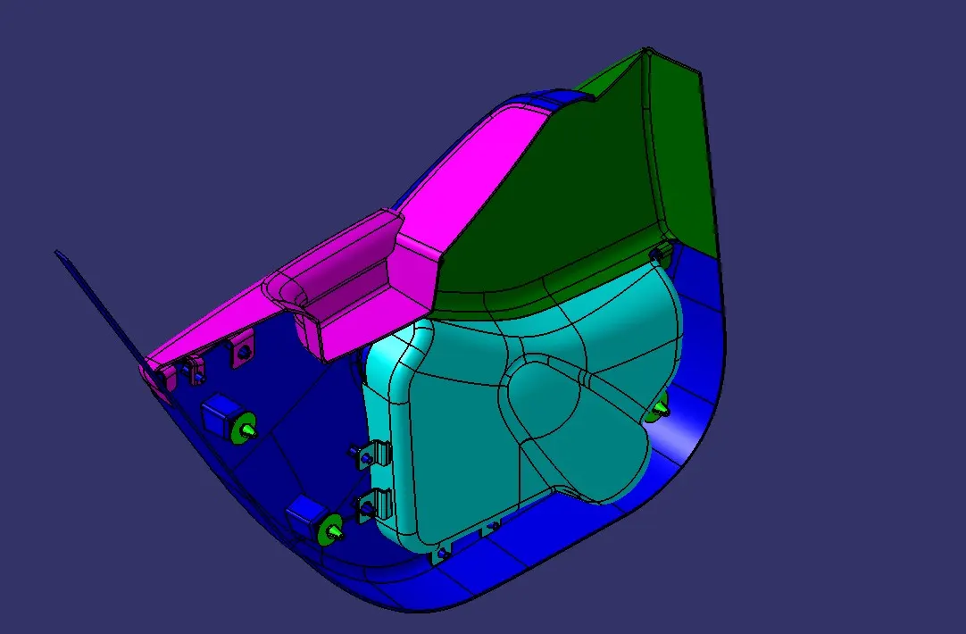
FRONT VIEW
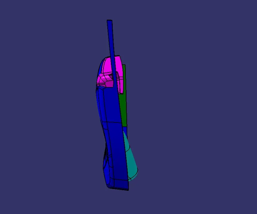
RIGHT SIDE VIEW
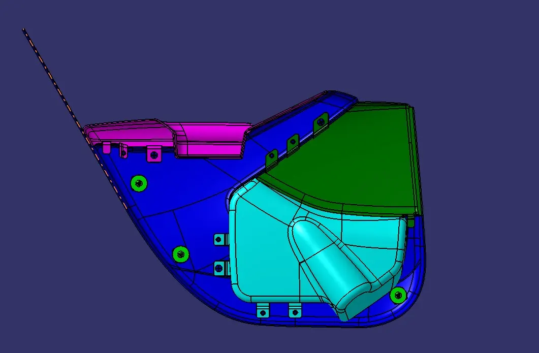
TOP VIEW
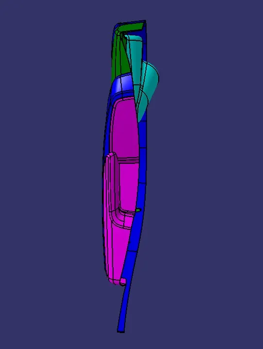
CONCLUSION:
Here We Development of a Door Trim panel We find the attachment strategy for the door panel and Use Push pin with Dog house for Lower substrate for Door panel attachment.considering all the Injection moulding Rules and limitations and Design rules are followed the for the Ease of Manufacturability.