Week 12- Final project
WEEK 11 - FINAL PROJECT
BUSINESS CASE: DEVELOPMENT OF A DOOR TRIM PANEL
TARGET: To Achieve easily producible plastic mold parts with respective engineering features and design creations.
I HAVE CREATED AN ASSEMBLY PRODUCT FILE FROM THE INPUT SKIN SURFACE FILE.
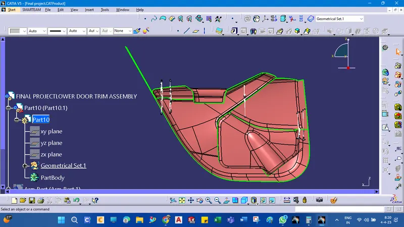
As am using the save management options to save inside the assembly product and individual part files in the same product itself. then I have to hide the input surfaces only I keep the part file for the master section separately.
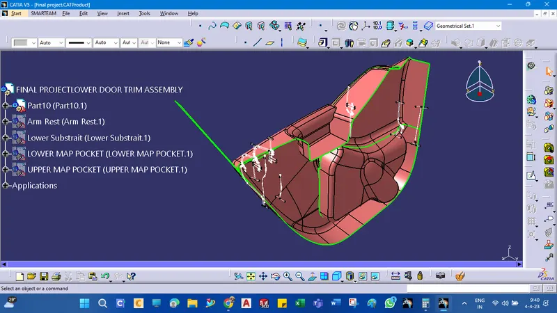
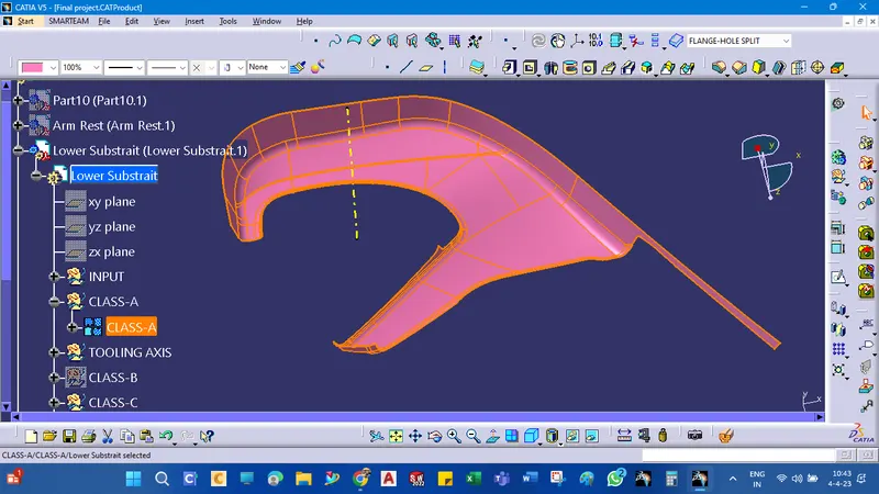
LOWER SUBSTRATE CREATIONS
Class A Surface was given is checked and found out it is perfectly closed boundaries, no further action to be taken.
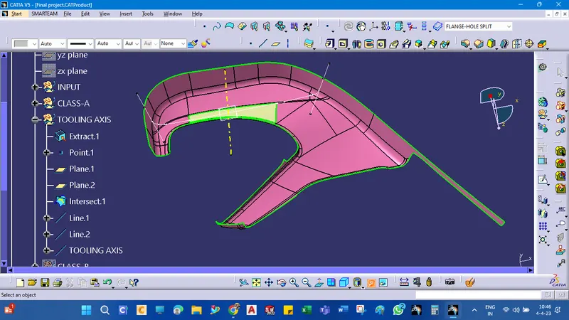
TOOLING AXIS CREATIONS
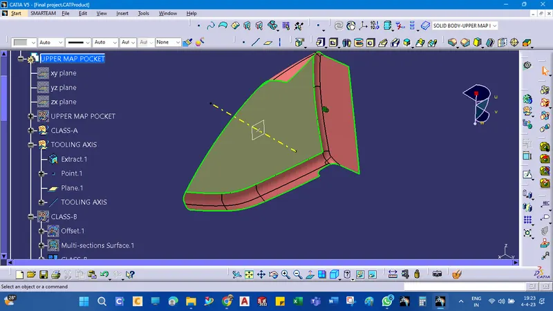
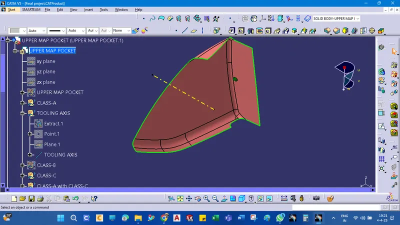
First, I extracted the class-A surface to create a point on the surface, also made a plane parallel through the point, and made the plane with 'Zx' PLANE TO CHOOSE The axis system', by using the intersection command, take the intersection line to create the line with a bisecting method to perform the draft analysis. accordingly,
DRAFT ANALYSIS FOR CLASS-A SURFACES
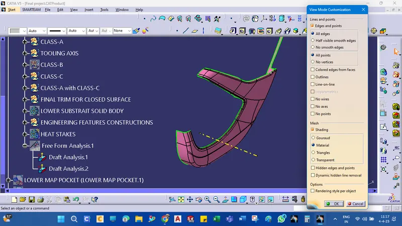
Change the view to the MATERIAL mode for draft analysis
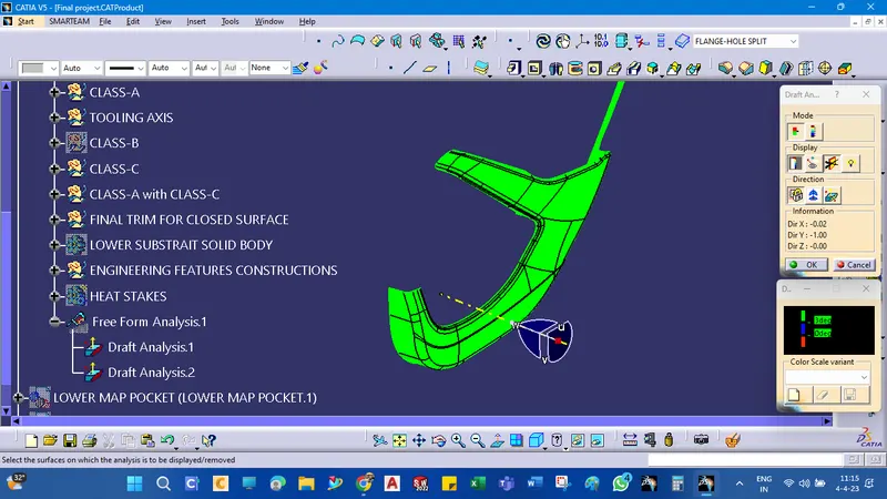
select the compass function to align the compass to the tooling direction and lock the direction using the lock function in the draft analysis toolbar
the surface is showing green color so that the surface clears the minimum draft angle of 0.5 to 3 degrees
Using the analyses under the running point we can check the draft angle on the individual faces. It shows how many drafts are on specific points when we move the cursor point.
Green color - above 3 degrees positive draft
blue color- below 0 degree
Red color -between 3 and 0
CLASS-B SURFACE CREATIONS
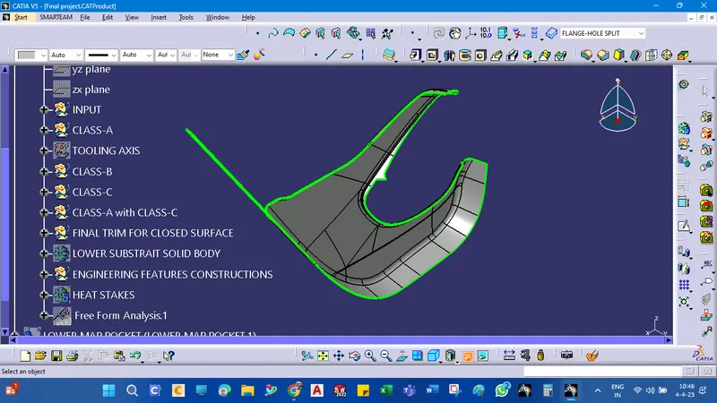
Class B surface is created by using the offset command to offsetting the Class A surface by 2.5 mm as per the master section.
CLASS-C SURFACE CREATIONS
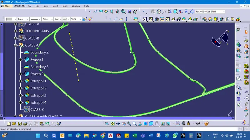
This surface connects the Class A and Class B surfaces. (Surface in between Class A & B surfaces)
Procedure to build Class C surface:
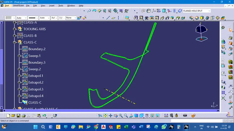
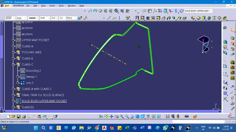
Since it is a complex class-A surface, don't simply create the class-A boundary curve and sweep it in one shot. Hence, we need to create smaller boundaries using the boundary command and then create a sweep of 90 degrees concerning the surface option if the class C should come perpendicular to the tooling axis. Sweeps at the areas where class C should come parallel to the tooling axis should have a 3-degree draft value concerning the tooling axis to pass the draft analysis. Also, at the fillet/curve areas, use a multi-section surface to sweep and complete the class C surface and do the same for class-C hole surfaces.
Join every individual sweep using the join command and for the edges which haven't joined, extrapolate and trim off the sweep surface corners at the required edges.
The Class-C Surface is:
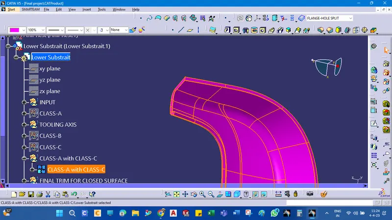
CLASS-A with CLASS-B SURFACES
select and JOIN the CLASS-A-With CLASS-C Surfaces and CLASS-B surfaces
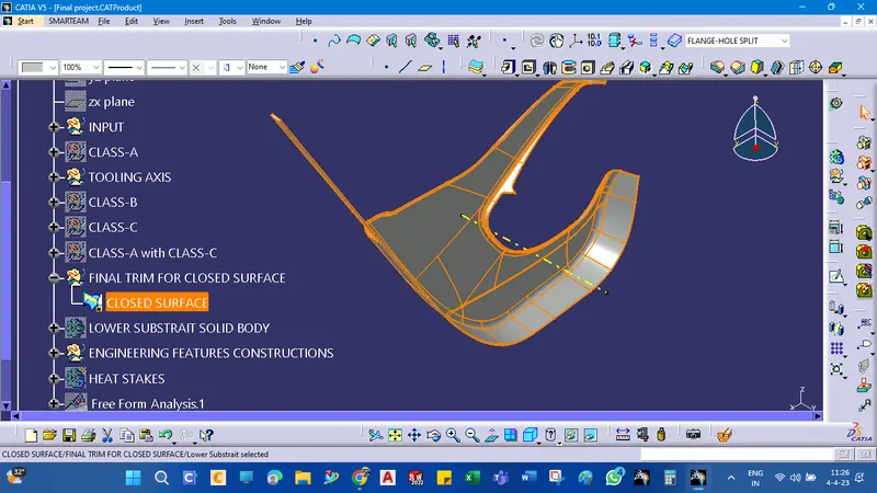
FINAL TRIM TO GET SOLID SURFACES
To perform the final trimming, select and JOIN the CLASS-A-With CLASS-C Surfaces and CLASS-B surfaces
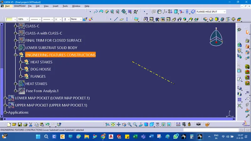
ENGINEERING FEATURES CREATIONS
HEAT STAKES CREATIONS
Heat Stake features are commonly found in injection molding designs. They are used to aid in the assembly of molded parts by providing a channel for a screw. Their primary use is to strengthen holes or slots in the surface present in the part model.
Design rules consider while creating a Heat stake
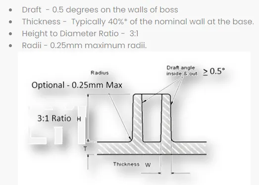
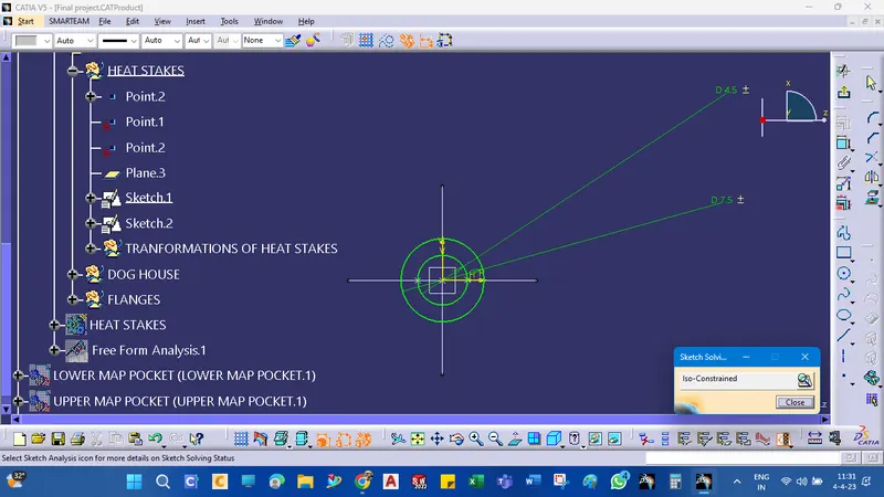
Heat Stake The design begins with the proper geometrical set and uses the positioned sketches to get the screw boss and heat stake sketch
A fully constrained sketch created
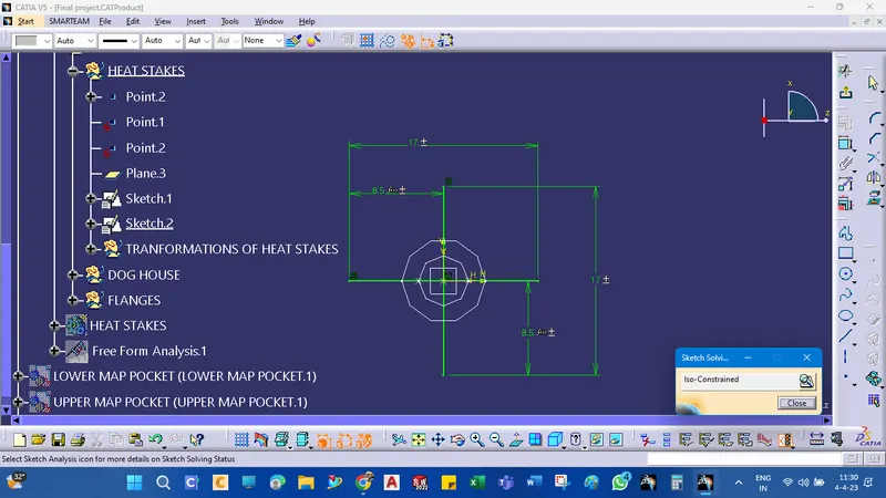
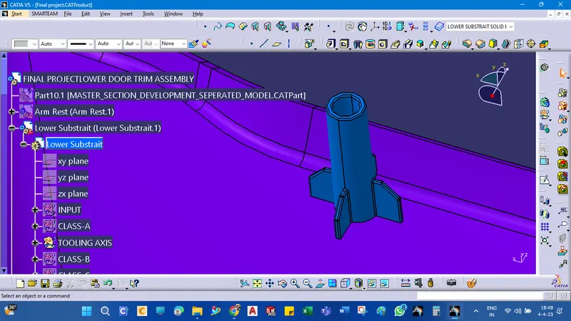
WITH SUPPORTING RIBS
A fully constrained sketch created
DOG HOUSE DESIGN
Dog houses are designed to avoid SINK MARK created on the CLASS-A surface by screw bosses and to solve the length issues when giving screw bosses which need to be assembled to other components.
It is also useful when perpendicular screw bosses are required on the part of the tooling direction.
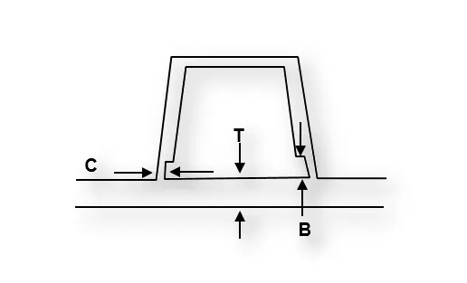
- C thickness should be 40% of the main wall thickness of T
- The minimum width of the dog house is 12 mm.
- The height of B should be 3-6 mm
- The minimum draft for the do house is 1.5 degrees to die draw.
Procedure for creating the DOG HOUSE
- The first step is to create a side core axis.
- I have chosen normal the point method for creating the side core tooling axis.
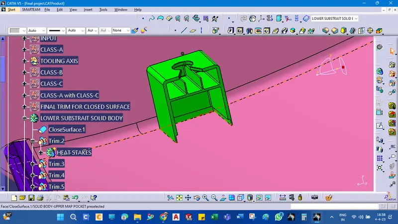
SIDE CORE TOOLING AXIS CREATIONS
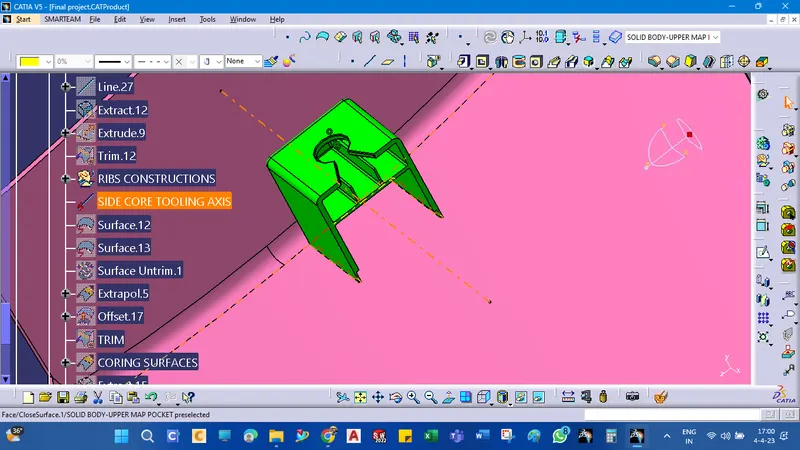
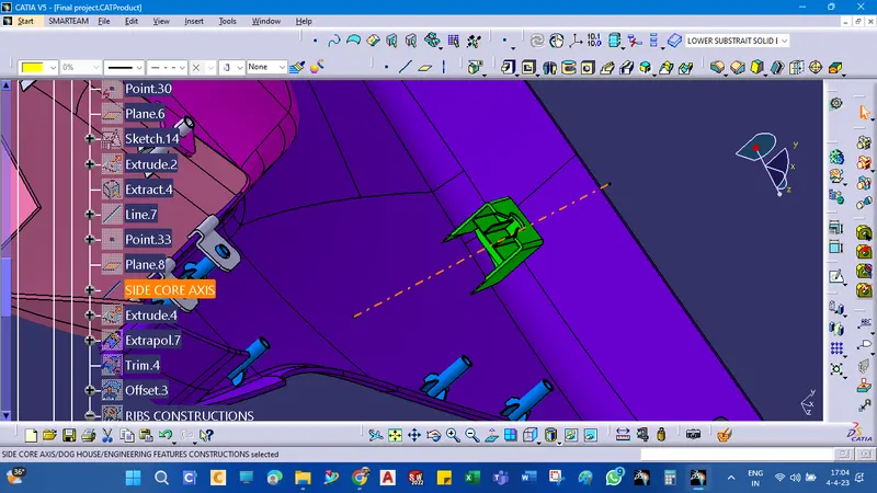
FINAL LOWER SUBSTRATE
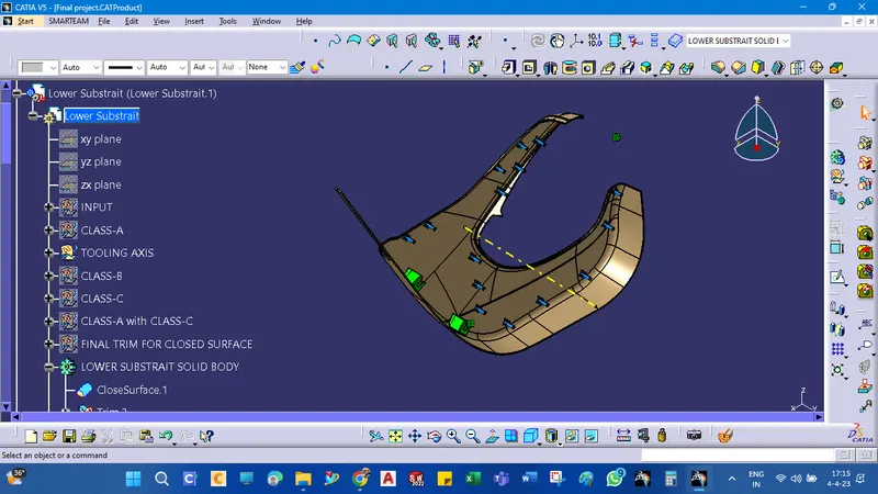
DRAFT ANALYSIS OF LOWER SUBSTRATE
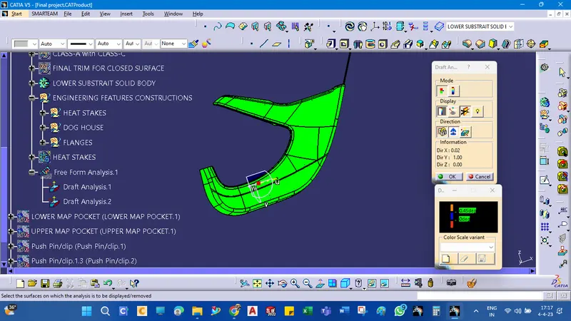
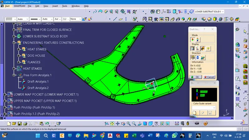
select the compass function to align the compass to the tooling direction and lock the direction using the lock function in the draft analysis toolbar
the surface is showing green color so that the surface clears the minimum draft angle of 0.5 to 3 degrees
Using the analyses under the running point we can check the draft angle on the individual faces. It shows how many drafts are on specific points when we move the cursor point.
Green color - above 3 degrees positive draft
blue color- below 0 degree
Red color -between 3 and 0
CLASS-A SIDE CLEAR FOR THE DRAFTING ANGLES
CLASS-B SIDE IS ALSO CLEAR FOR DRAFTING ANGLES TO GO FURTHER
ARMREST DESIGN
Class A Improvement:
First I have found that Class A that been given open boundaries
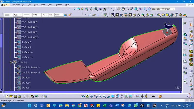
Rework and patches clear by the multiple extract and trim, extrapolate and join command
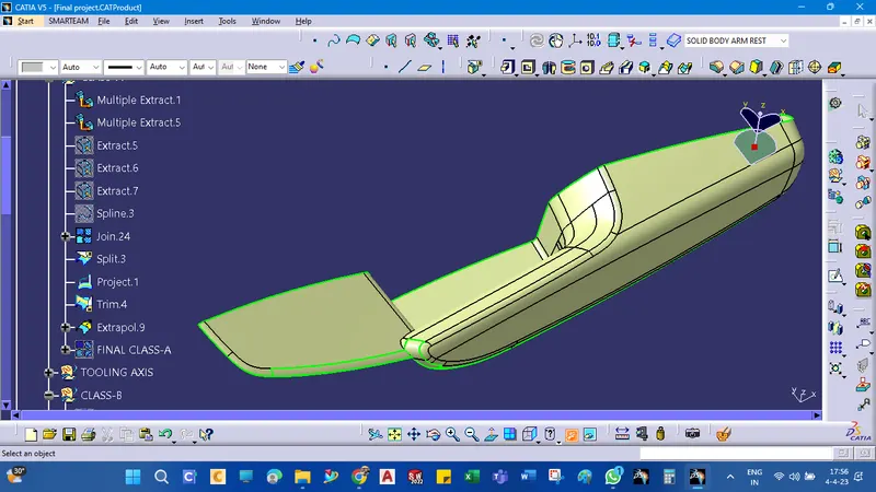
improved class-A surface
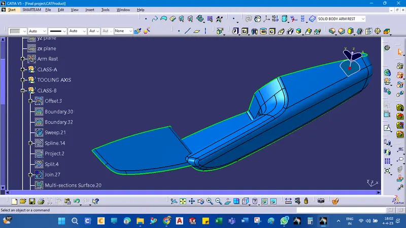
TOOLING AXIS CREATIONS for armrest
First, I extracted the class-A surface to create a point on the surface, also made a plane parallel through the point, made the plane with 'xy' axis system', by using the intersection command, take the intersection line to create the line with a bisecting method to perform the draft analysis. accordingly, I made another bisecting line with an opposite side plane


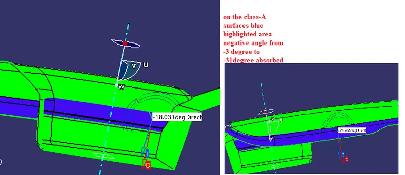
DRAFT ANALYSIS FOR ARMREST
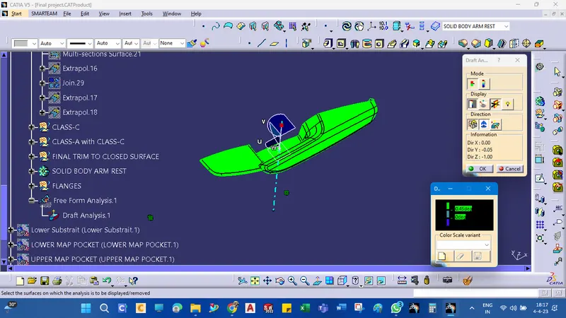
CLASS-B SURFACES CREATIONS
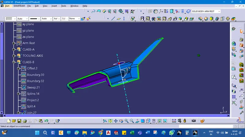
While offsetting the class-A surfaces to the inward direction, with a 2.5mm thickness of the given plastic parts. I solved the class-B surfaces by finding some gap surfaces, as given below.
Rework the patches and discontinuity of the offset surfaces using the features like extract, multi-extract, sweep, multi-section surfaces, extrapolate, Trim, split, and fillets.
To ensure the continuity of the Class-B surfaces check the boundary command to find out the boundary.
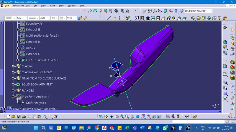
FINAL CLASS-B SURFACES
Class B surface offset of 2.5mm is given below:
CLASS-C SURFACE CREATIONS
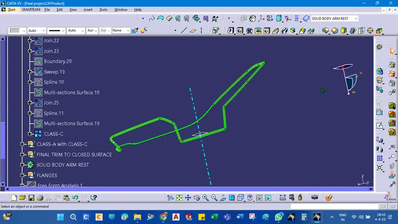
This surface connects the Class A and Class B surfaces. (Surface in between Class A & B surfaces)
Procedure to build Class C surface:
Since it is a complex class-A surface, don't simply create the class-A boundary curve and sweep it in one shot. Hence, we need to create smaller boundaries using the boundary command and then create a sweep of 90 degrees concerning the surface option if the class C should come perpendicular to the tooling axis. Sweeps at the areas where class C should come parallel to the tooling axis should have a 3-degree draft value concerning the tooling axis to pass the draft analysis. Also, at the fillet/curve areas, use a multi-section surface to sweep and complete the class C surface and do the same for class-C hole surfaces.
Join every individual sweep using the join command and for the edges which haven't joined, extrapolate and trim off the sweep surface corners at the required edges.
The Class-C Surface is:
CLASS-A with CLASS-B SURFACES
select and JOIN the CLASS-A-With CLASS-C Surfaces and CLASS-B surfaces
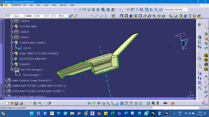
FINAL TRIM TO GET SOLID SURFACES
To perform the final trimming, select and JOIN the CLASS-A-With CLASS-C Surfaces and CLASS-B surfaces
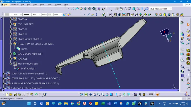
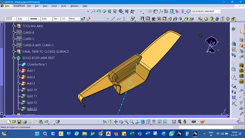
DOOR TRIM SOLID SURFACES
Go to Part Design and make the final trim close body.
ARMREST FLANGE CREATIONS
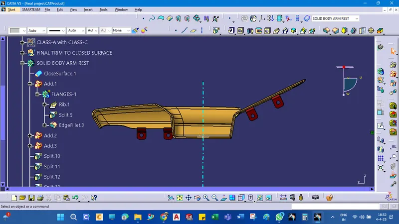
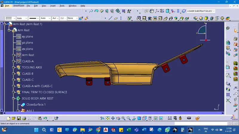
In order to Join the Armrest body with the other bodies, I created 4 Flanges separately with counter holes, Flanges are different based on the engineering features that will be held. Then these flanges are assembled to the main body (Armrest) by an un-trim feature.
Each Flange was created by extracting the surface from Class C Surface added by Generative Surface. then I applied a close surface feature to create the flange body, Drafted by 0.5 deg, Filleted. Also, it is important to mention that the counter holes were created by iso-constrained, positioned sketches and then padded it and drafted before it was removed from the main flange.
 `
`
LOWER MAP POCKET DESIGN (BOTTLE HOLER)
CLASS-A SURFACES
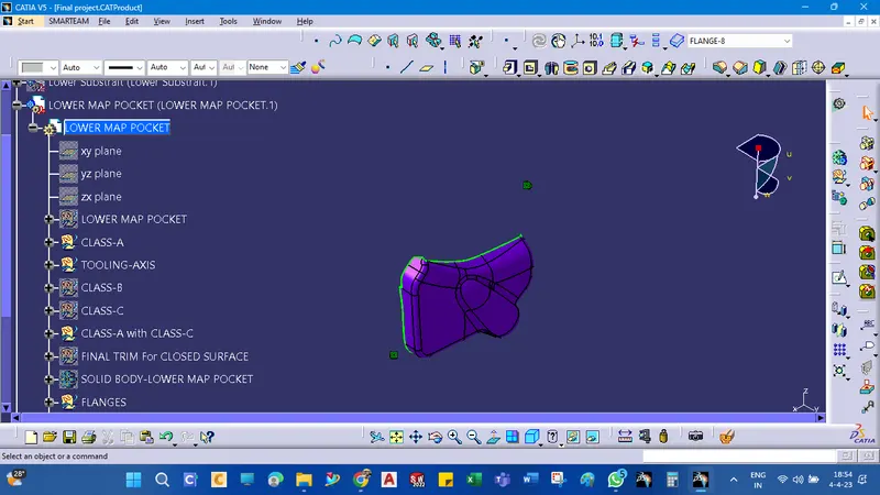
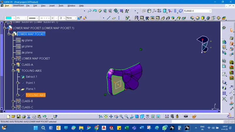
TOOLING AXIS CREATIONS FOR LOWER MAP POCKET(bottle holder)
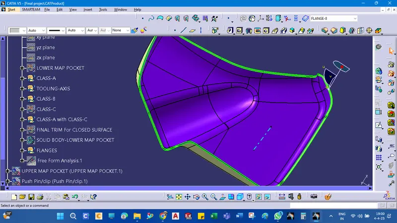
CLASS-B SURFACE CREATIONS
for the class-B surface to offset the 2.5mm materials' nominal thickness should be outside the directions
CLASS-C SURFACES CREATIONS
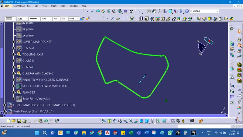
CLASS-A with CLASS-B SURFACES
select and JOIN the CLASS-A-With CLASS-C Surfaces and CLASS-B surfaces
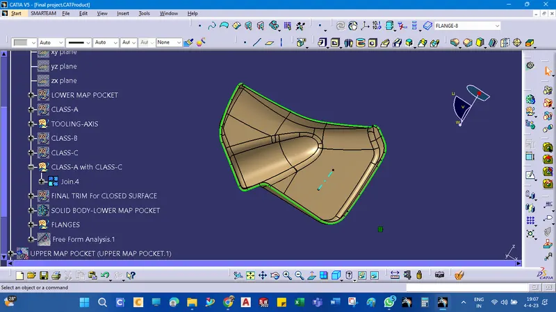
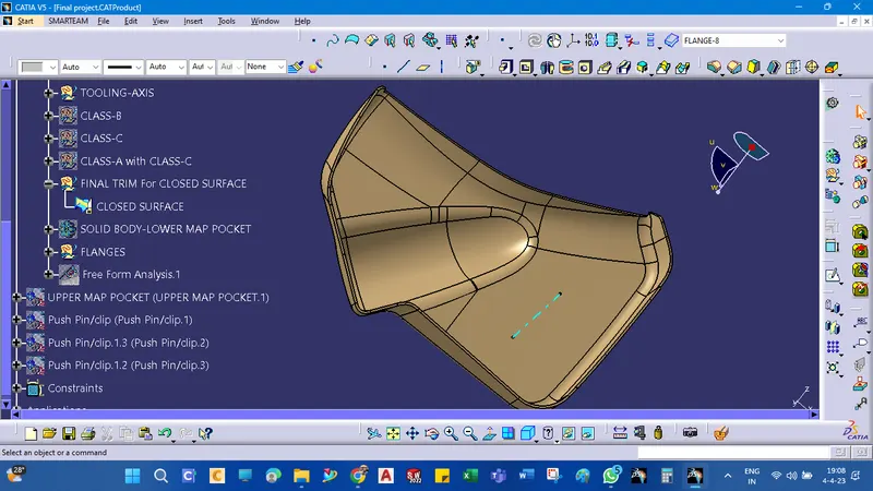
FINAL TRIM TO GET SOLID SURFACES
To perform the final trimming, select and JOIN the CLASS-A-With CLASS-C Surfaces and CLASS-B surfaces
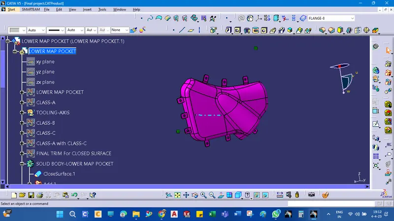
FLANGES CREATIONS
In order to Join the Bottle Holder with the other bodies, I created 3 Flanges separately with counter holes, Flanges are different based on the engineering features that will be held. Then these flanges are assembled to the main body (Bottle Holder) by an un-trim feature.
Each Flange was created by extracting the surface from Class C Surface added by Generative Surface. then I applied the close surface feature to create the flange body, Drafted by 0.5 deg, Filleted. Also, it is important to mention that the counter holes were created by iso-constrained, positioned sketches and then padded and drafted before it was removed from the main flange.
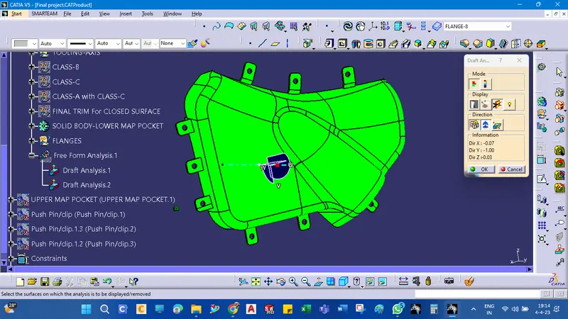
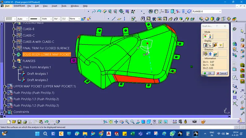
SOME OF THE RED COLORS MENTIONED ON SURFACES ARE ABSORBED AS NEGATIVE DRAFT ANGLE
By applying drafting analysis at 2.9 Deg, we can see most bodies are been cleared. As Green is set at 2.9 degrees, blues is Zero, and less than Zero it is red colored. As is shown in the next image in Class A Surface some negatives cannot be cleared by a draft angle of 3 Deg. it is suggested to be reported back to the drafter in real life but as this is a study project, ill be ignoring this
UPPER MAP POCKET DESIGN
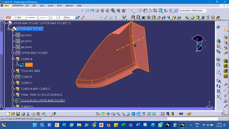
CLASS- A SURFACE CREATIONS
BY USING THE JOIN COMMAND simply created
TOOLING AXIS CREATIONS
CLASS-B SURFACE CREATIONS
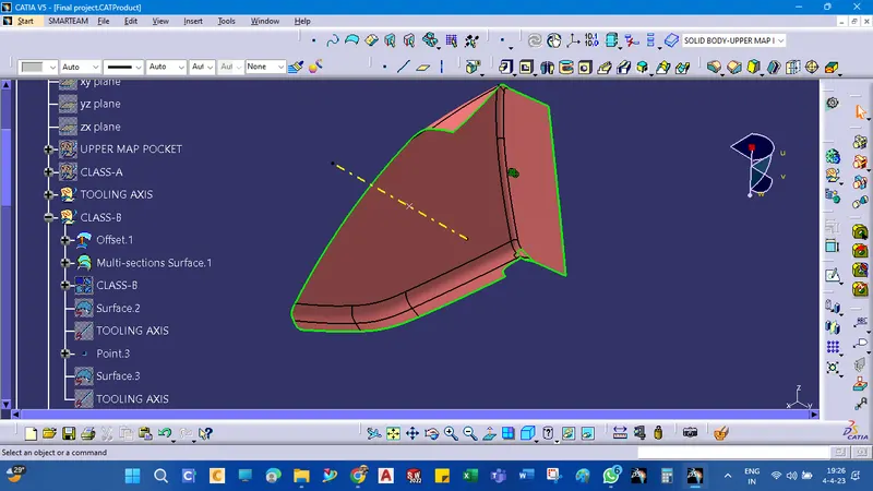
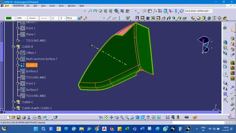
While offsetting the class-A surfaces to the inward direction, with a 2.5mm thickness of the given plastic parts. I solved the class-B surfaces by finding some gap surfaces, as given below.
Rework the patches and discontinuity of the offset surfaces using the features like extract, multi-extract, sweep, multi-section surfaces, extrapolate, Trim, split, and fillets.
To ensure the continuity of the Class-B surfaces check the boundary command to find out the boundary.
CLASS-C SURFACE CREATIONS
This surface connects the Class A and Class B surfaces. (Surface in between Class A & B surfaces)
CLASS-A with CLASS-B SURFACES
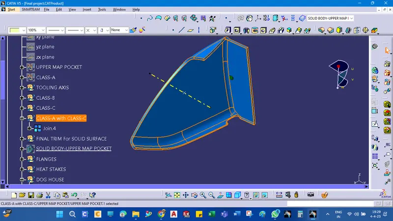
select and JOIN the CLASS-A-With CLASS-C Surfaces and CLASS-B surfaces
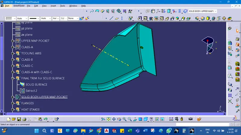
FINAL TRIM TO GET SOLID SURFACES
To perform the final trimming, select and JOIN the CLASS-A-With CLASS-C Surfaces and CLASS-B surfaces
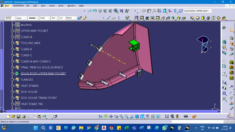
ENGINEERING FEATURES ARE CREATED AS SHOWN BELOW THE PICTURE
FLANGES HEAT STRAKE AND ONE DOG HOUSE CREATED
As it is required to go further process
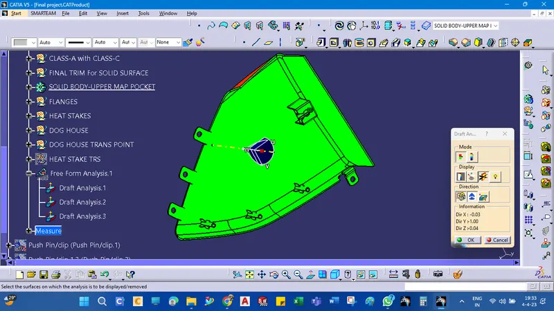
DRAFT ANALYSIS FOR UPPER MAP POCKET
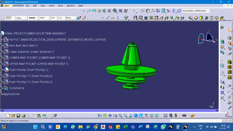
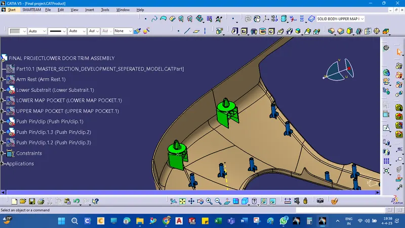
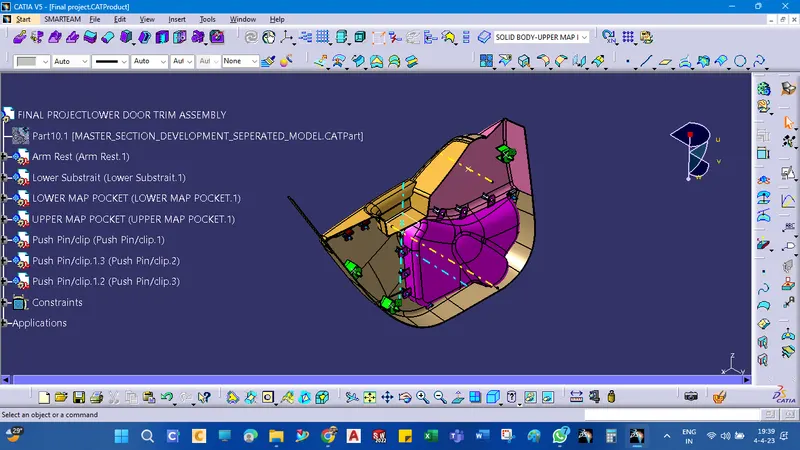
PUSH PIN ASSEMBLY
As I have created two Dog Houses for this part assembly, I need to import two Push pins.
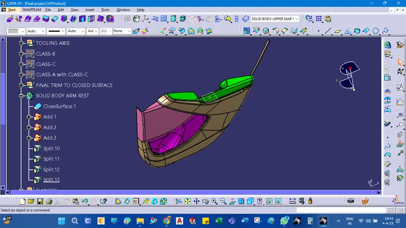
Both are assembled correctly as shown:
ALSO PUBLISHED ALL COMPONENTS
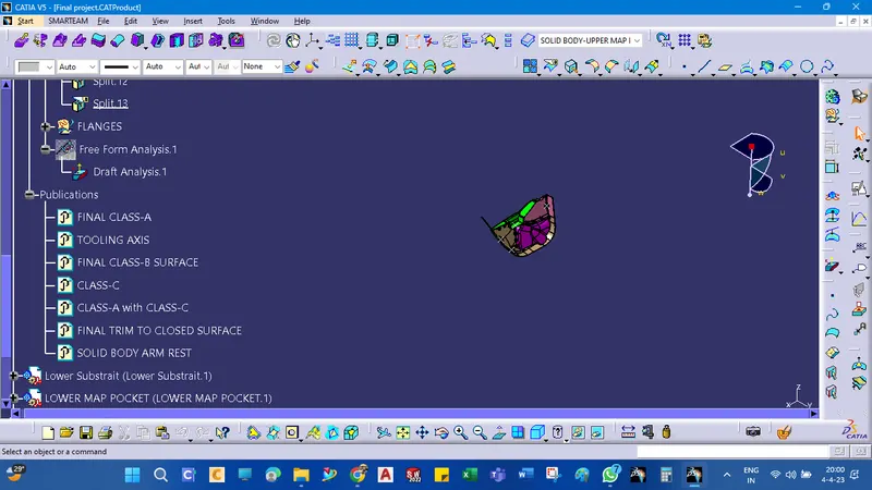
PLEASE REFER TO THE MORE DETAILS IN THE ATTACHED FILE
REGARDS
SATHISH