Week 12- Final project
AIM:-
To develop a door trim panel with the given inputs and to create engineering features with the given master section for the attachment of components.
DESCRIPTION:-
- To create a thickened part using master section reference.
- To create the mounting features as per design guidlines in the industry and with master sections.
- To create a proper tooling axis and do draft analysis.
- To create the attachment features using given master section and attachment strategy of our own which will be as per industry guidelines.
- Here i created the parts using Top-down approach.
CLASS A SURFACE IMPROVEMENT:-
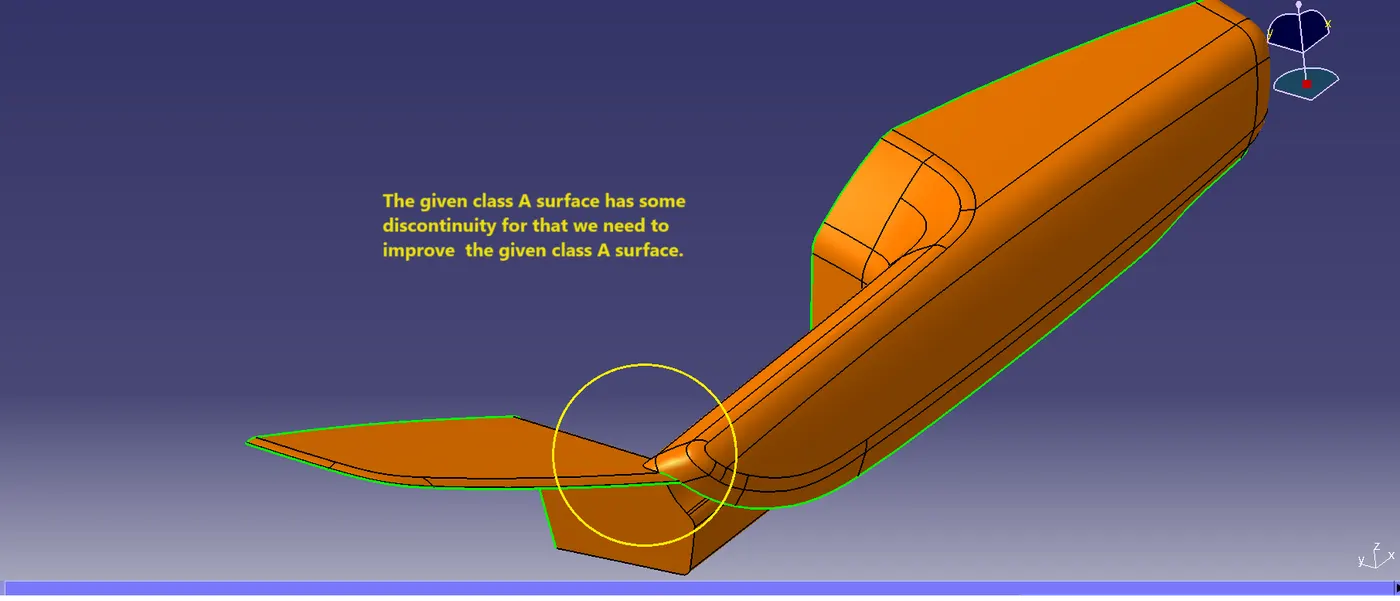
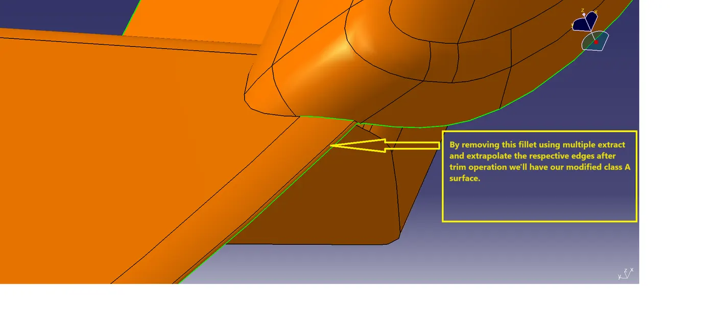
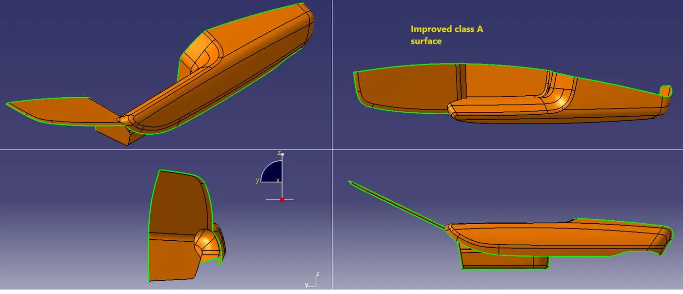
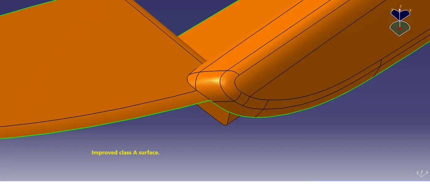
The given class A is having certain discontinuity as mentioned in above image in order to have a continuos surface we need to modify the given class A.
IMPROVED CLASS A:-
TOOLING DIRECTION FOR ARM REST:-
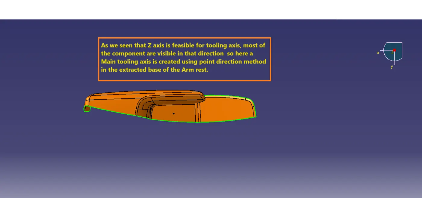
The Main tooling axis is created w.r.to the Z axis direction.
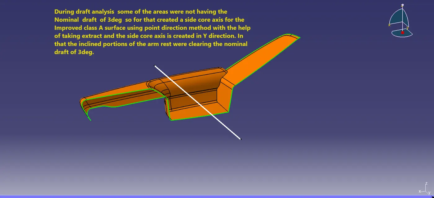
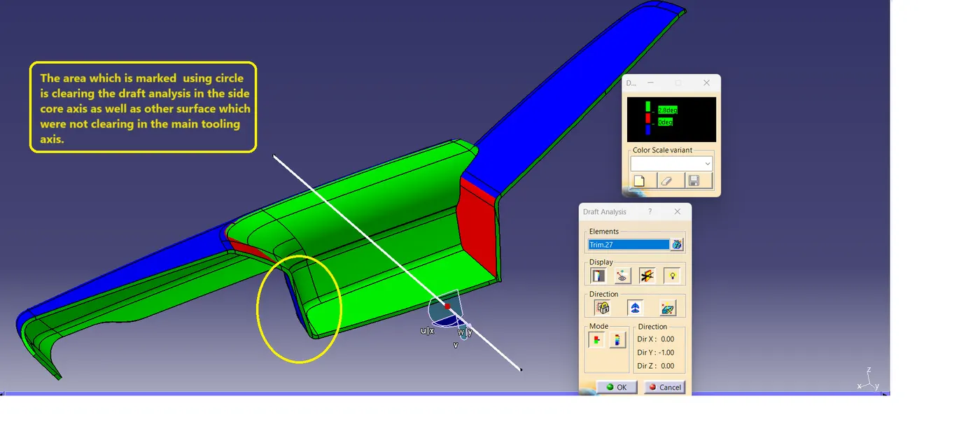
The side core axis is created in the Y direction.
DRAFT ANALYSIS OF GIVEN CLASS A :-
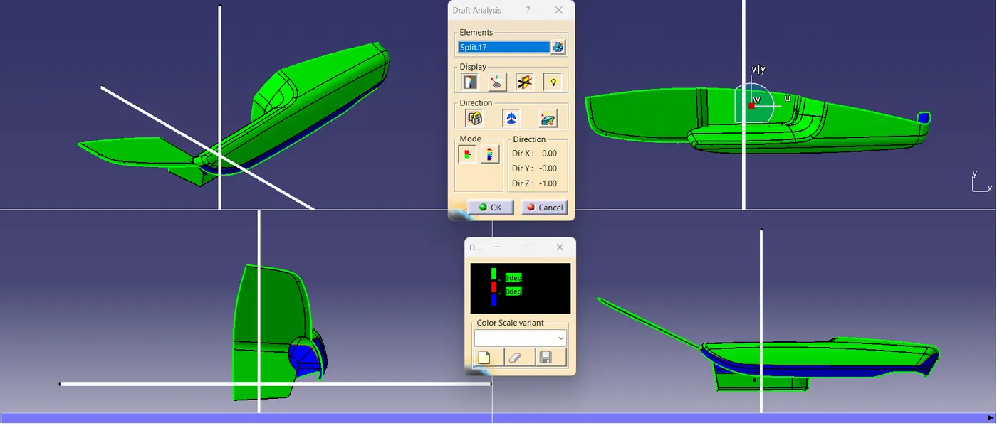
As mentioned already in main tooling axis some of the area were not clearing the nominal draft of 3deg. For that side core axis was created.
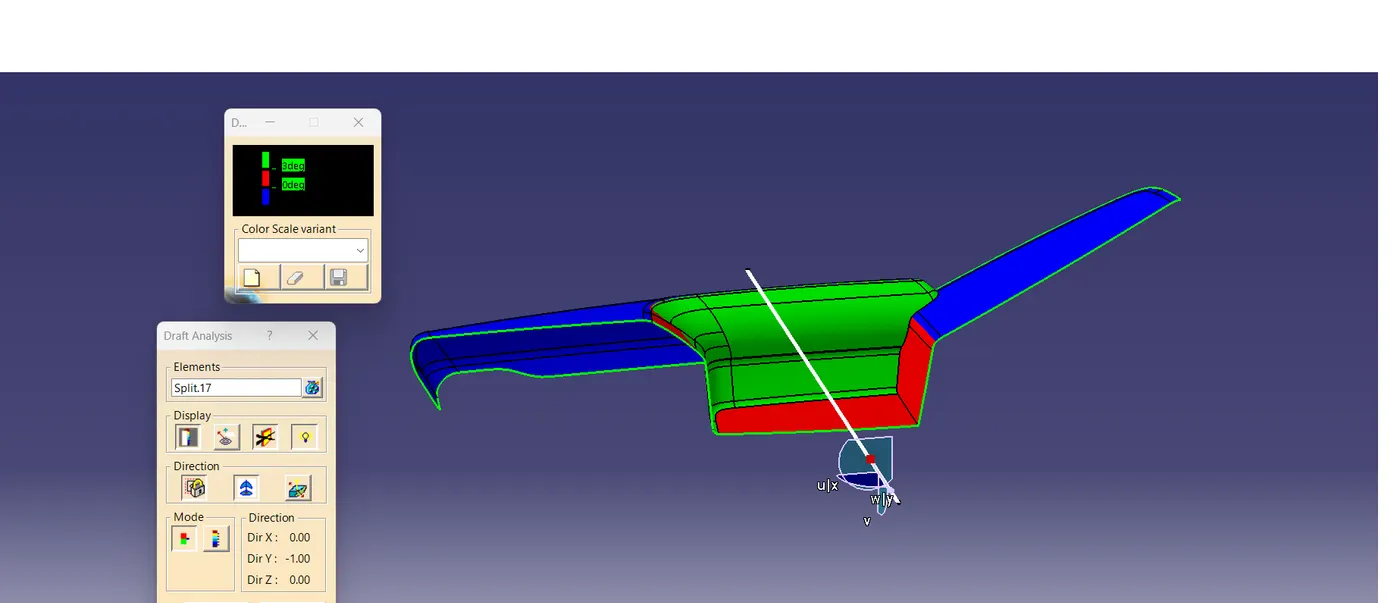
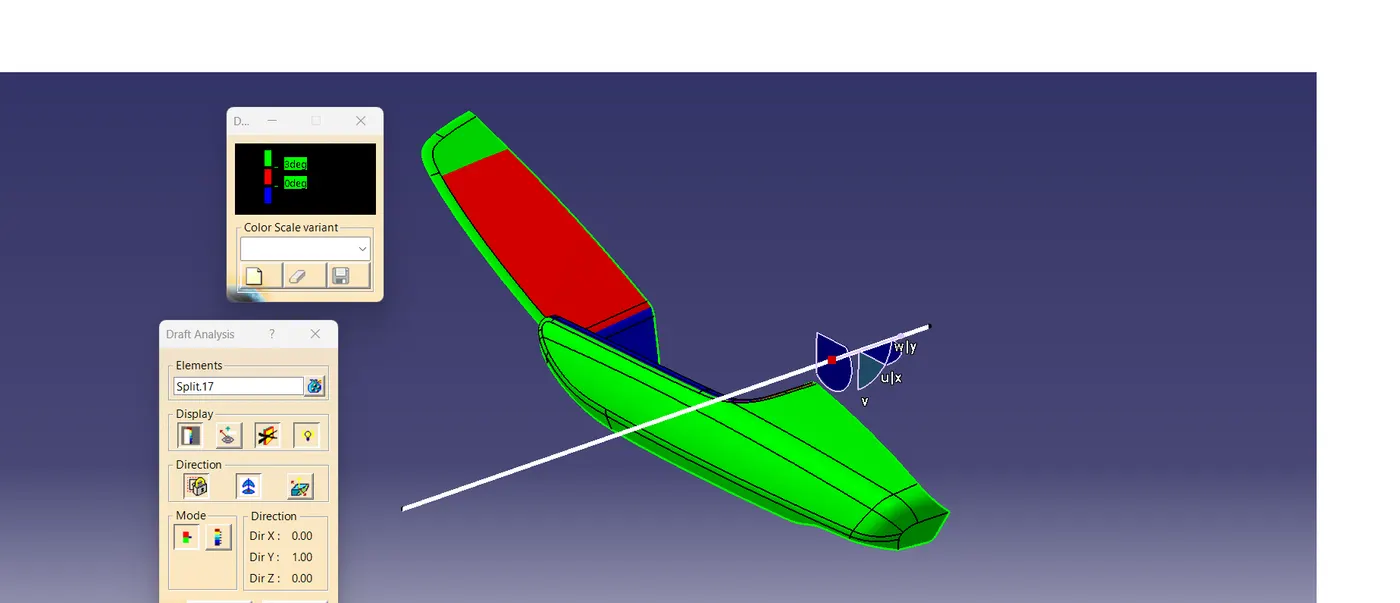
The portions which are not cleared in main tooling axis was cleared in side core axis.
CLASS B SURFACE CREATION:-
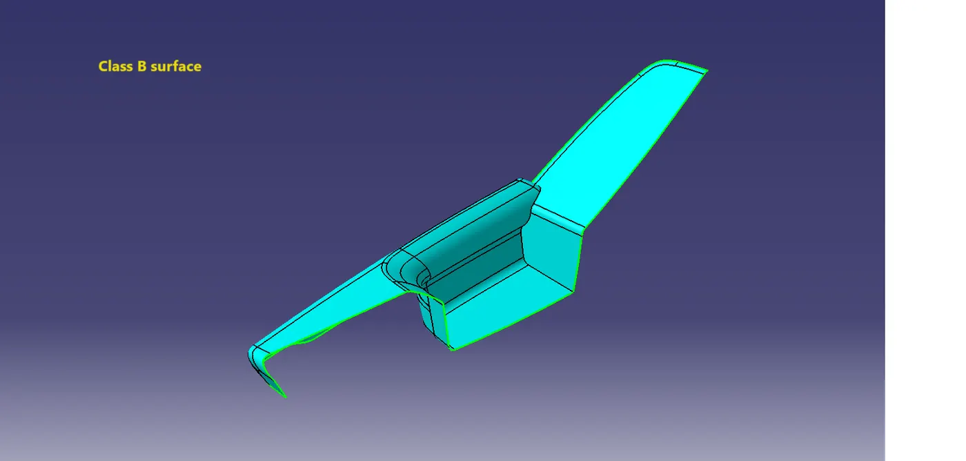
Class B surface was created using the direct offset method.
CLASS C CREATION:-
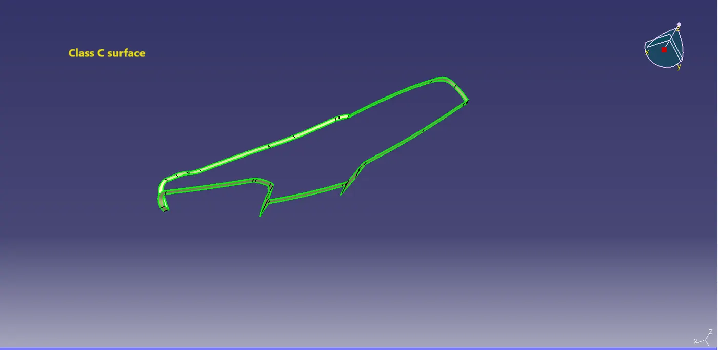
The class C surface were created using both the draft direction method and reference to surface method using sweep command. Some of the area were C surface will not intersect with the class B surface if we create using the draft direction method, inorder to create a closed surface we need to create the C surface accordingly by using both the reference and draft direction method .
CLASS A&C JOIN:-
CLOSED SURFACE OF ARM REST:-
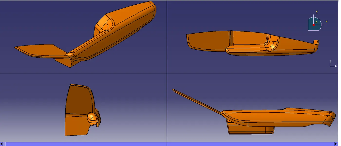
As mentioned in the master section the thickness of the component is 2.5mm.
DRAFT ANALYSIS OF ARM REST:-
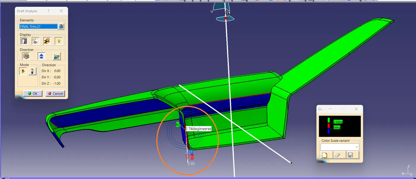
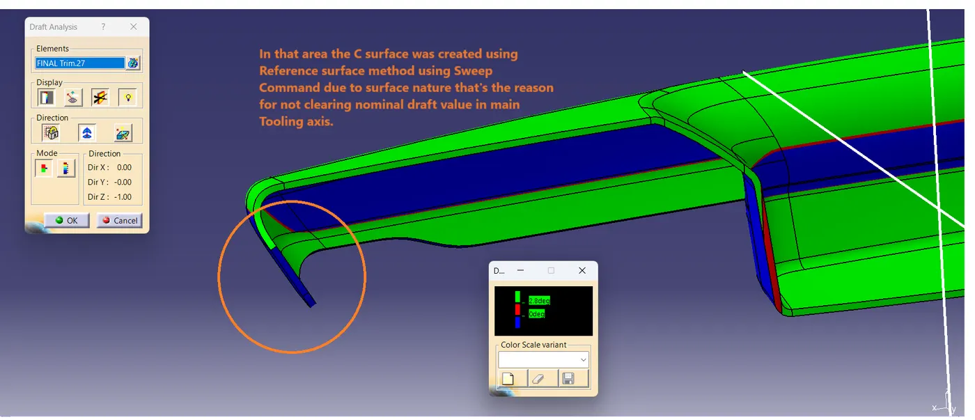
The main tooling direction draft analysis some of the C surface area which is parallel to the main tooling axis will not clear the draft analysis. In that area it is having the draft of 2.74deg as mentioned in the above image.
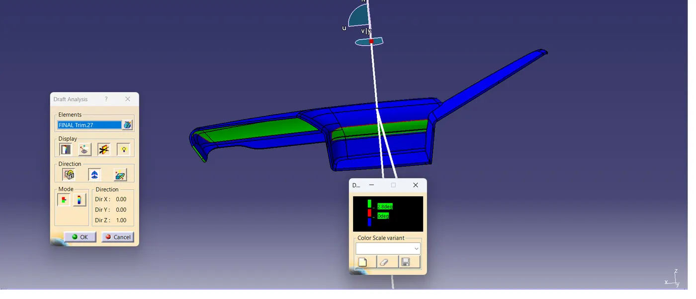
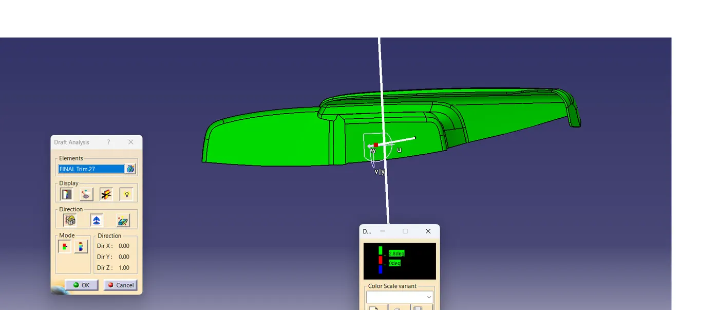
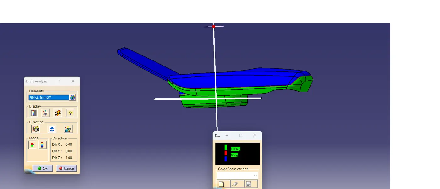
The above image shows the draft analysis of Class B surface.
SIDE CORE DRAFT ANALYSIS OF ARM REST:-
FLANGE CREATION ON ARM REST:-
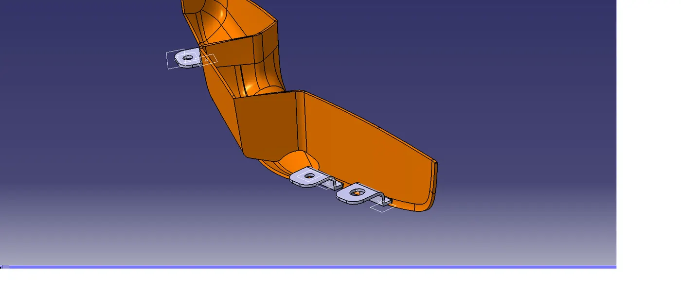
For the attachment strategy i have created flanges using reference from the master section and created a hole for the heat stake assembly from the lower substrate.
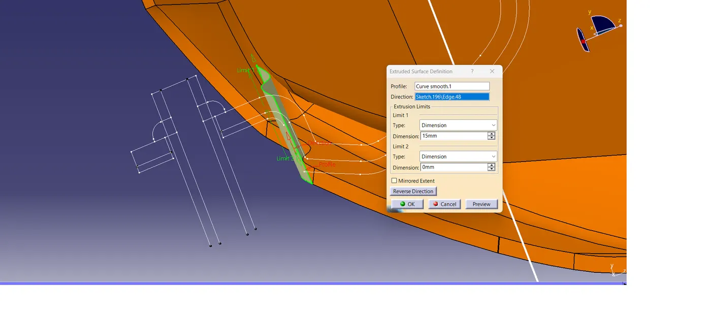
Created extract from the edges of the arm rest C surface and made into a smooth curve , then extruded along the direction of the mastersection.
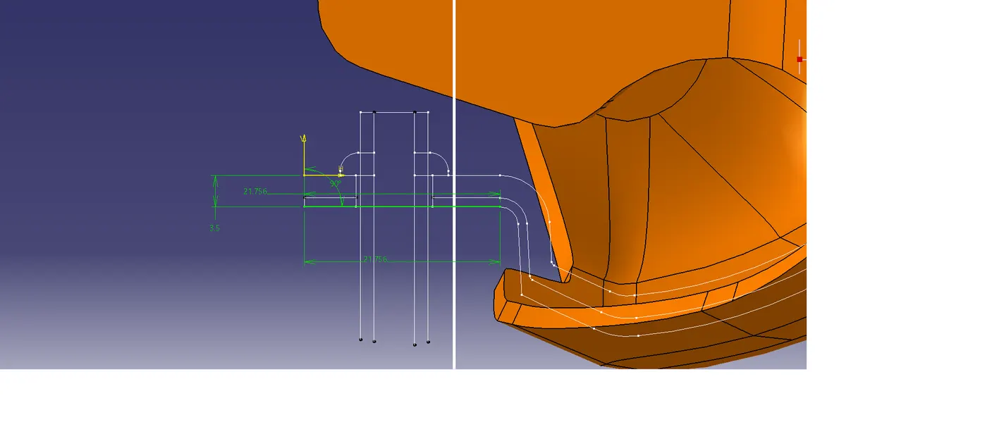
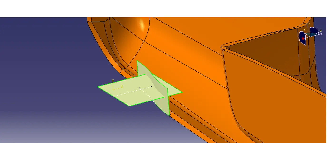
Created a sketch from the mastersection reference and extruded it to interfere with the another extruded surface which will help to trim.
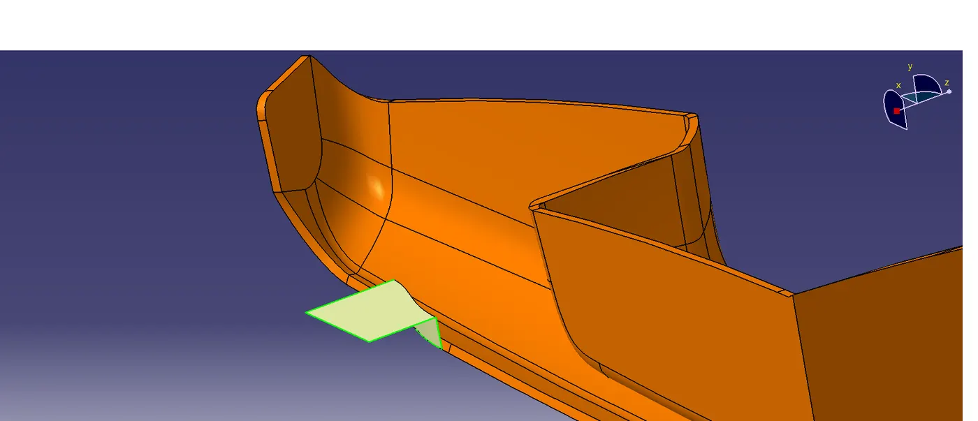
After the trim the flange surface is created for the Arm rest along the C surface with respect to the master section reference.
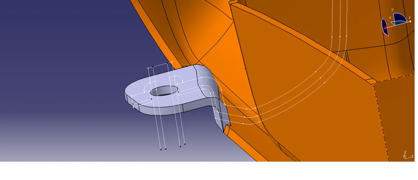
Thickenend the surface using thicken surface method and fillets were given as per the master section reference and assembled together with the arm rest. The hole also created using the reference from the master section , another two flanges were created on the other sides of the arm rest and all the required faces were drafted with minimum draft angle of 0.5deg.
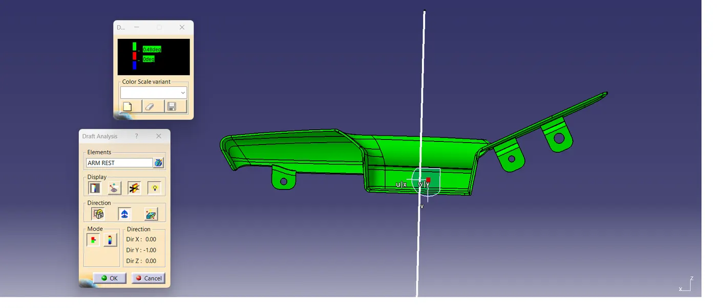
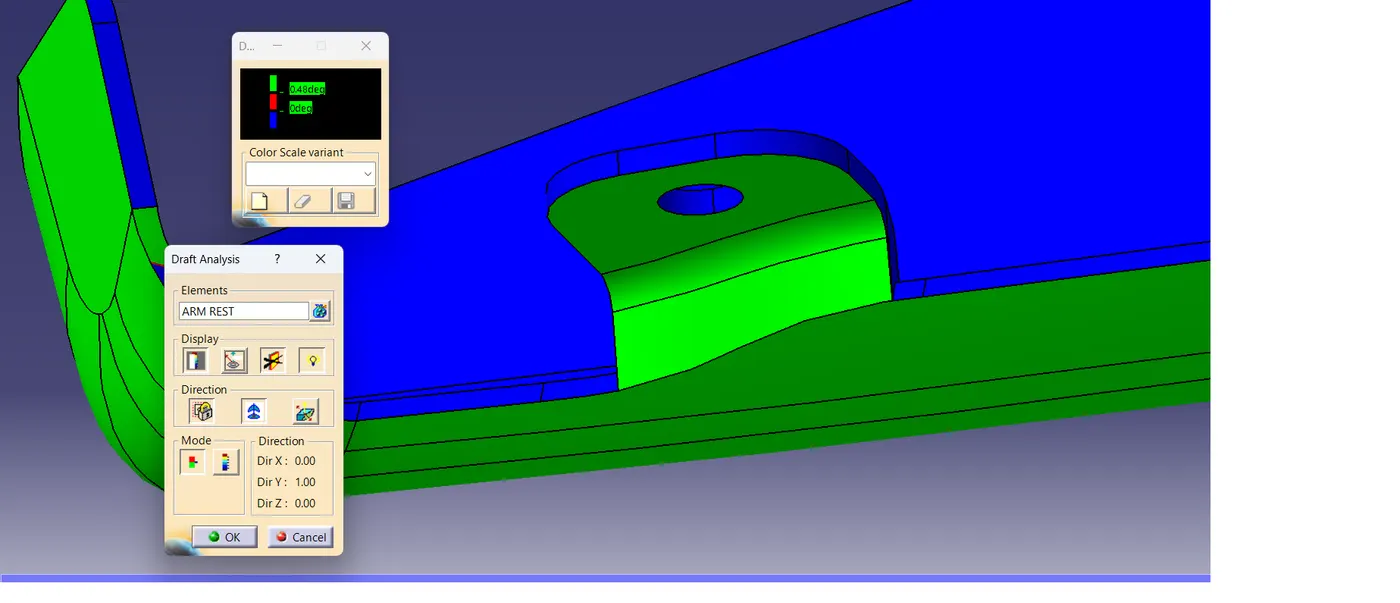
DRAFT ANAYSIS OF FLANGES:-
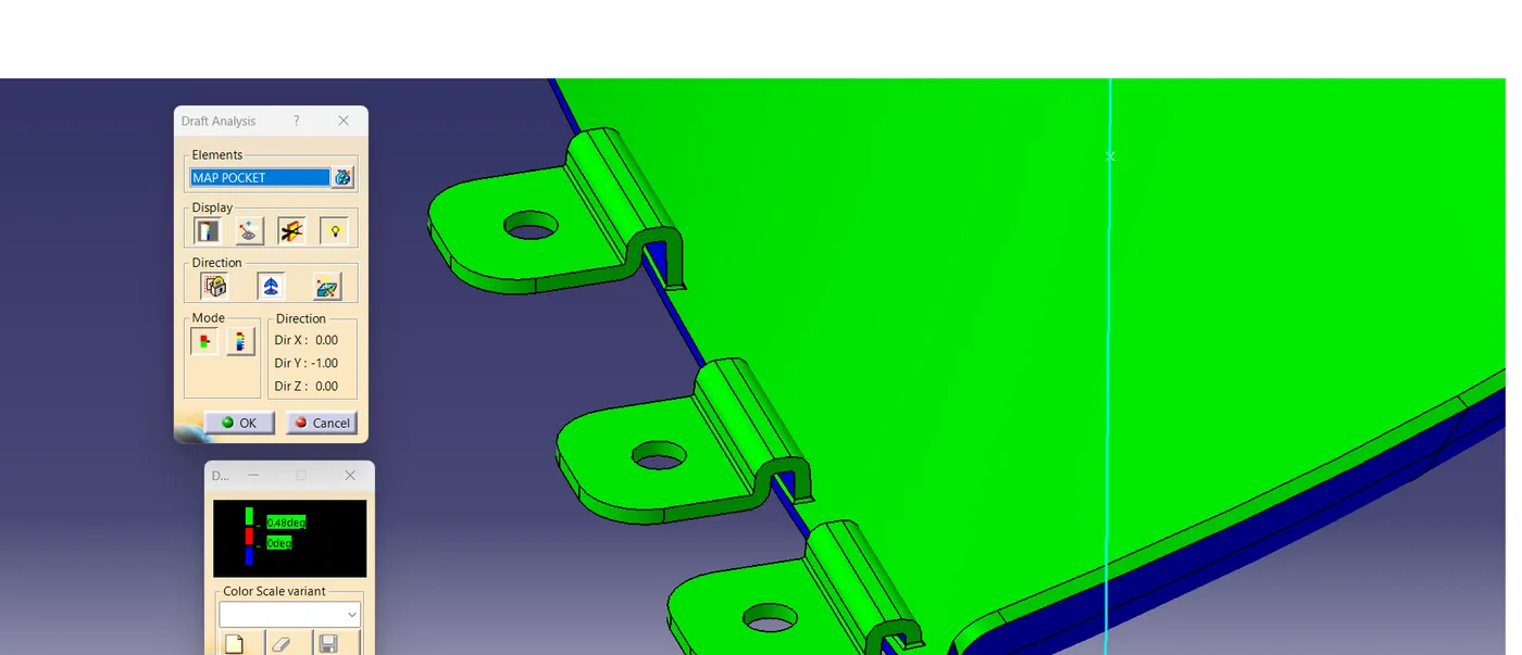
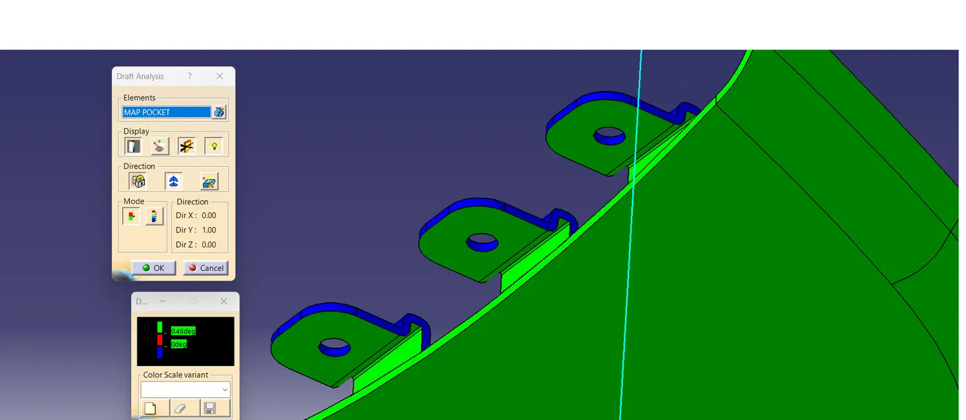
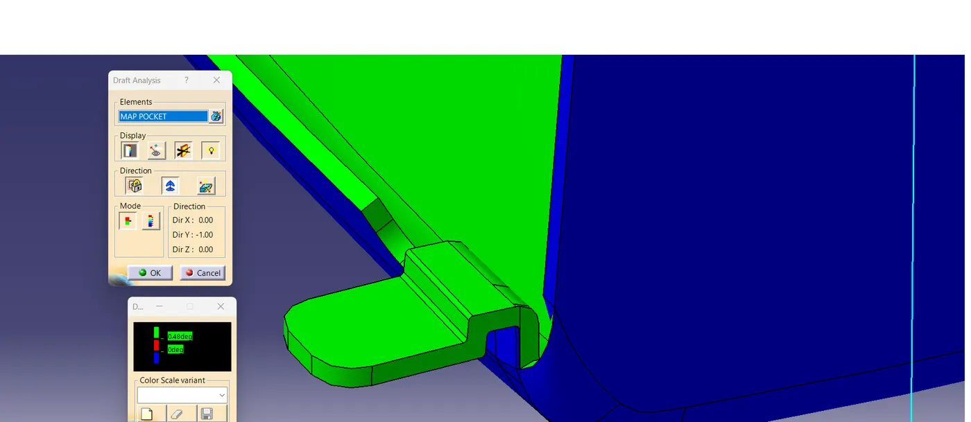
For the flanges and the holes draft were given along the side core axis.
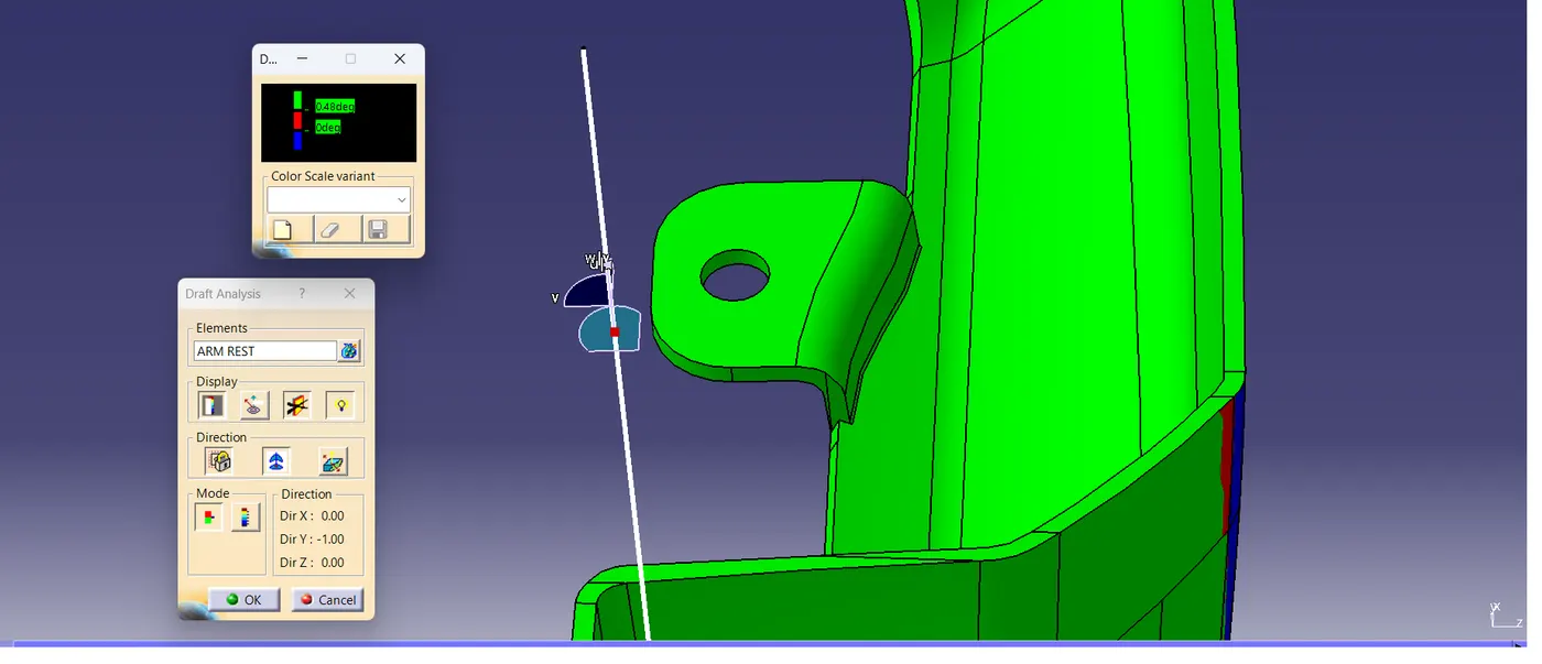
FINAL PART OF ARM REST IN 3D VIEWS:-
CLASS A SURFACE OF MAP POCKET :-
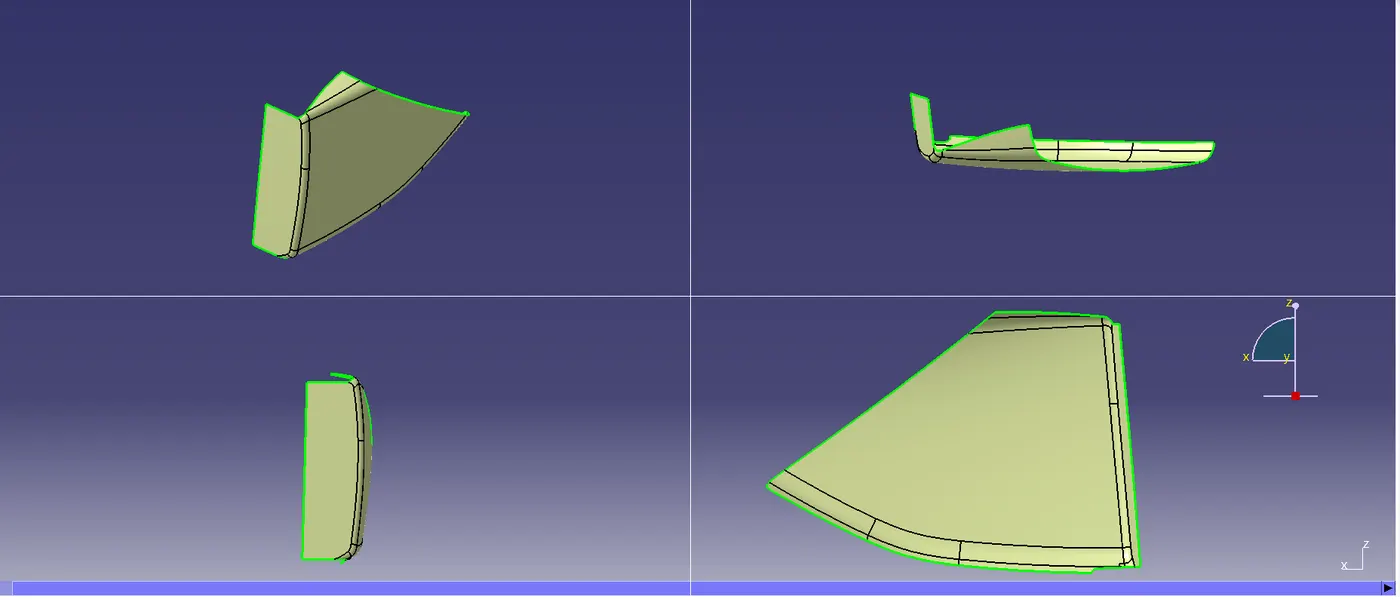
The given Class A surface has no discontinuity and the Y axis direction is feasible for tooling axis as we seen that the all the edges and corners were clearly visible.
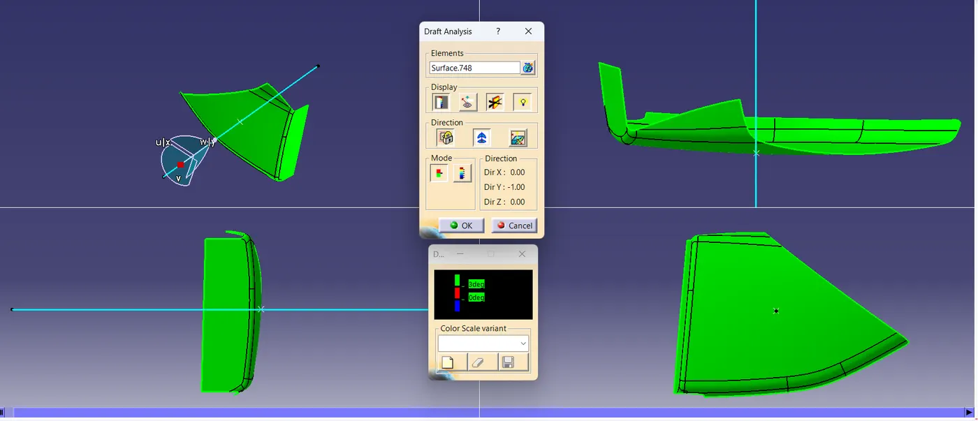
The tooling axis for the map pocket is created using point direction method along Y axis with the help of the extracted surface.
CLASS B SURFACE:-
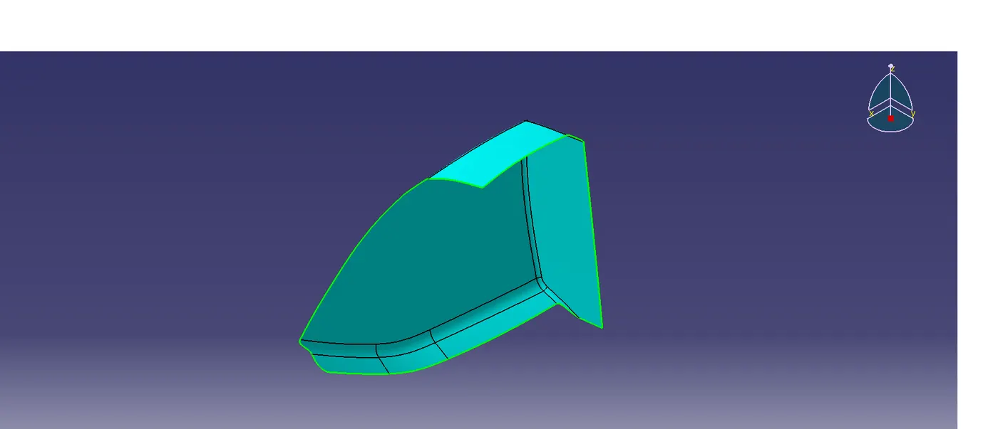
Class B surface is created using direct offset method and in some areas untrimed the surface and extrapolated and trimmed them together to form a Class B surface.
CLASS C SURFACE:-
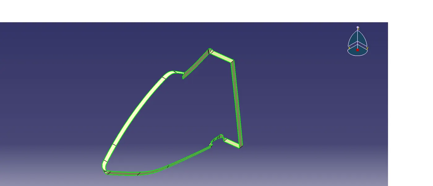
The Class C surface were created using both the draft direction method and reference surface method using sweep command.
CLOSED SURFACE OF MAP POCKET:-
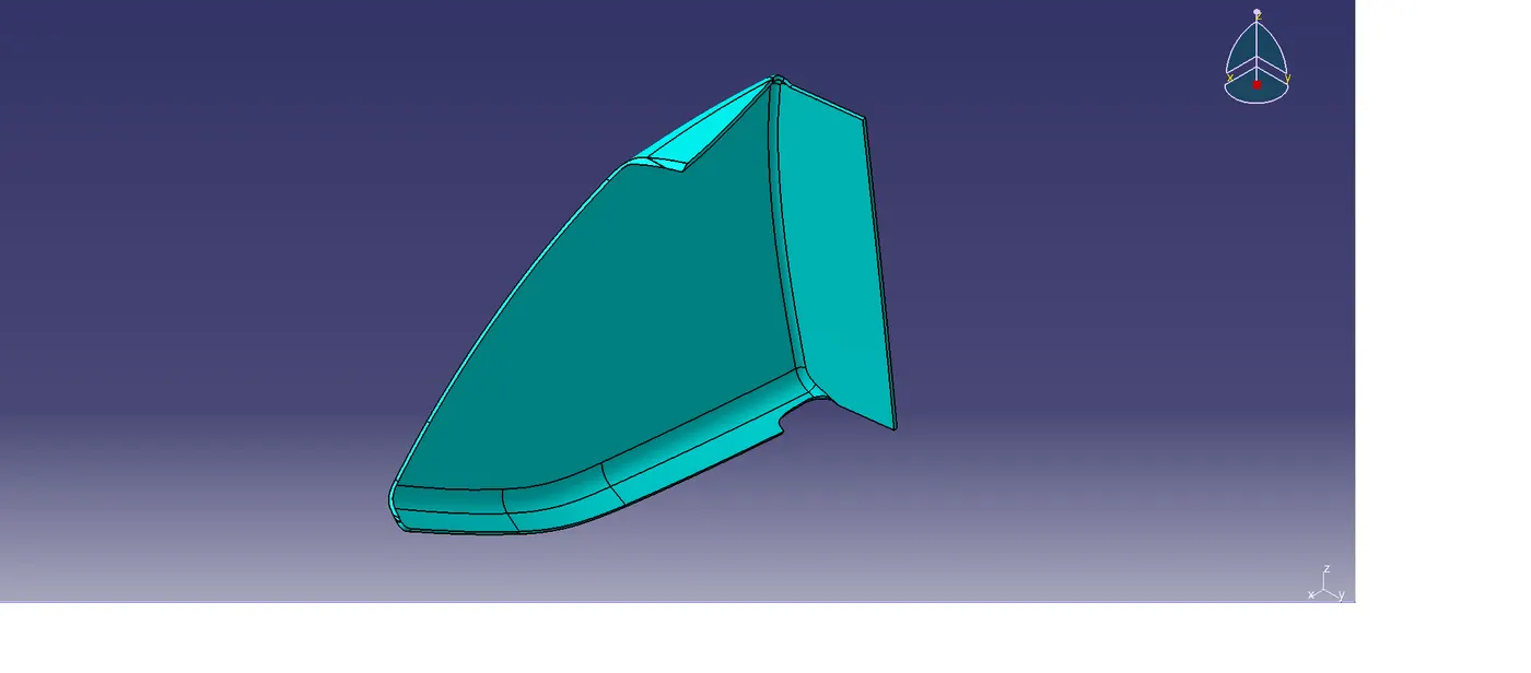
DRAFT ANALYSIS OF MAP POCKET:-
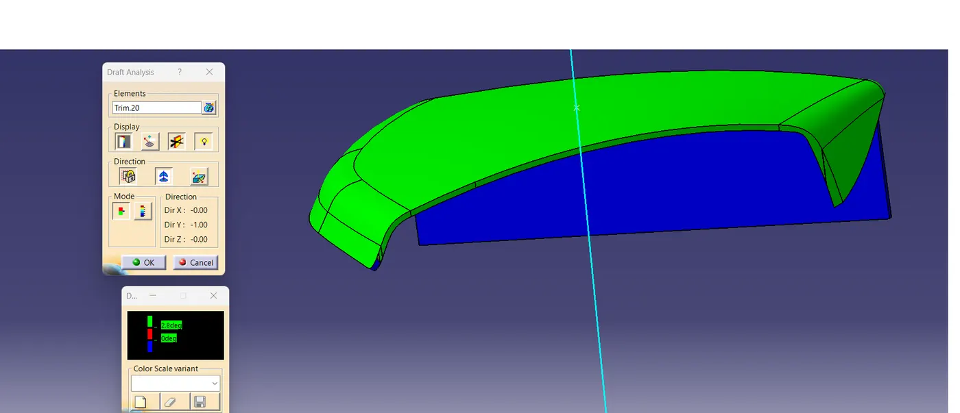
In that blue area the Class C surface is created using reference surface method so that the uniform thickness is achieved and these edges are not intersecting with the bottle holder part.
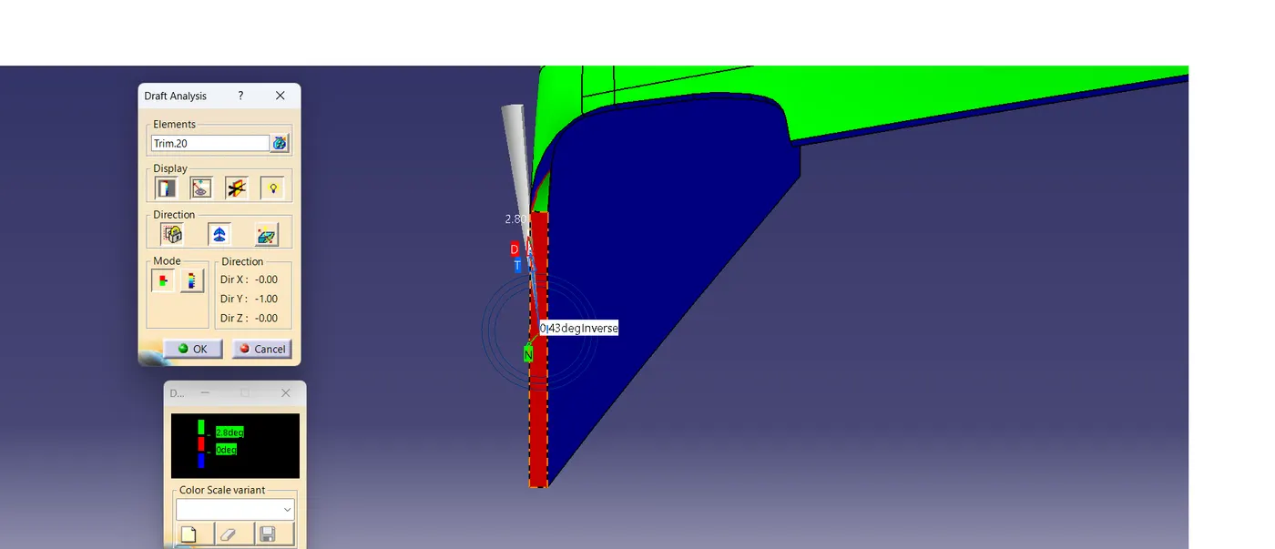
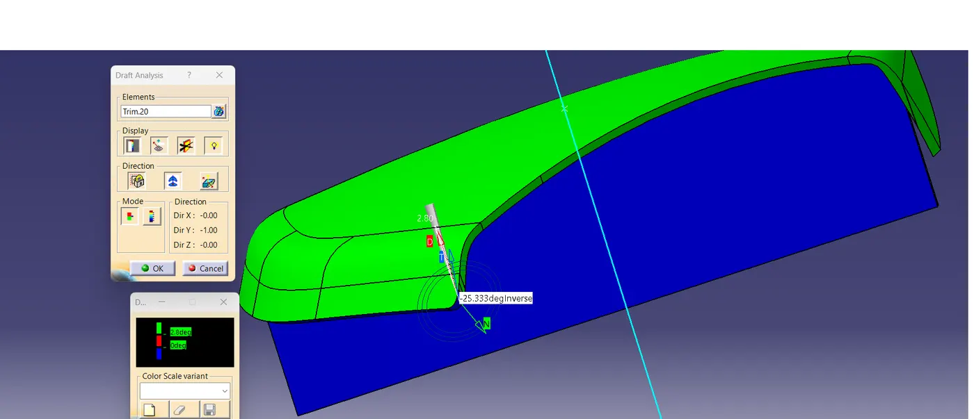
The above image shows less draft due to the surface were created using reference surface method using sweep command , if i create it with the draft direction method it will intersect with the lower substrate part so that i created using reference surface method. The given class A has not enough space for the thickness for both the component.
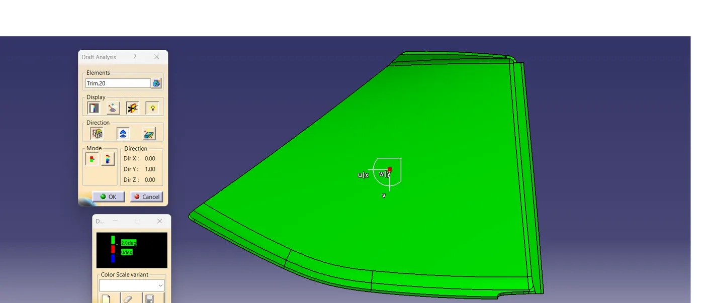
The above class B surface is clearing the draft analysis.
FLANGE CREATION FOR MAP POCKET:-
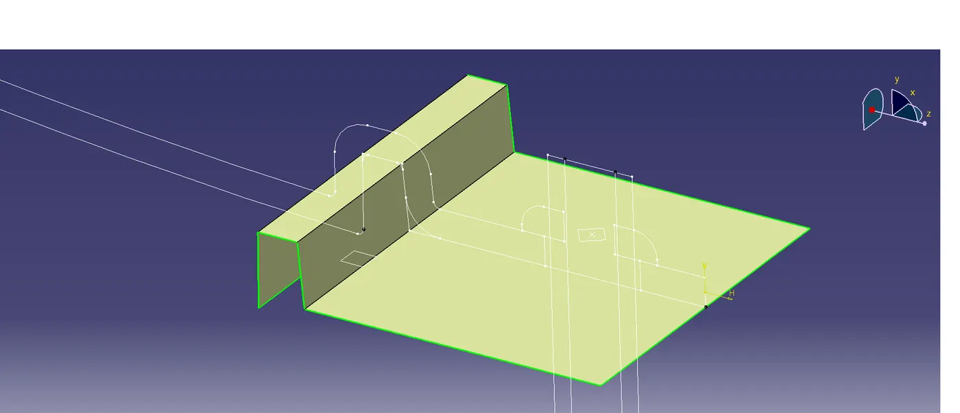
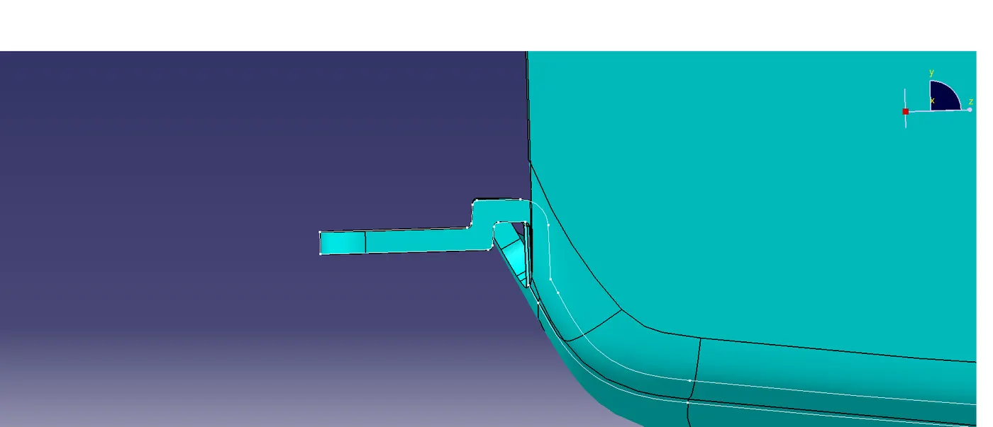
The flanges were created using the master section reference on the map pocket. Then the surface is converted into solid using thicken surface method.
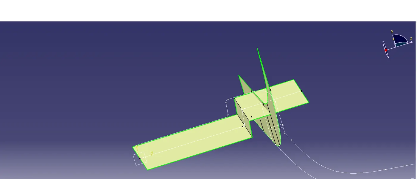
The above image was showing the surface creation for the flange of map pocket, it is located on the other side of the map pocket it is created as per the master section reference and taken multiple extract from the class C surface of the map pocket and created a sketch from the master section
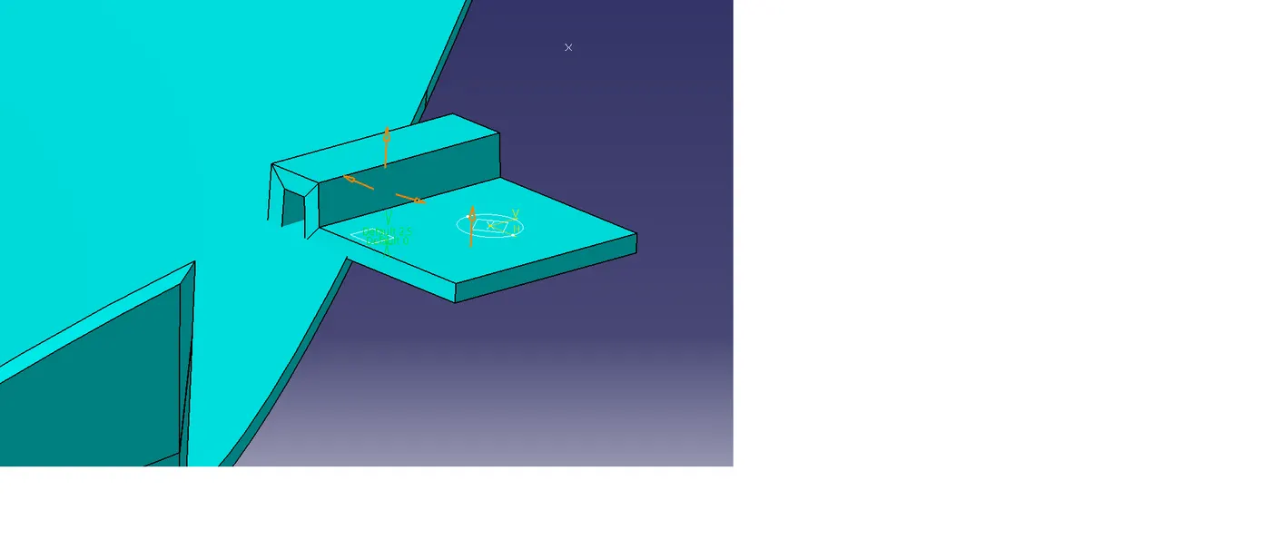
After converting into a solid then rotated the flange along the C surface using rotate option.
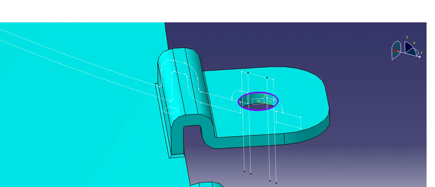
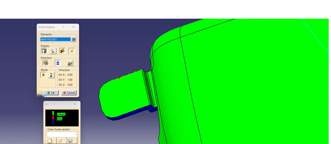
The hole in the flanges was created using the master section reference for heat stakes assembly from the lower substrate. Fillets are given as per the master section reference and draft also given minimum value of 0.5deg. To make more flanges, copied the flange part body and pasted with link for more flanges and translated it to the required area over the map pocket.
DRAFT ANALYSIS OF FLANGE:-
FINAL PART OF MAP POCKET:-
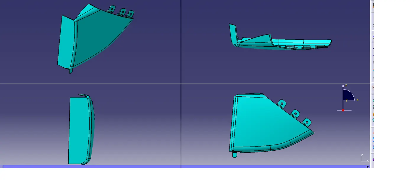
The flages in the master section created on the basis of given master section and own attachment strategy. The smaller flange on the opposite side of the three flanges it has no holes as per the mastersection.
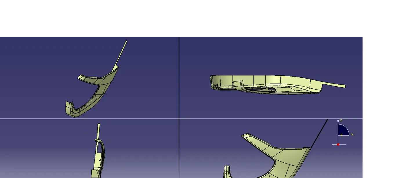
TOOLING AXIS OF CLASS A OF LOWER SUBSTRATE:-
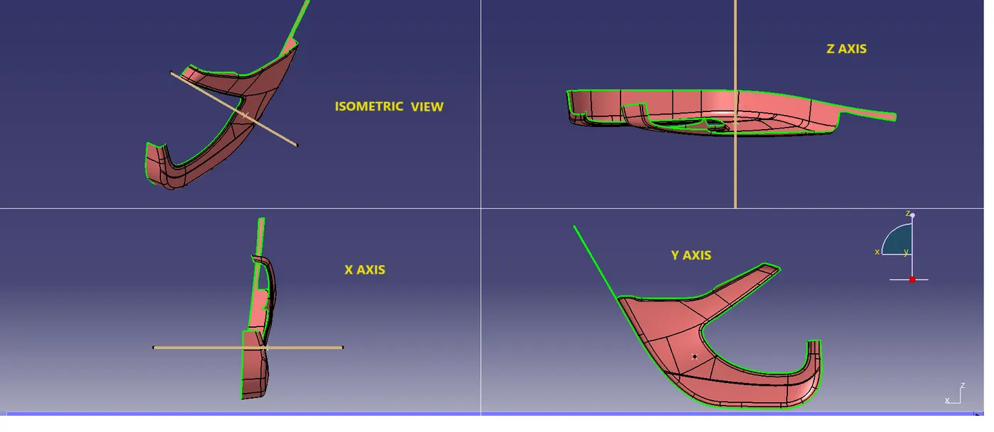
The given input of the class A has no discontinued surface and as we seen the above image the Y axis is feasible for tooling axis. Most of the surfaces are visible along Yaxis tooling direction.
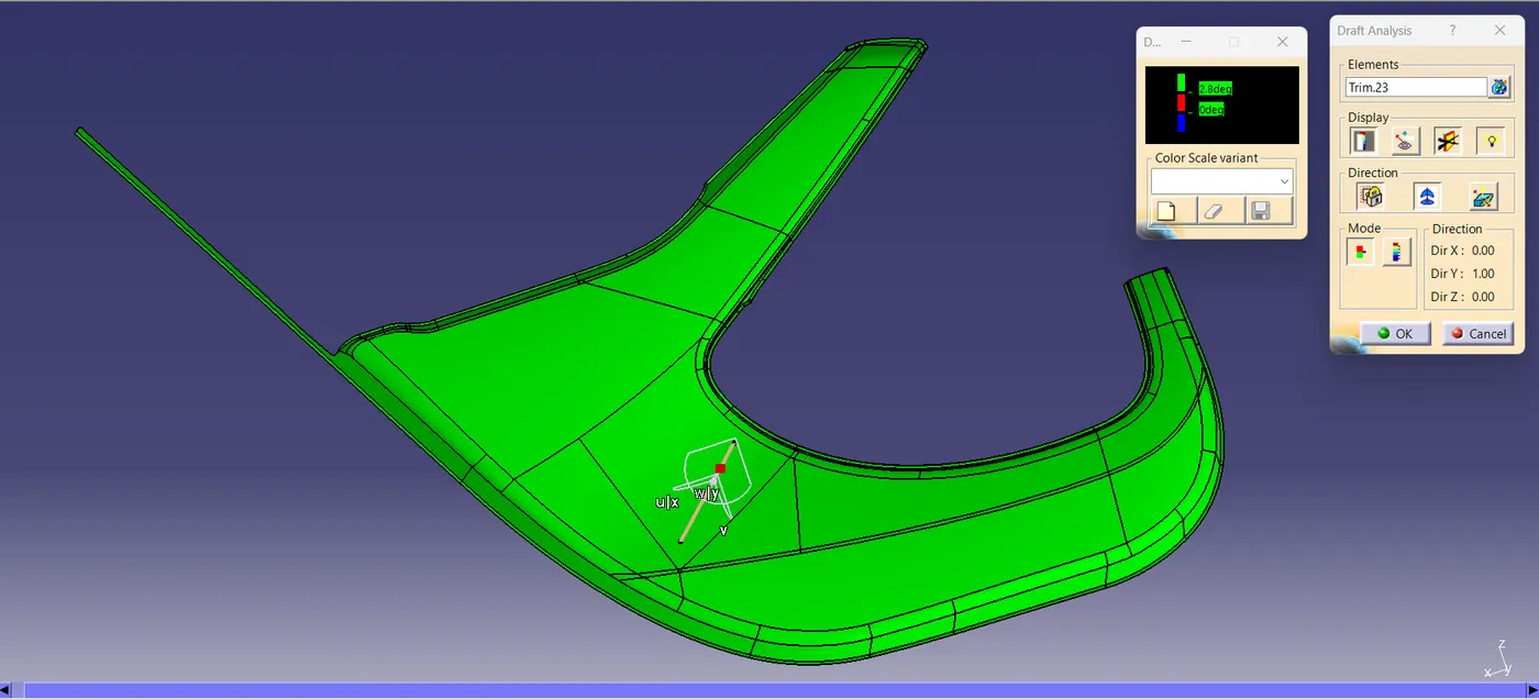
CLASS A DRAFT ANALYSIS:-
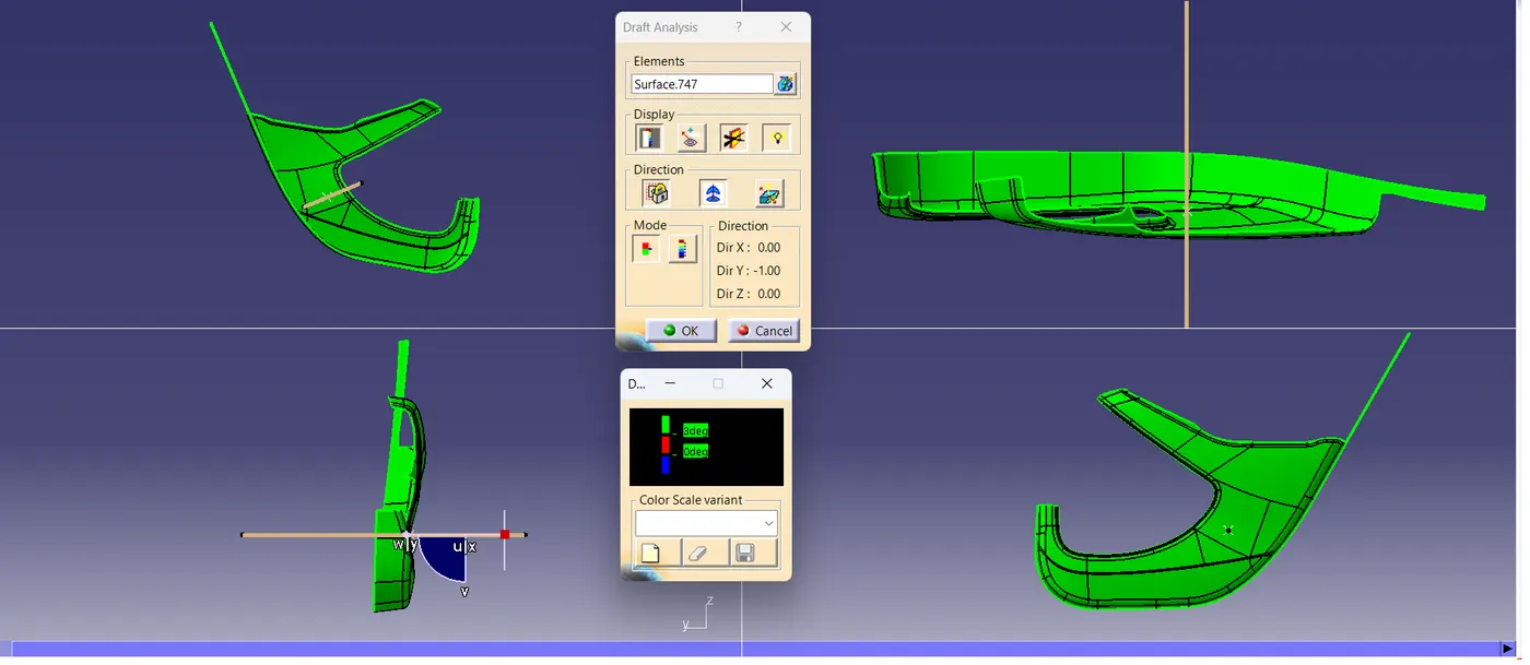
The draft analysis of the given class A of the lower substrate is clearing the draft analysis of 3deg.
CLASS B CREATION:-
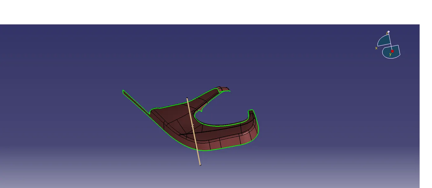
The Class B is created using direct offset method.
CLASS C SURFACE :-
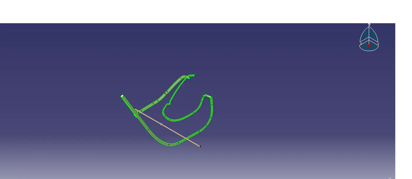
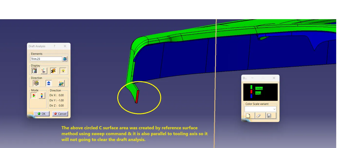
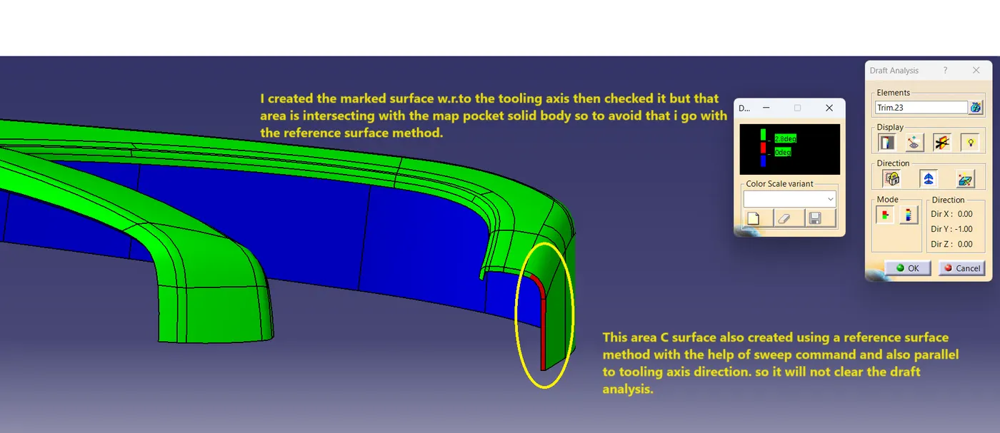
The class C surface is created using both reference surface and draft direction method using sweep command.
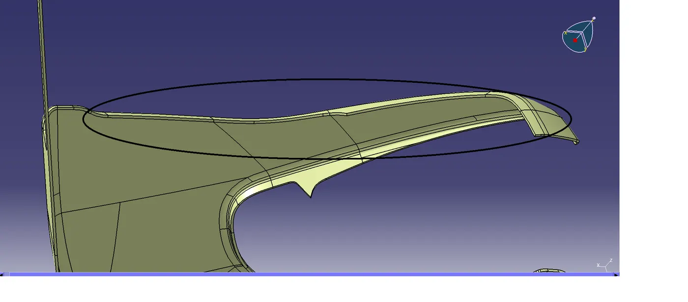
The above marked Csurfaces was created using surface reference method because the Csurface was intersecting with the Arm rest solid body if we create the C surface using draft direction method.
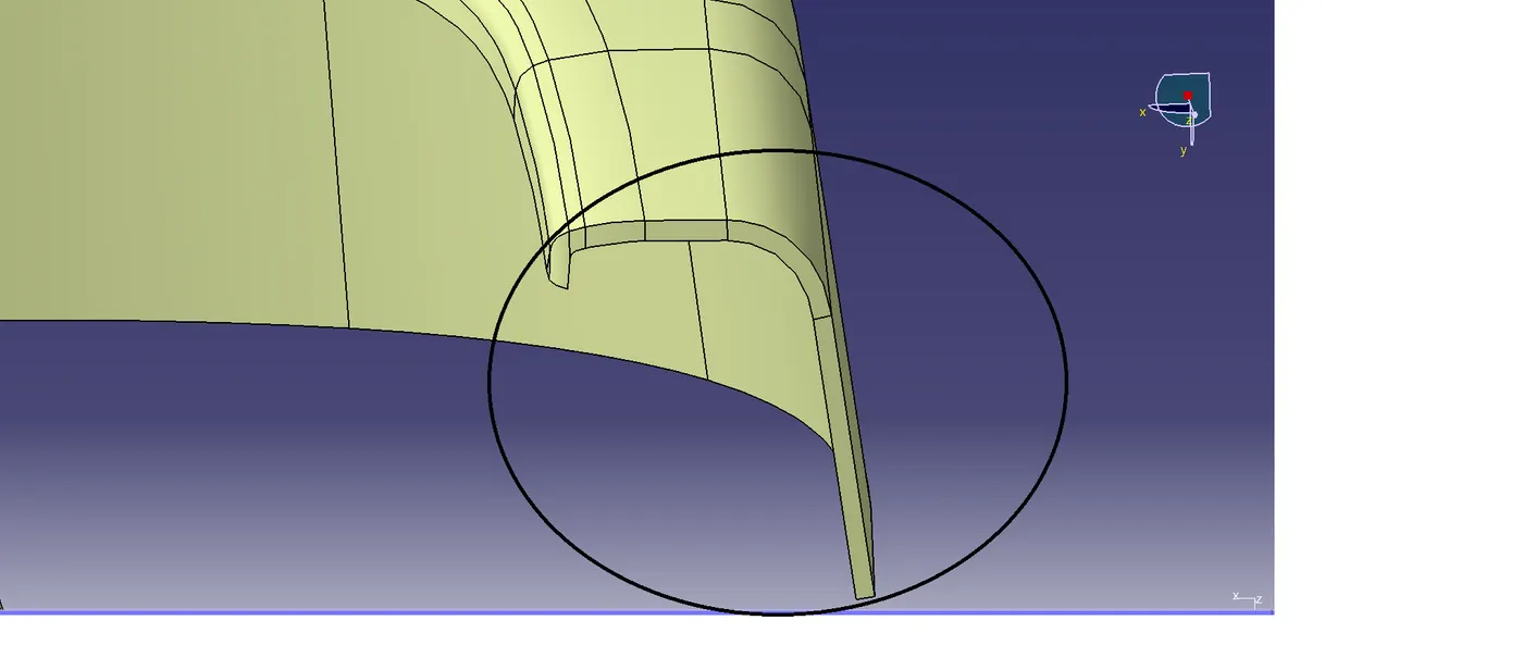
The above mentioned C surface is created using both the reference surface and draft direction method due to avoid the intersection with the Map pocket area.
CLOSED SURFACE OF LOWER SUBSTRATE :-
DRAFT ANALYSIS OF LOWER SUBSTRATE: -
The above image is the Draft analysis of Class B surface of lower substrate.
HEAT STAKES:-
Heat staking is a process which utilizes pulsed heat to join two or more parts together where at least one part is made out of plastic. It works by heating a plastic part to just above the glass transition temperature while simultaneously applying force so that it is deformed. The part is then cooled (still under force) to complete the process.
Heat staking also known as thermoplastic staking is the process of joining two dissimilar materials together. In heat staking we use local heating and cooling to raise the temperature of plastic components and allow plastic reforming to be carried out. This reforming can be used in a wide variety of applications.
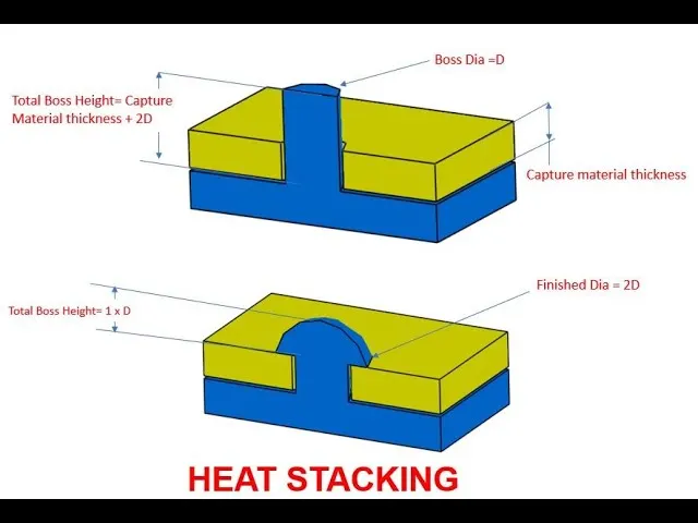
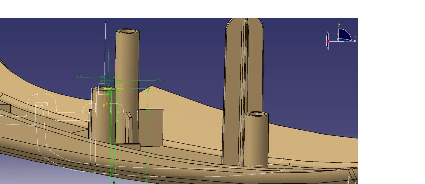
For creating the heat stakes the given mastersection reference is used and created a sketch and using revolve command created a solid body of heat stake. Translated the heatstakes using translate command to the required places as per the assembly strategy.
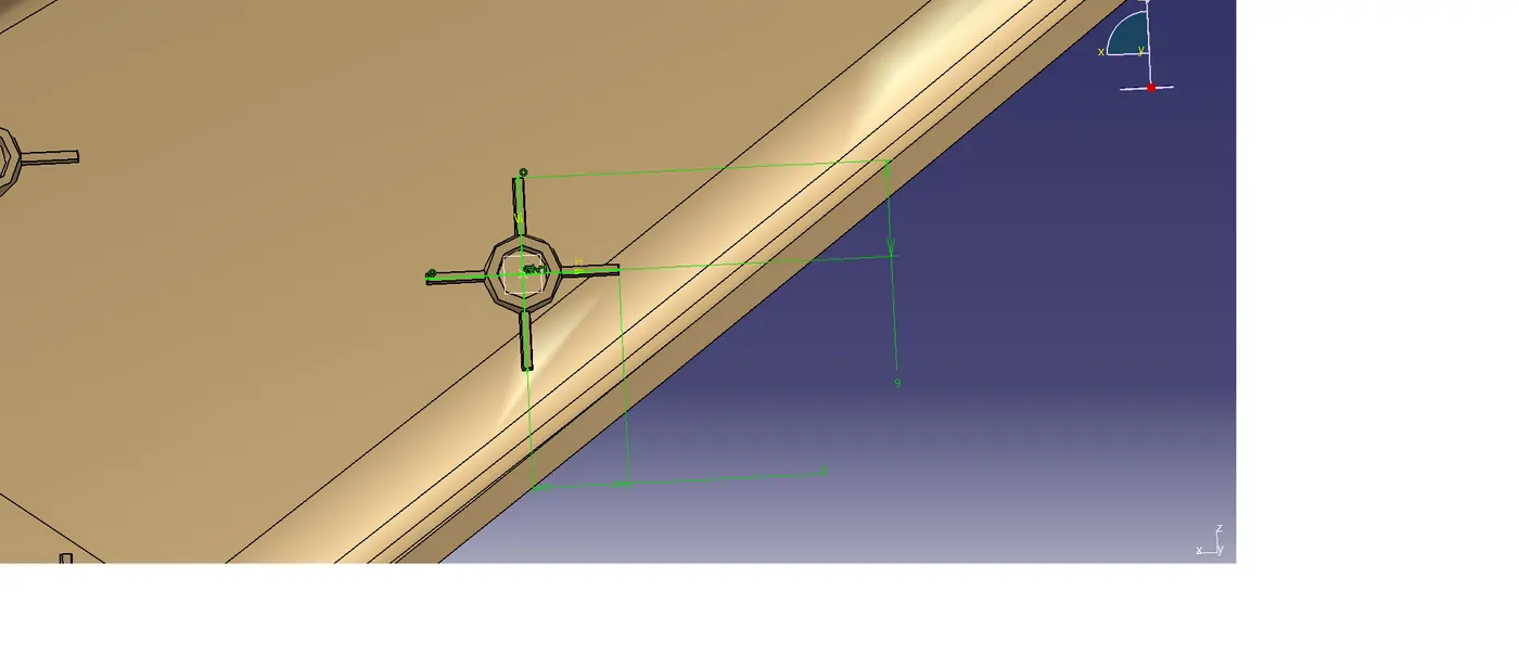
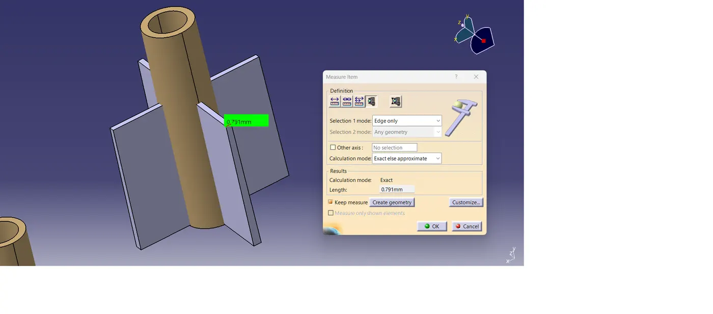
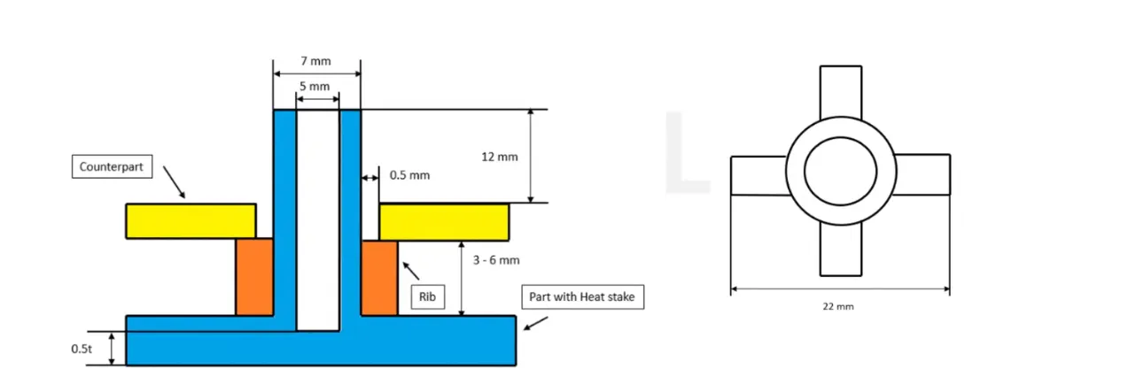
The ribs are created as per the guidliness, due to the given model height and length was changed according to the attachment strategy and drafted 0.5deg.
FOUR WAY LOCATERS:-
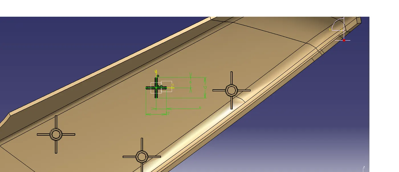
To arrest the degrees of freedom of a component locaters are used there are two types of locaters 2way & 4way locaters here i used 4way locaters to arrest the components.
The rib rule is followed to create the fourway locaters due to the height of the locaters after giving the 0.5draft value edge tip thickness were less with respect to the rib rule so after discussed with the TSE, increased the thickness accordingly .
DOG HOUSE :-
The Doghouse is also an engineering feauture used for attachment strategy especially in fixation of pushclips and other components.
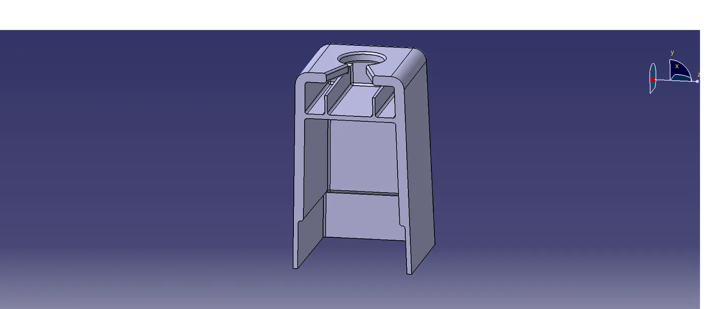
The doghouse was created with the help of reference image taken from the A pillar mastersection project and adjusted with respect to the push clip fixation as per the attachment strategy.
PUSH CLIP:-
The push clips may seem like small and insignificant components in a vehicle, but they play an important role in automotive engineering. These small and often overlooked plastic clips are used to secure various parts of a car together, such as the door panels, dashboards, and trim pieces.
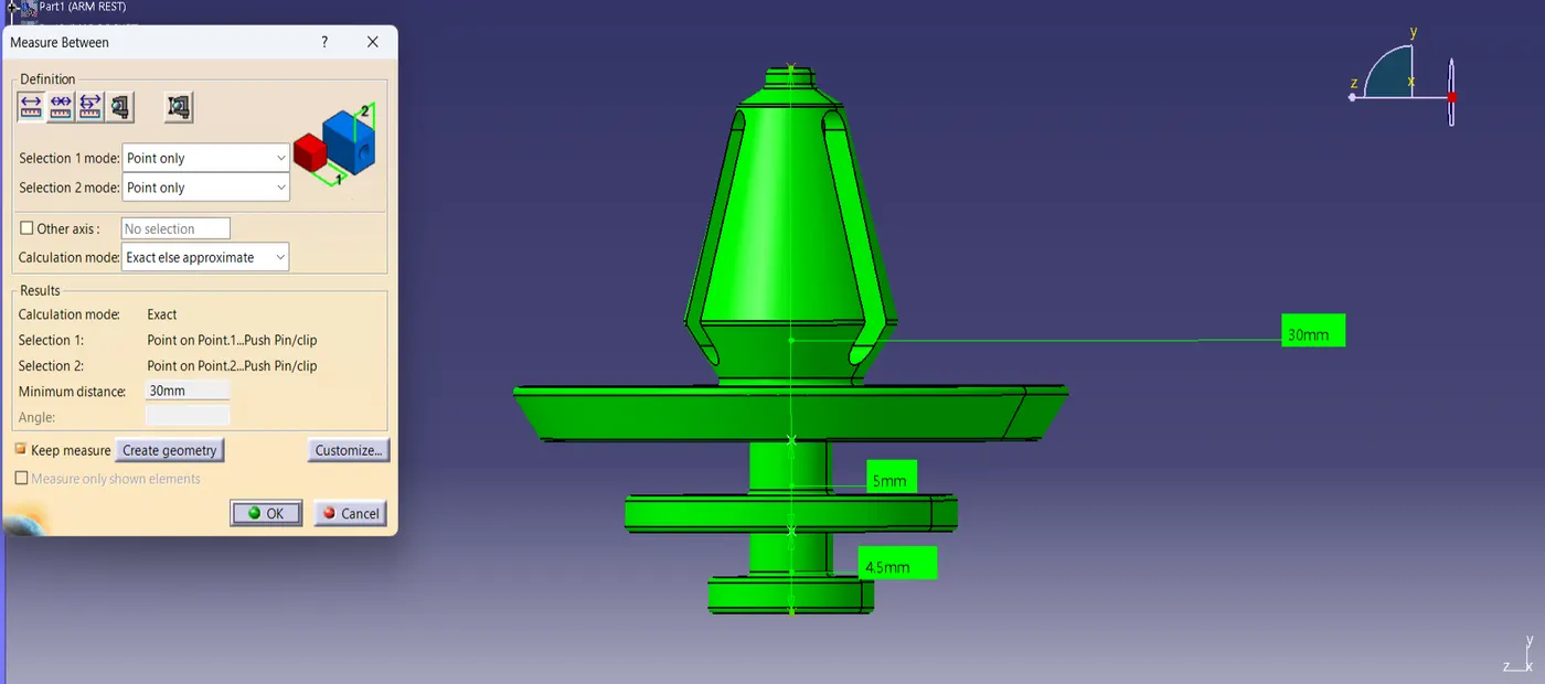
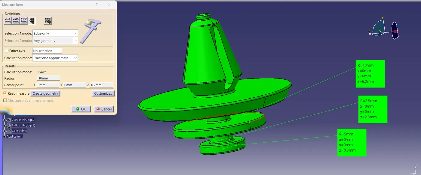
According to the measurments of the push clips Doghouse was created & modified as per the attachment strategy.
DRAFT ANALYSIS OF ENGINEERING FEAUTURES IN LOWER SUBSTRATE:-
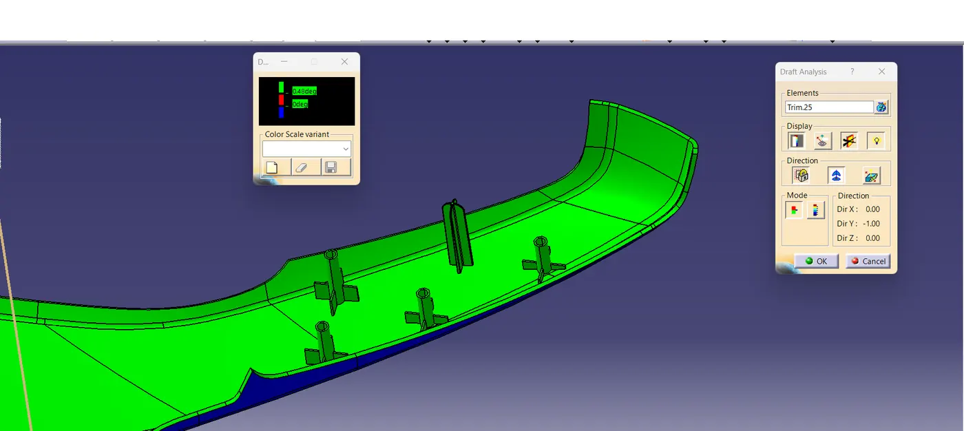
All the engineering features has minimum draft of 0.5deg.
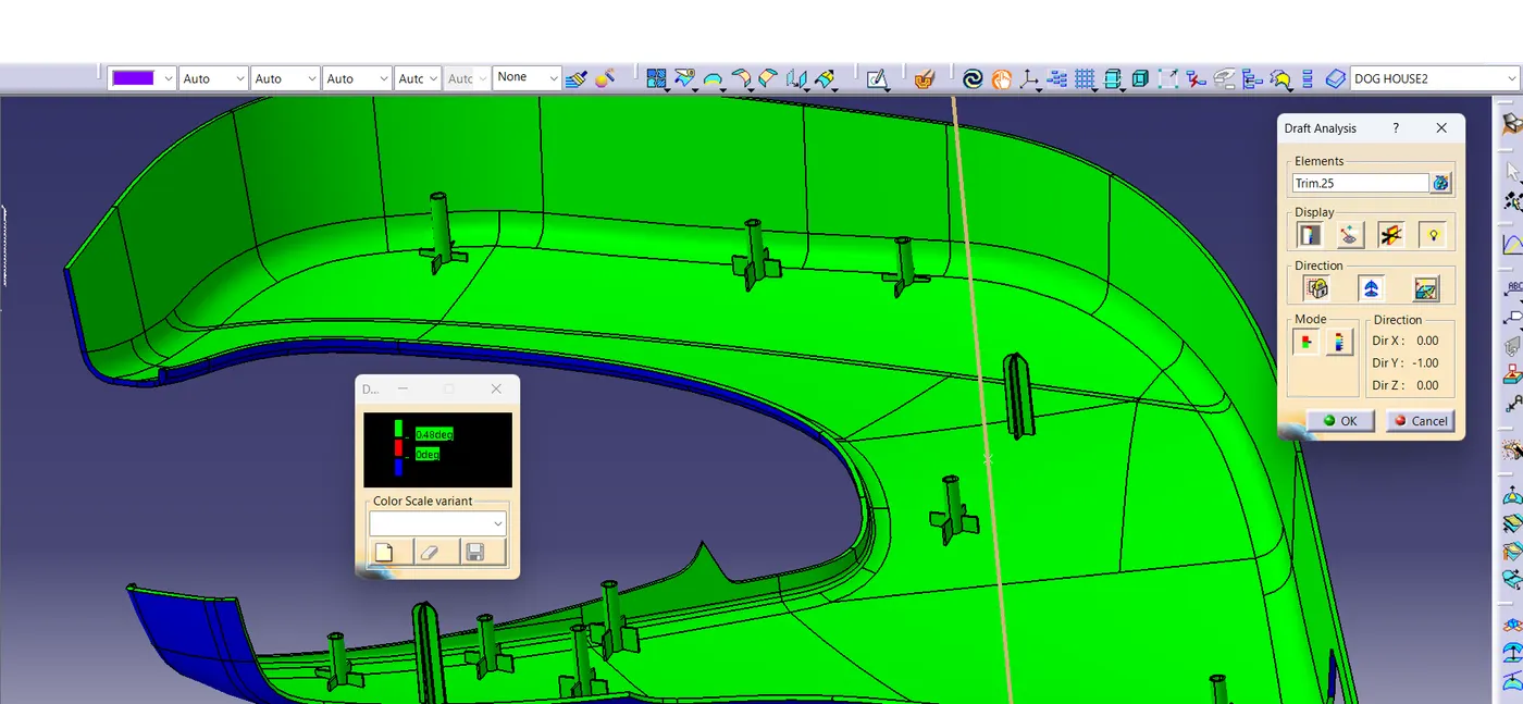
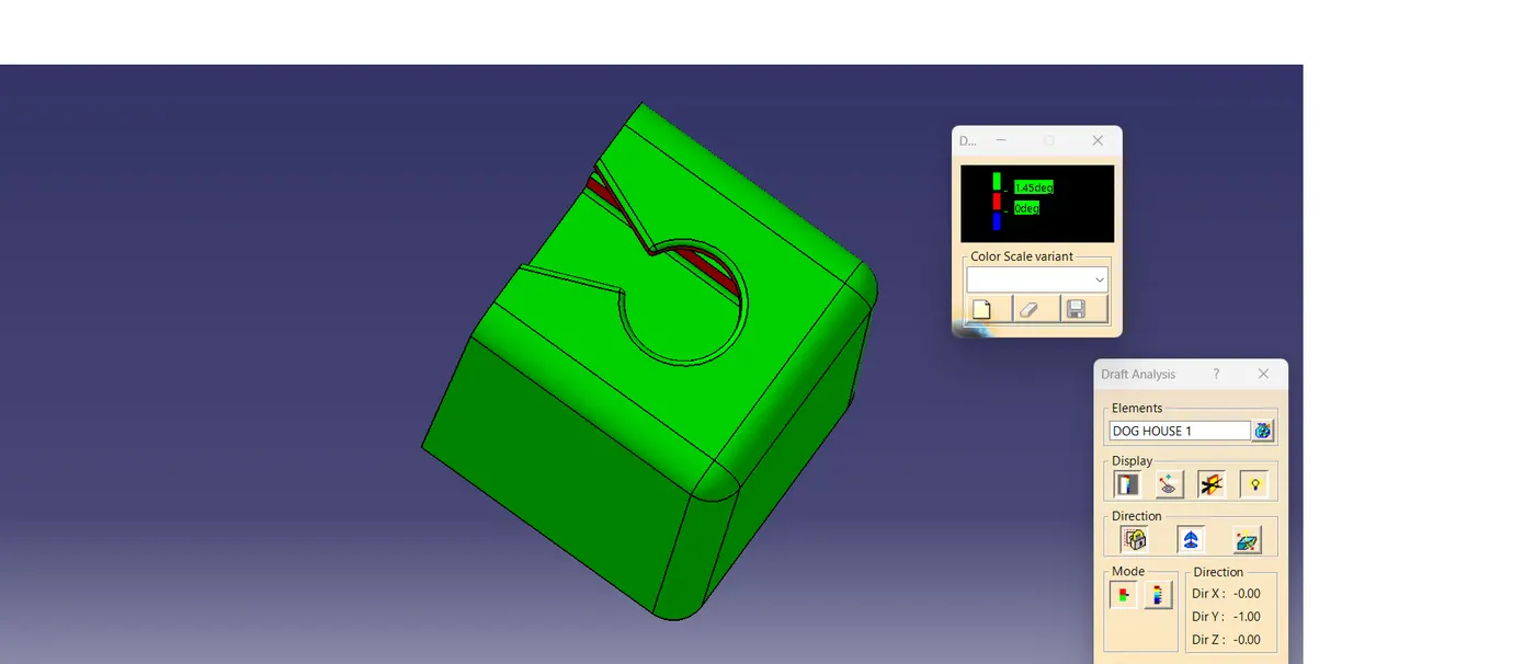
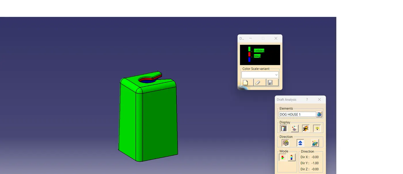
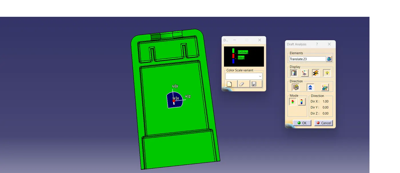
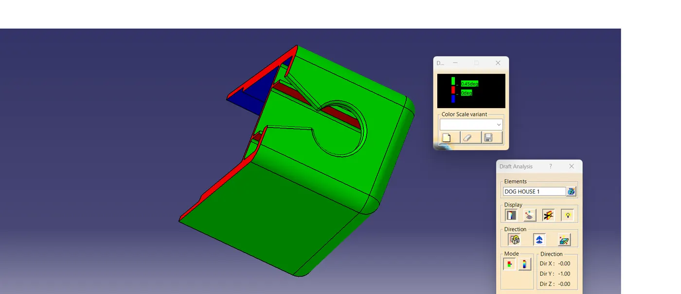
The Doghouse outside area was drafted 1.5 deg as per the standards.
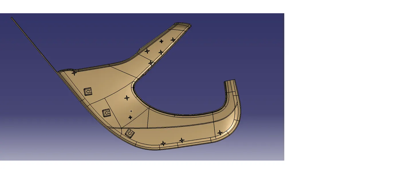
FINAL PART BODY :-
CLASS A OF BOTTLE HOLDER :-
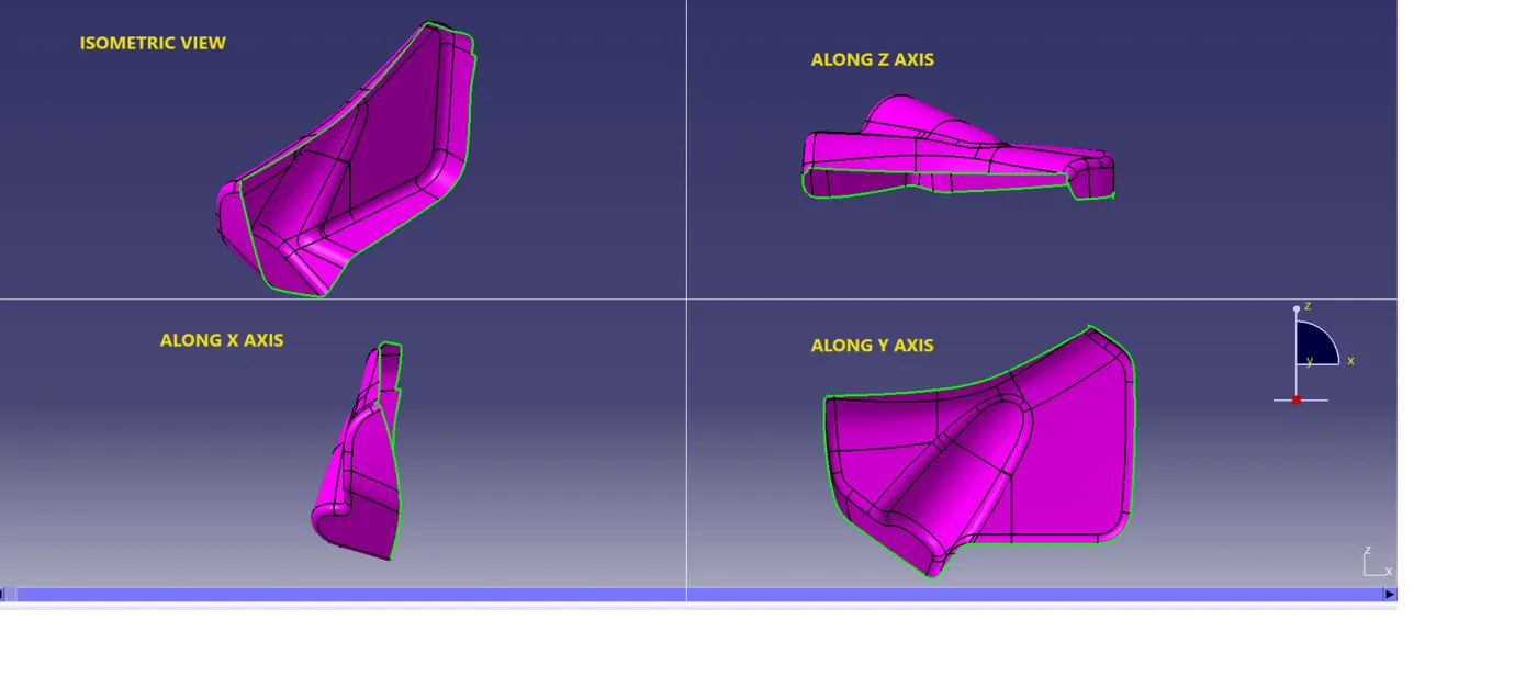
As we see from the above image the y axis direction is feasible for tooling axis because most of the surfaces are visible along y direction.
DRAFT ANALYSIS OF CLASS A:-
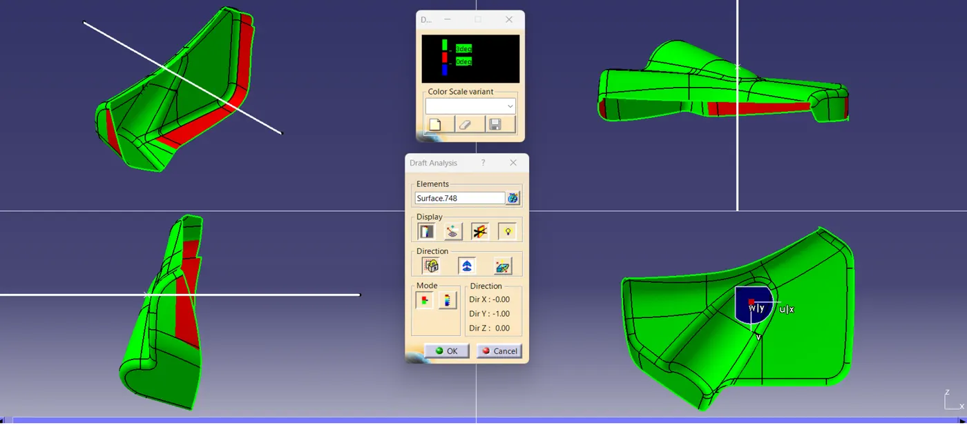
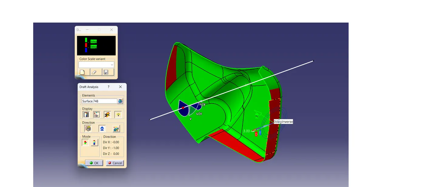
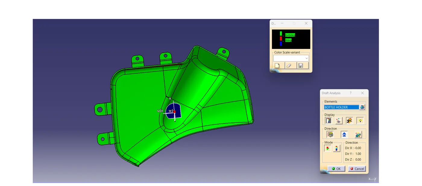
Some of the areas having straight surface which is parallel to the tooling axis. so it will not clear the nominal draft of 3deg unless or untill modified by Styling team.
CLASS B SURFACE :-
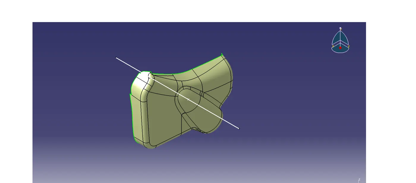
The class B surface was created by using the direct offset method with 2.5mm refered from the given mastersection. The surfaces which is not cleared the draft analysis in class A will not going to clear in class B also.
CLASS C SURFACE:-
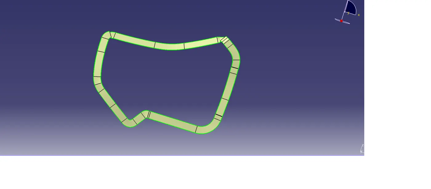
The class C surface was created by reference surface method using sweep command so that the C surface intersects with the class B surface and forms a closed surface .
CLOSED SURFACE OF BOTTLE HOLDER:-
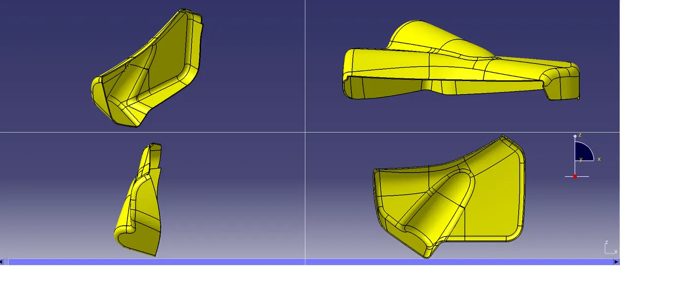
DRAFT ANALYSIS OF BOTTLE HOLDER:-
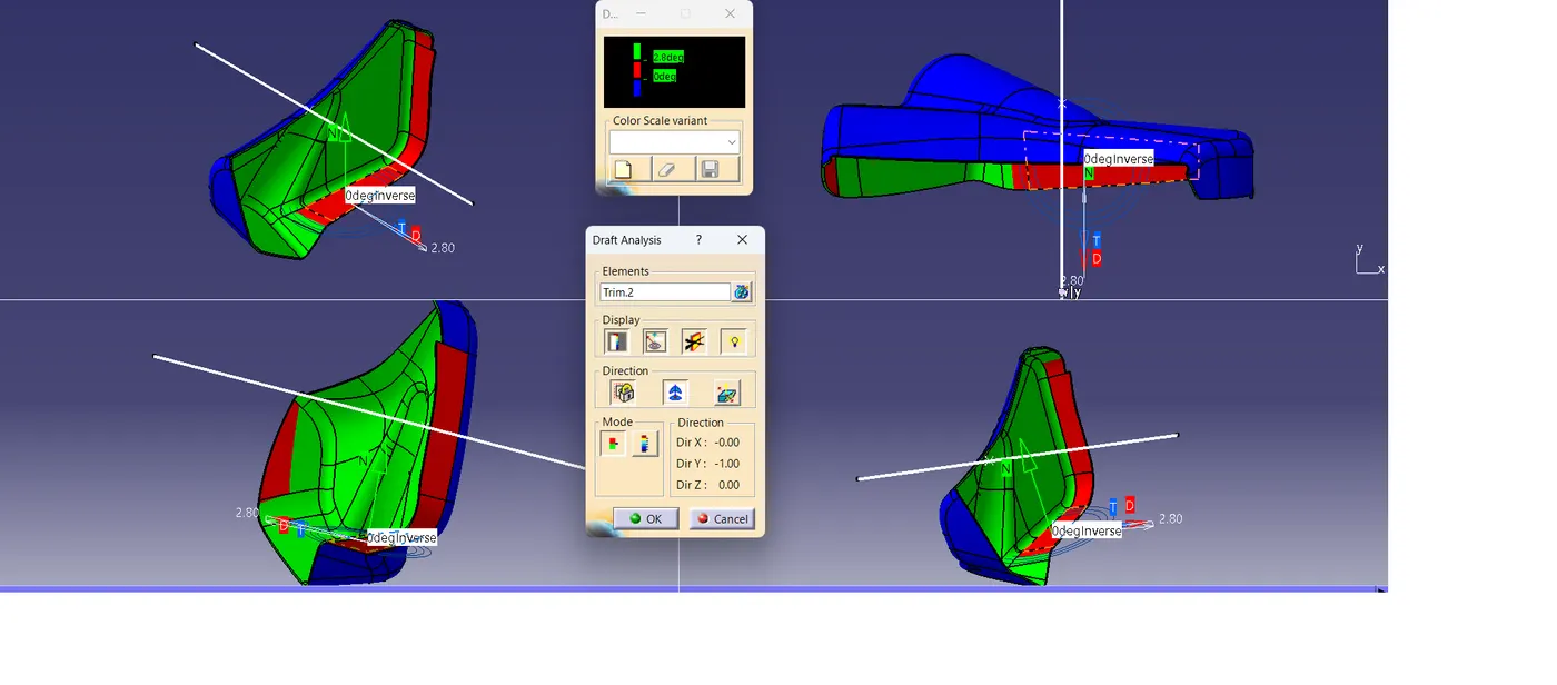
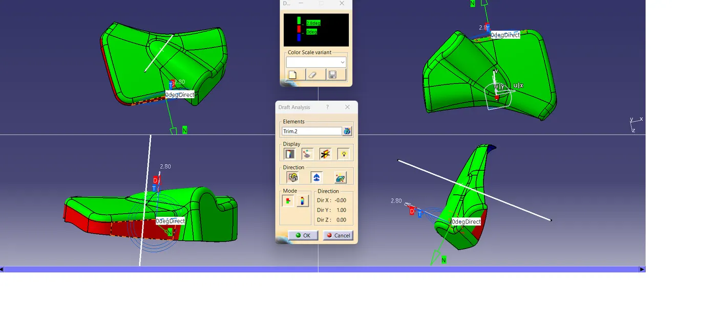
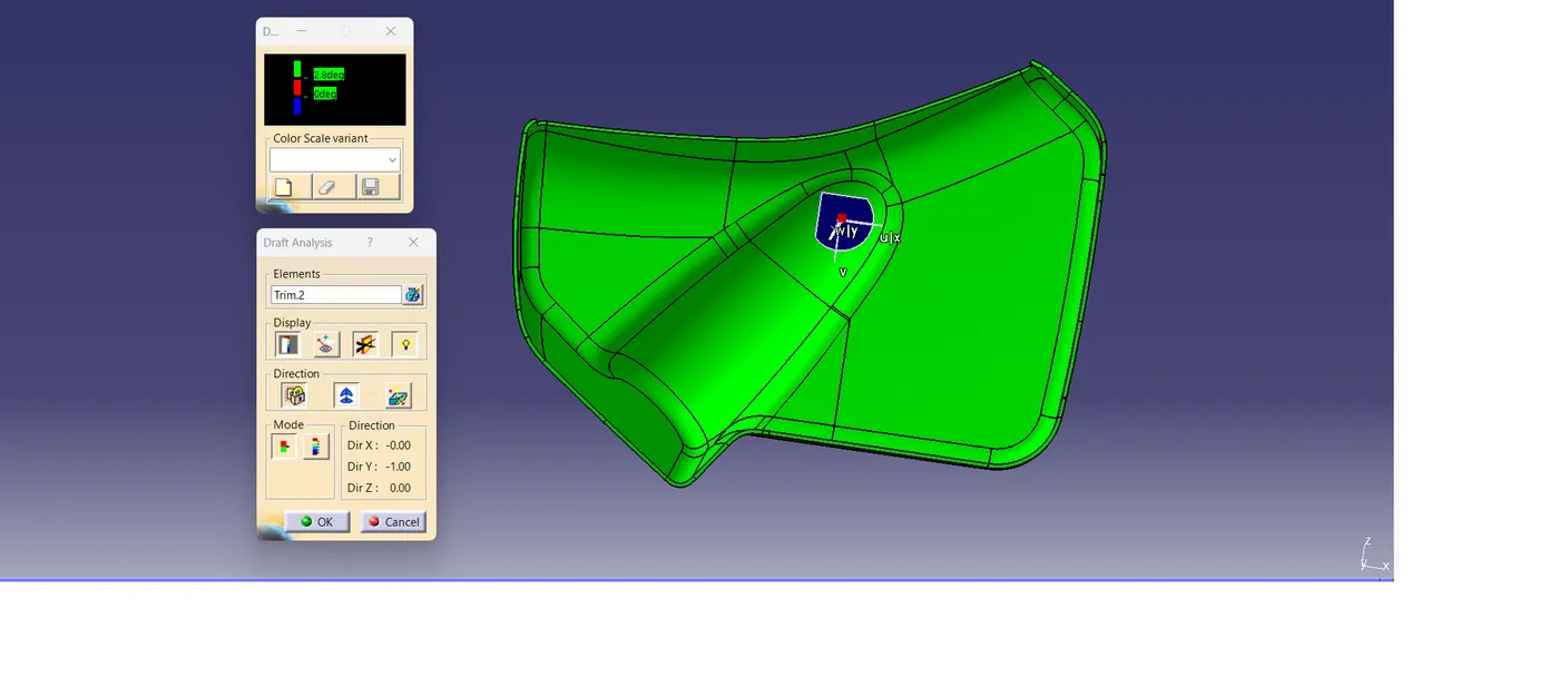
The given class A is not having the draft of 3deg in some areas as we seen them above so it is reflected over class B side, by the same sides of Class B is not clearing the draft analysis. The class C surface was created using reference surface method.
FLANGES : -
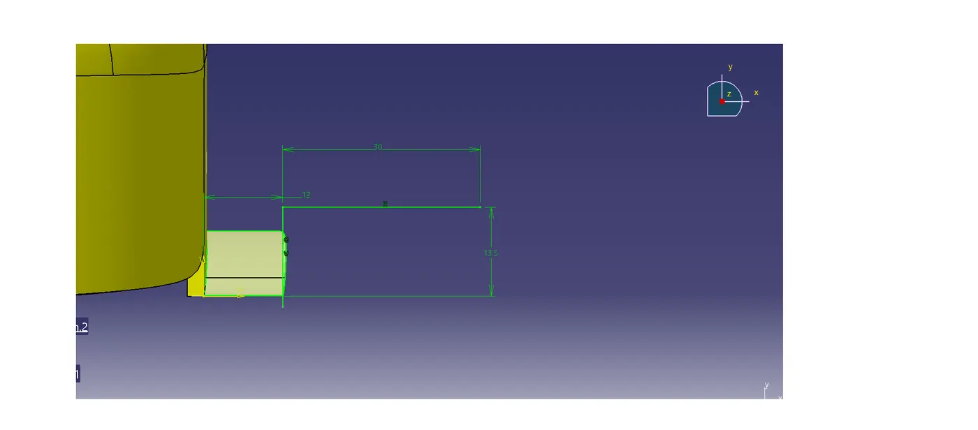
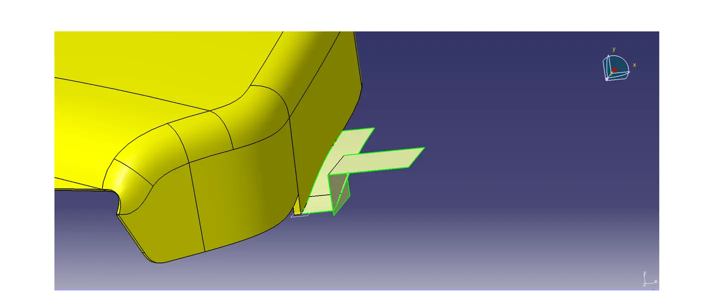
The flange was created using extract from the C surfaces edges of the bottle holder and created a constrained sketch for the upper portion of the flange and extruded it along the Z direction and made a trim to create a flange surface.
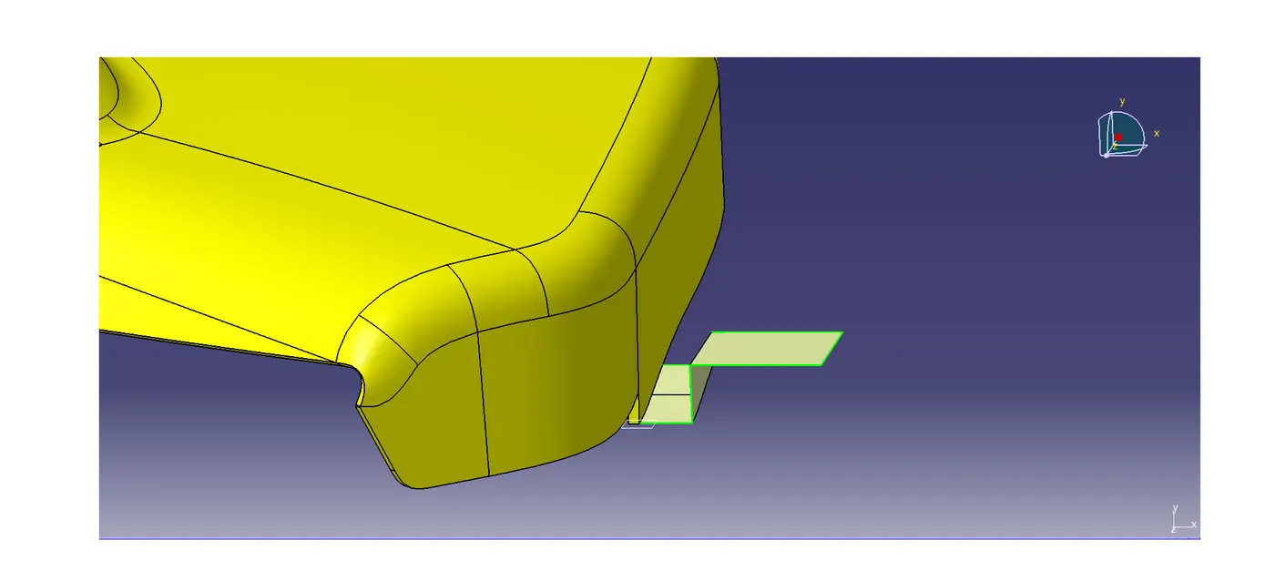
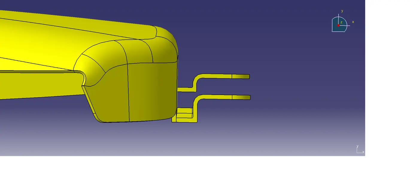
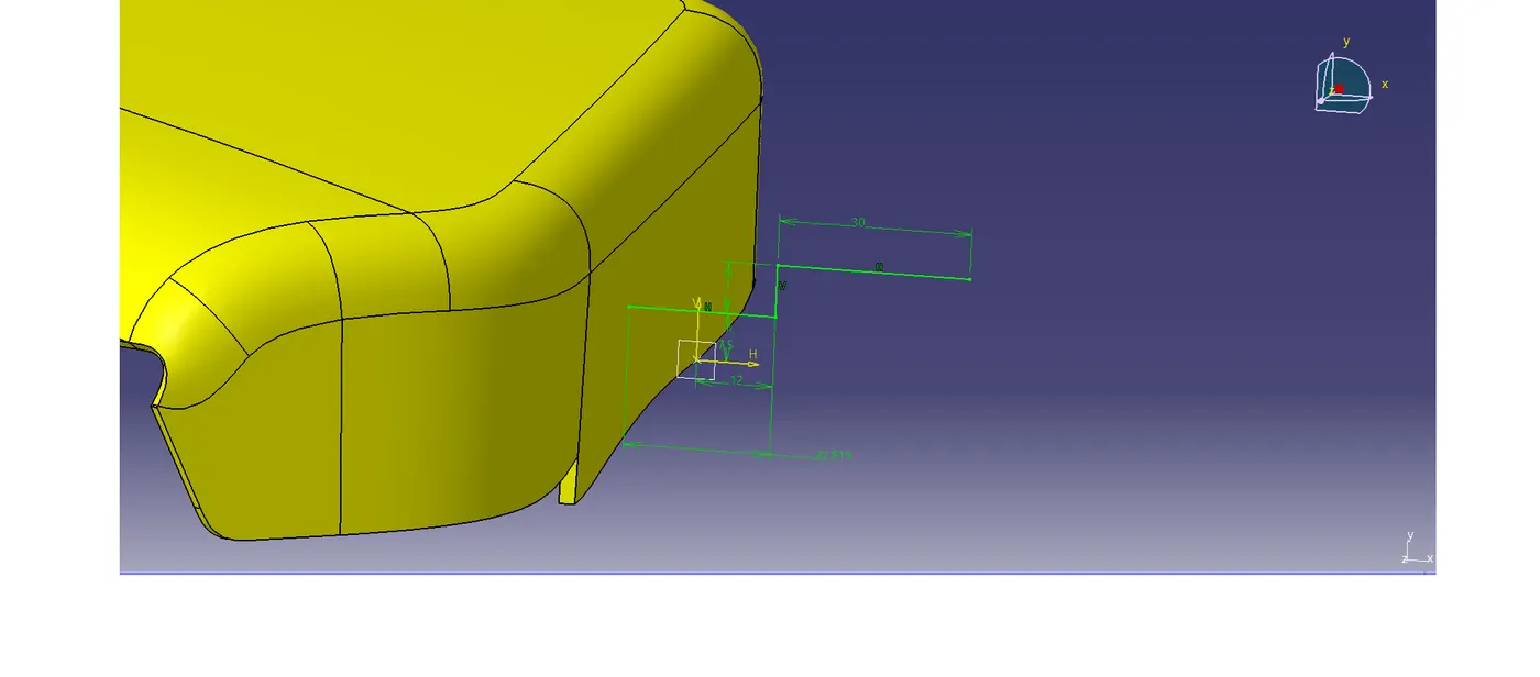
By using thicken command created a solid flange and the second flange is created using the same method, created a constraint sketch and extruded it and make the created surface using thicken surface command.
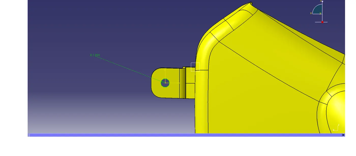
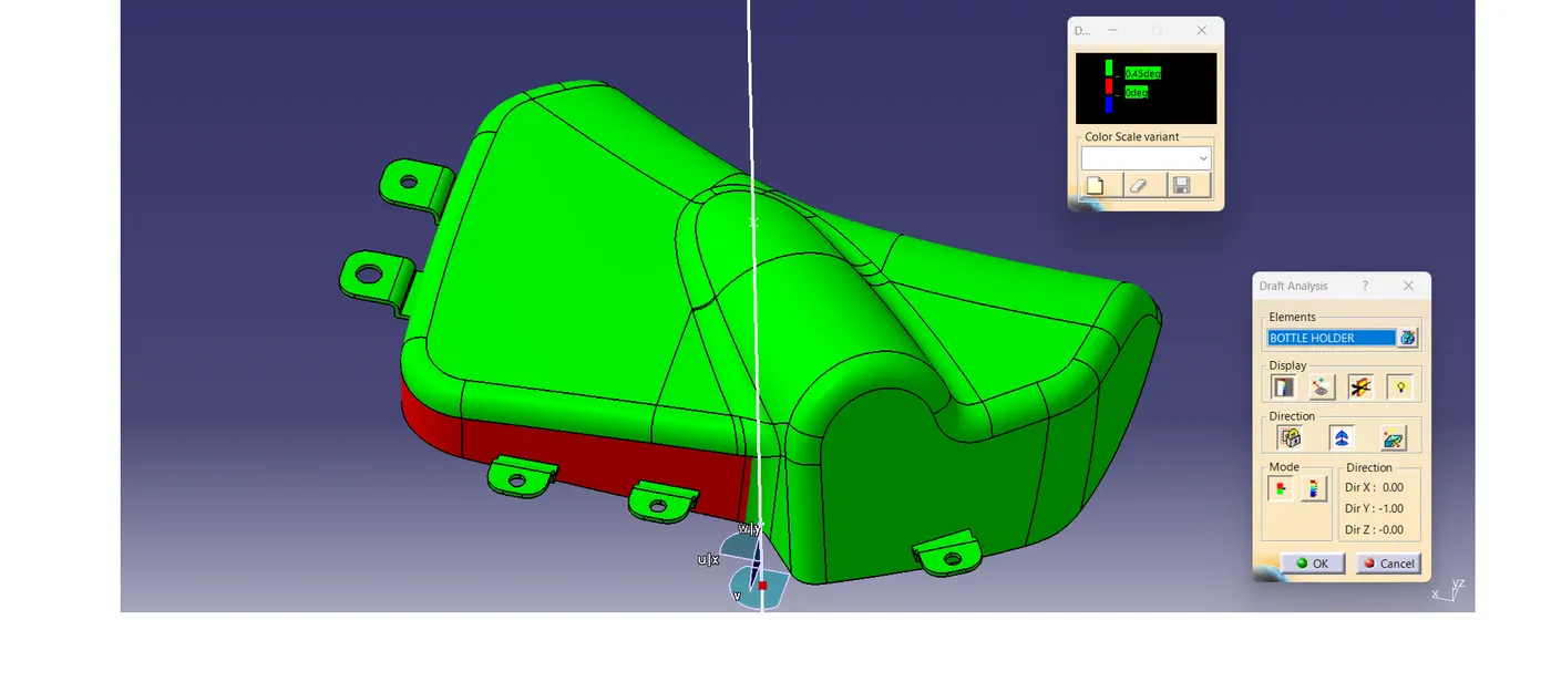
After the creation of the flanges drafted value of 0.5deg and filleted the edges.
For heat stakes and four way locaters created a hole cutout for the attachment strategy and drafted it with the value of 0.5 deg.
DRAFT ANALYSIS OF FLANGES: -
ASSEMBLY OF DOOR TRIM PANEL:-
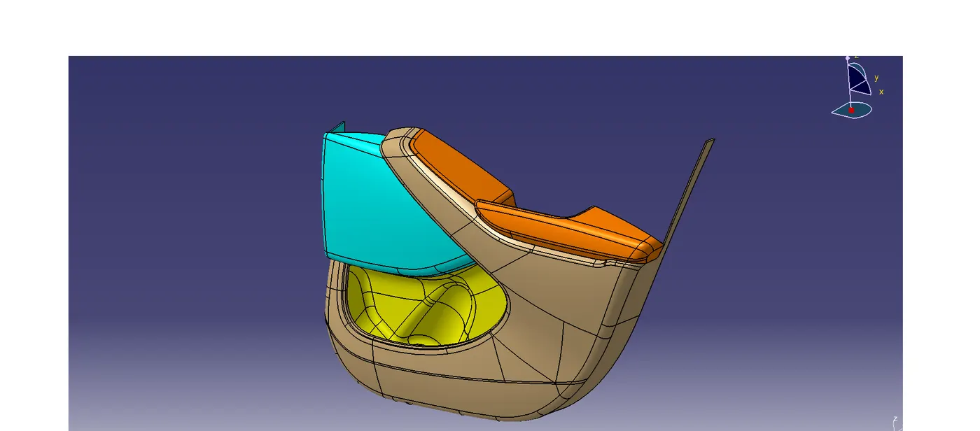
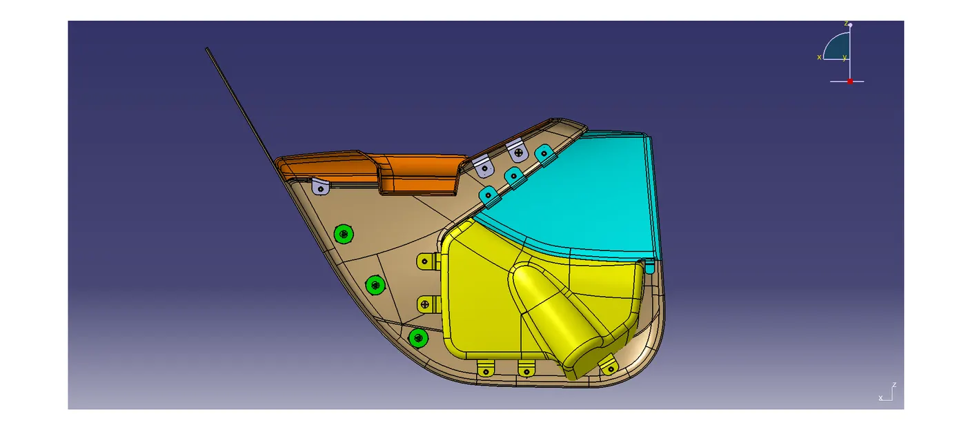
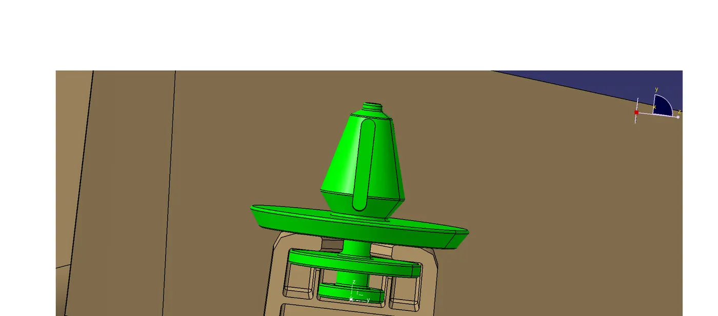
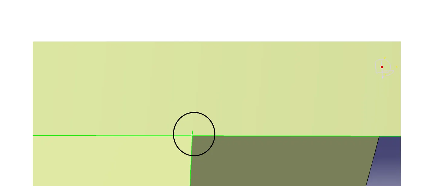
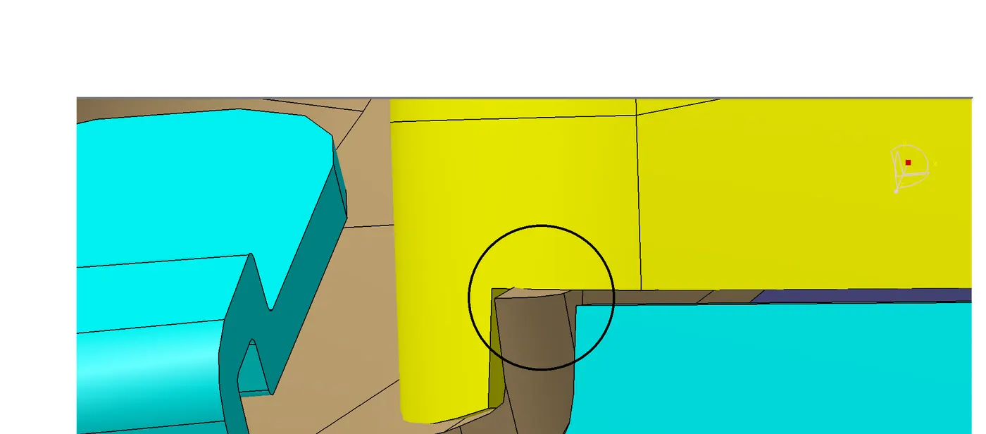
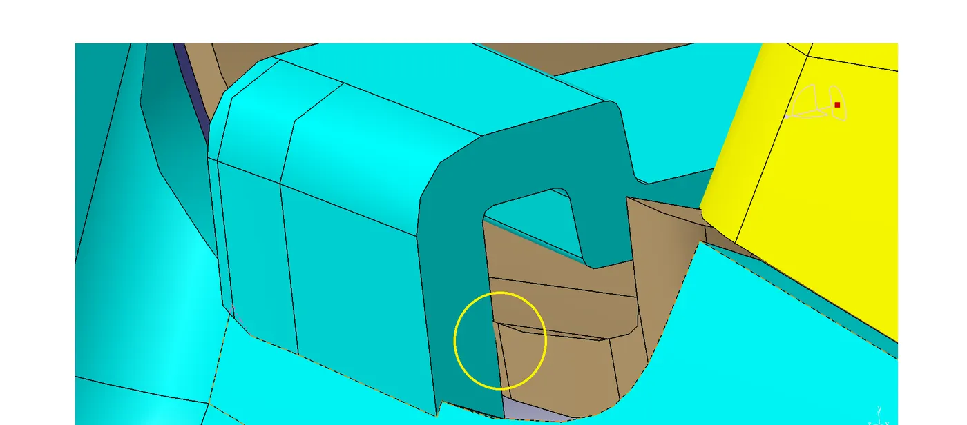
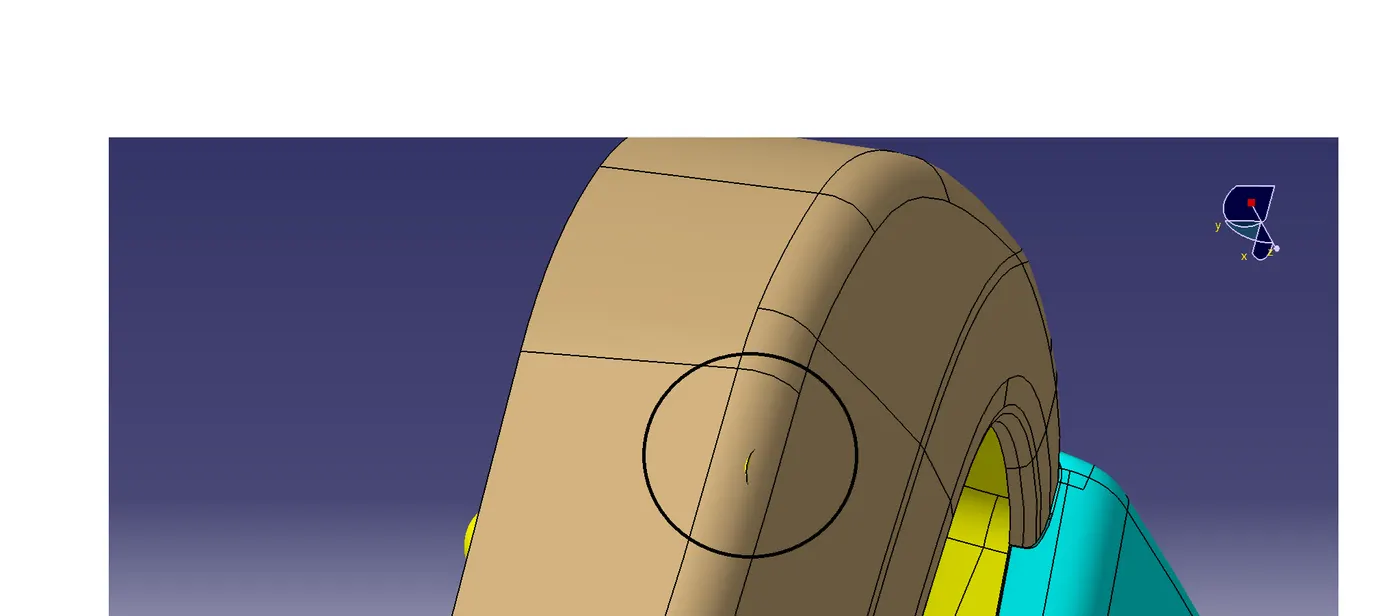
In some parts , specific areas are intersecting with other components due to the given class A surface ,to avoid this it should be reported to the Class A styling team to do the required modifications.