Week 12- Final project
DOOR TRIM PANEL DEVELOPMENT
AIM:
- To design the CAD model Door trim panel from the given class A surfaces of all the components.
- The Thickness of the part should be maintain as per given master section.
- Creation of B side engineering features by referring master section.
- Creation of Tooling axis to perform the draft analysis on a closed volume final component as well as on engineering features.
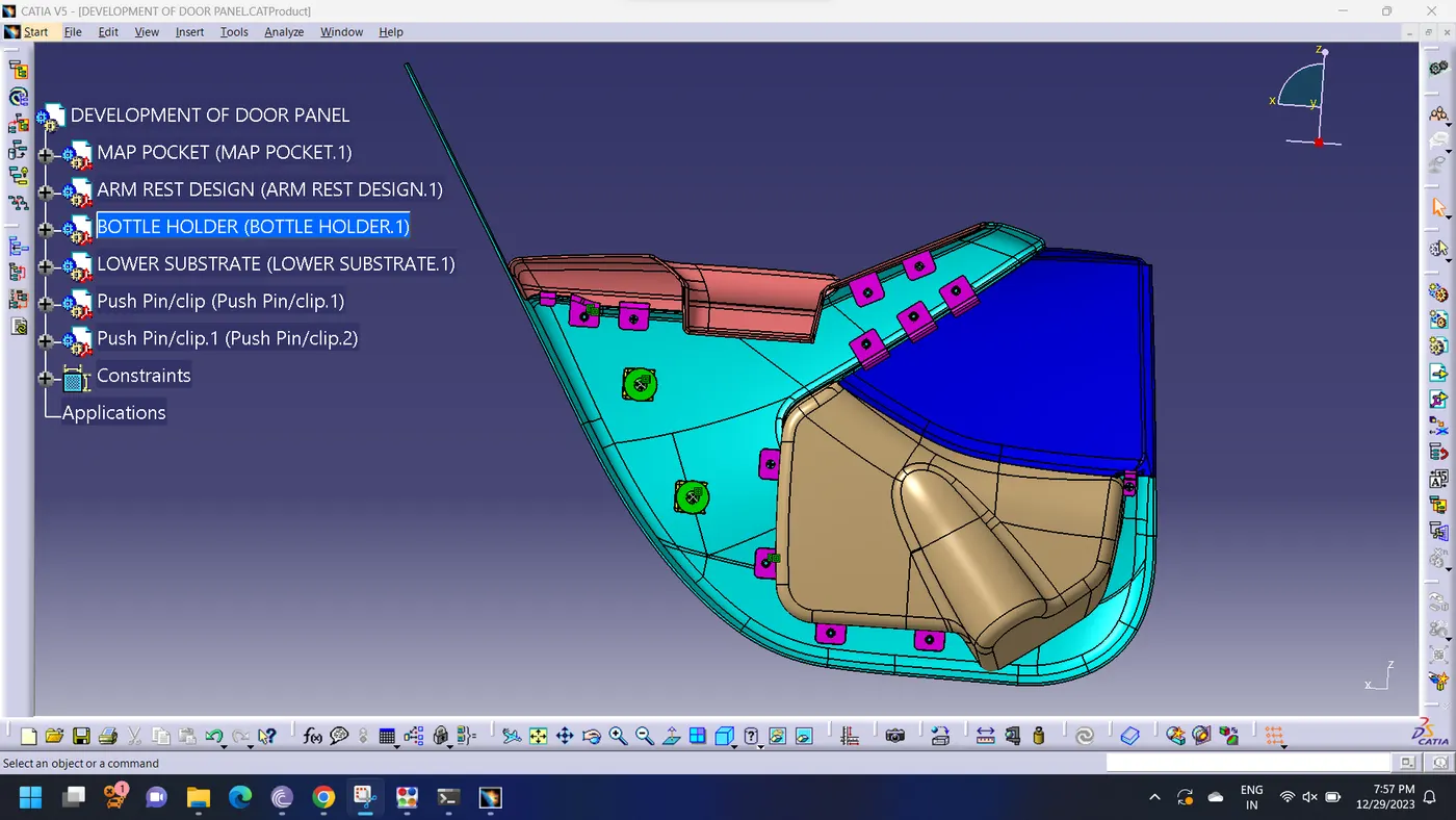
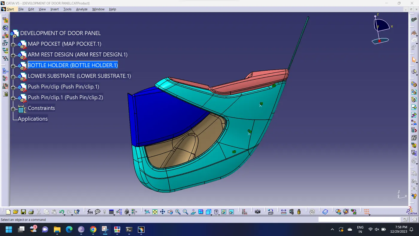
- Assembly of all the components involved in the door panel along with their lower attachment features.
OBJECTIVE:
The project deals with the explanation of method followed to develop door trim inner panel. In this with the given Class-A surface, Class-B surface and Class-C surface were created along with the tooling axis. Other attachment features were also created for assembly of the different components of door trim.
INTRODUCTION:
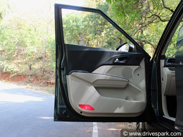
The inner door panel is an aesthetic and functional component in a car, it is the interface between the car interior and the inner working of door. Inner door panel usually consists of armrest, map pocket, bottle holder, handle bar, other switches, upper and lower substrate, storage compartments, convenience (puddle) lights and locking mechanism. Nowdays door panel is made of plastic MTL like polypropylene, ABS etc. which helps in making lightweight and complicated shapes of door panels.
The manufacuring Process of plastic door panel is called Injection molding. In this manufacturing process the heated molten plastic material is injected into the mould between core and cavity and cooled down to form a solid plastic component.
PROCEDURE:
Given CLASS-A surface with Mastersection
Components included in door panel
- Map pocket
- Bottle holder
- Lower substrate
- Armrest
MAP POCKET DESIGN
Class-A surface of Map Pocket
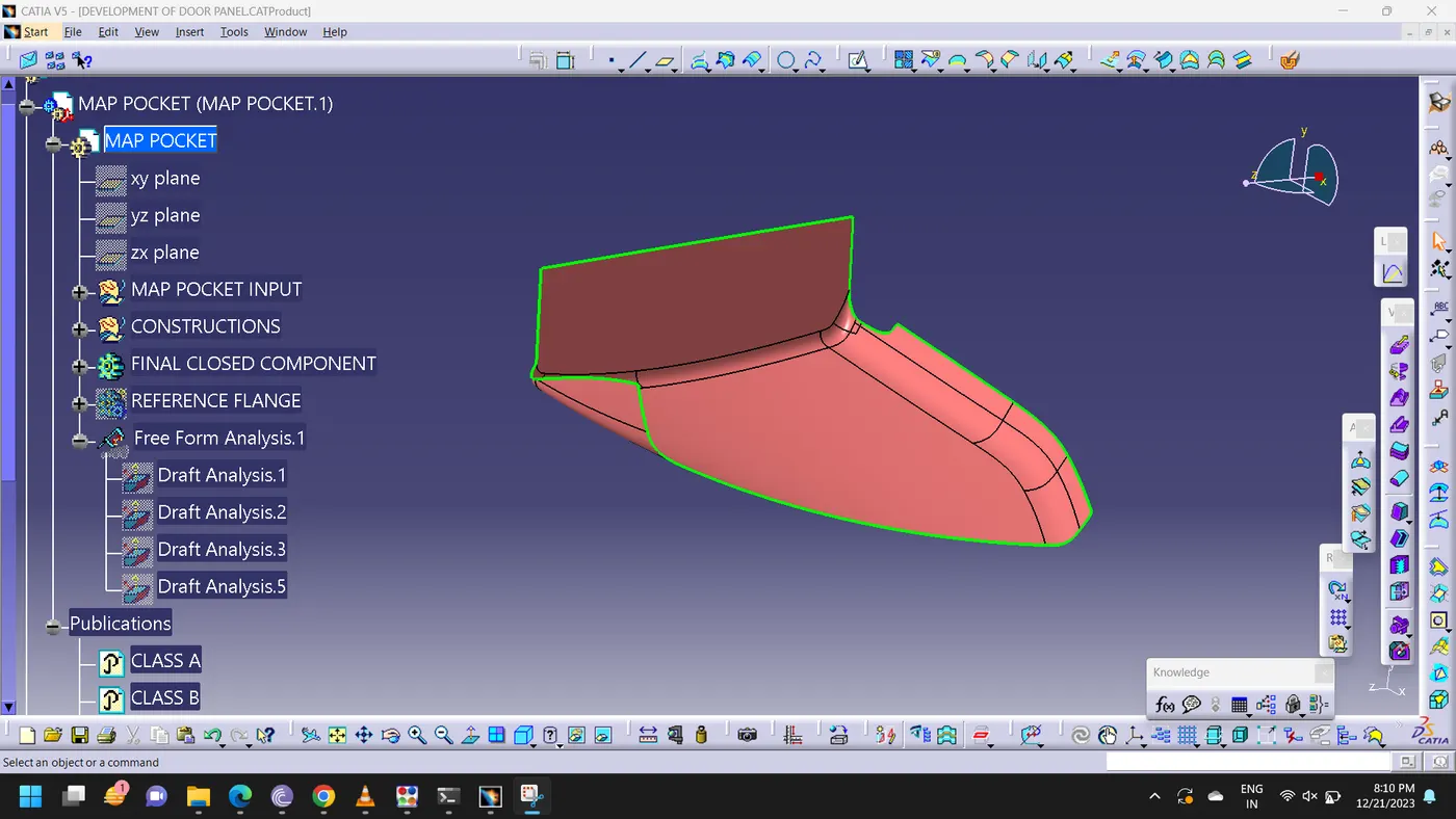
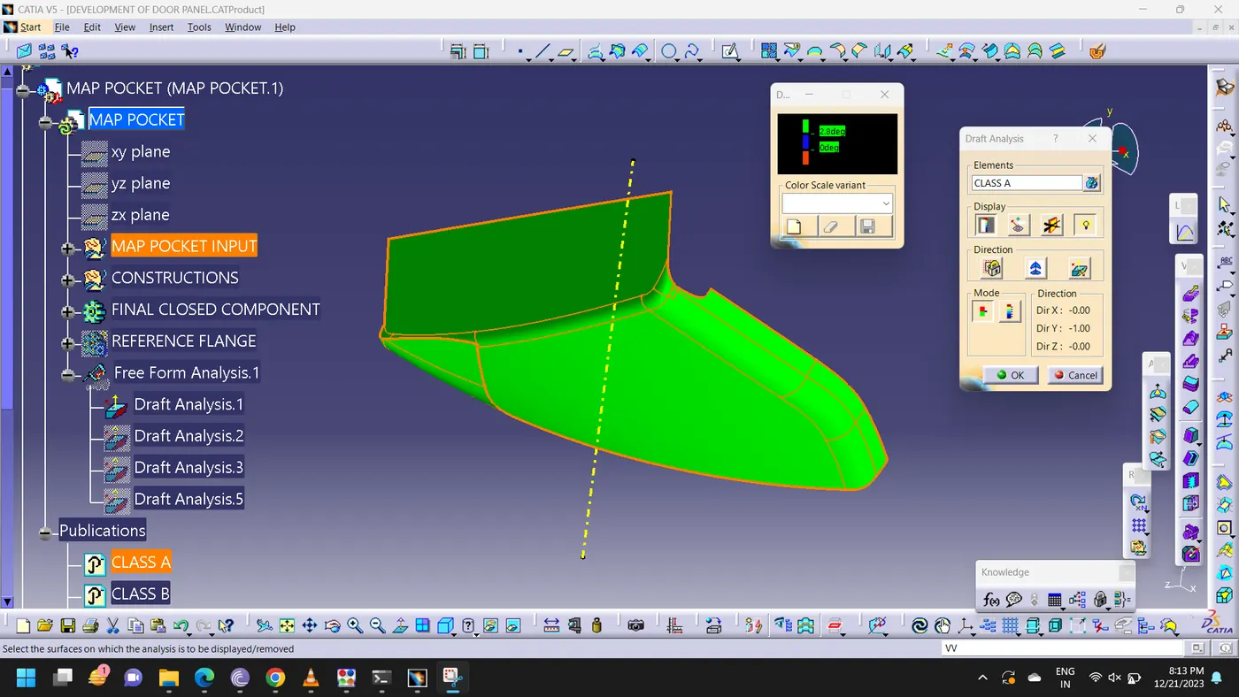
Here, to check the Class-A surface manufacturing feasibiliy as a plastic product Draft analysis was performed on it at 3 degrees.
Draft Analysis: It is performed to check the manufacturing feasibilty of a component or part, in plastic manufacturing process we generally provide 3 degrees draft and 0.5 degree draft in critical conditions. To perform draft analysis first tooling axis was created by taking a point on surface and line was created in the direction in which part will form easily with provided draft.
Map Pocket Class-A surface Draft analysis along Tooling Direction
Map Pocket Class-B Surface Creation
The class B surface is created by extracting and extrapolation of each surfaces of class A
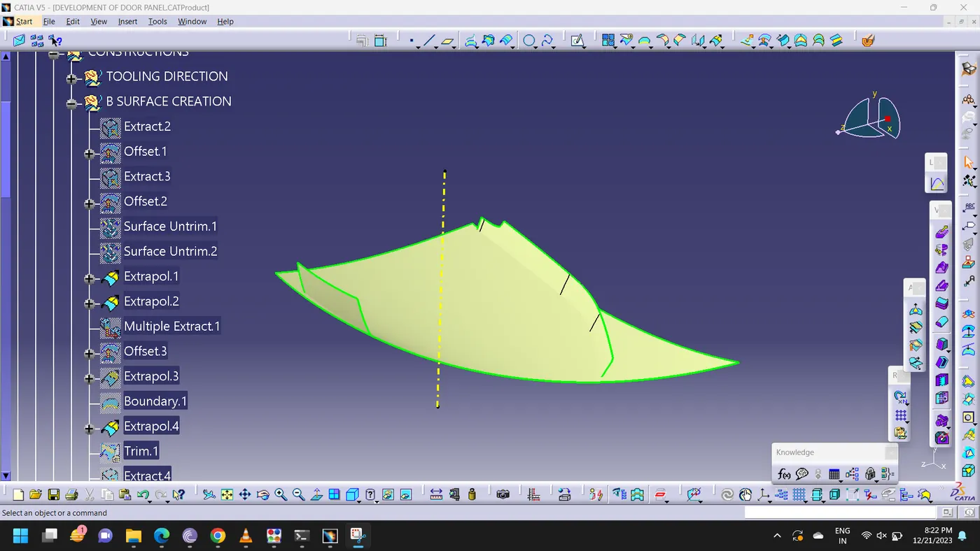
On extrapolating the each surface after offseting to 2.5 mm then all the surfaces will be able to intersect with other so then we can trim them together by using trim tool in a generative surface workbench.
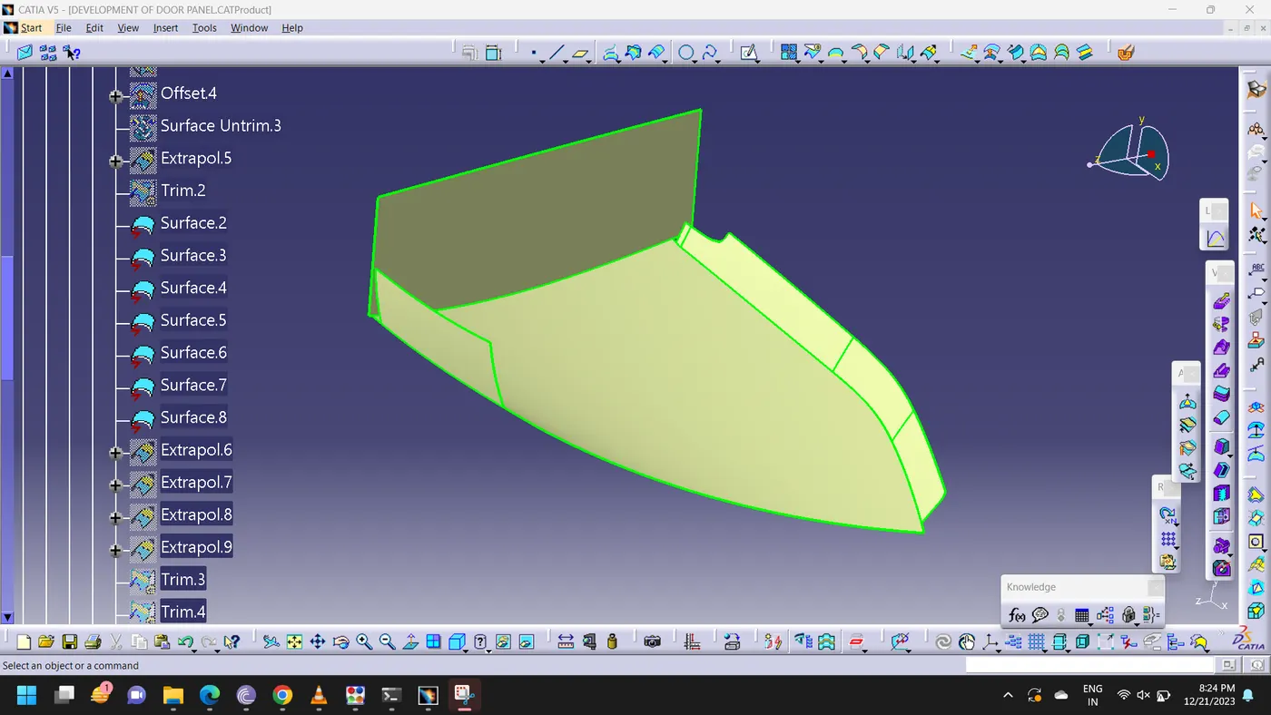
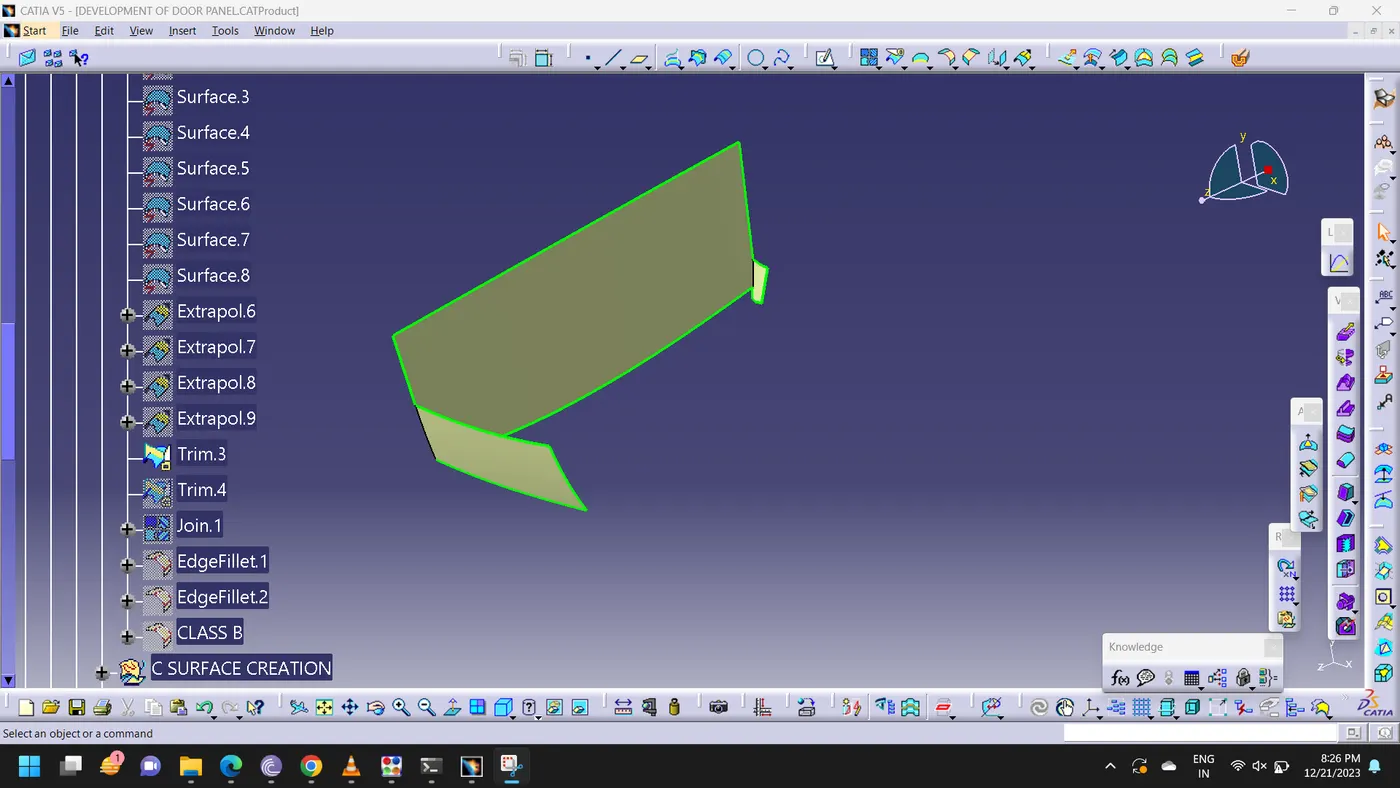
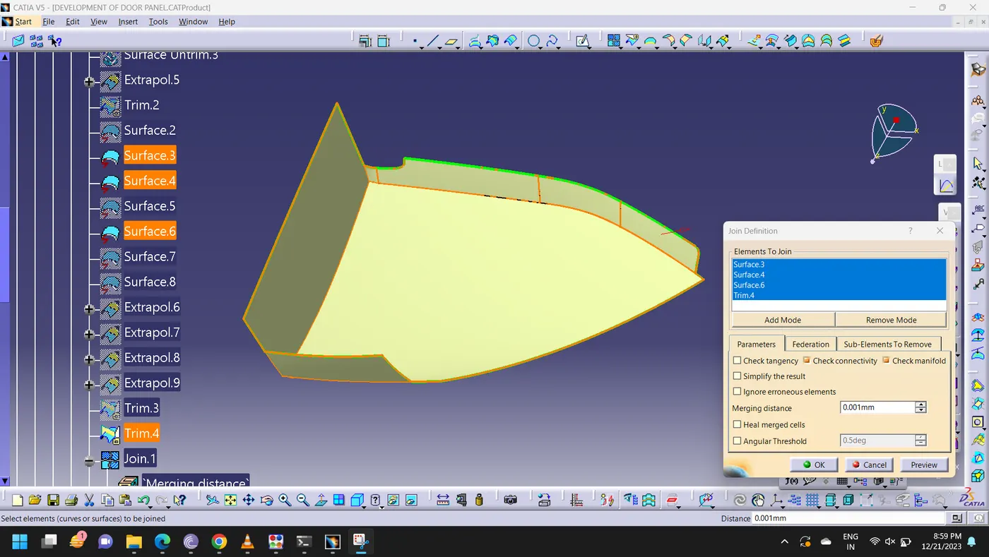
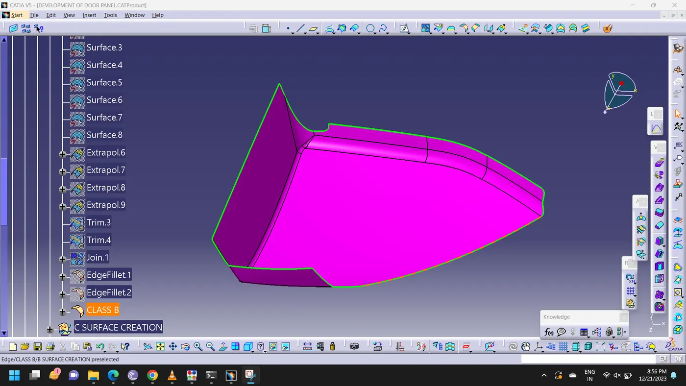
After Trimming all the surfaces we can give edge fillet to the surface as per class A in order to complete the Class B surface
Map Pocket Class-C Surface Creation
Class-C surface was swept from the boundary of the Class-A surface. Class-C surface was swept with 90 degree along Class A Surface.
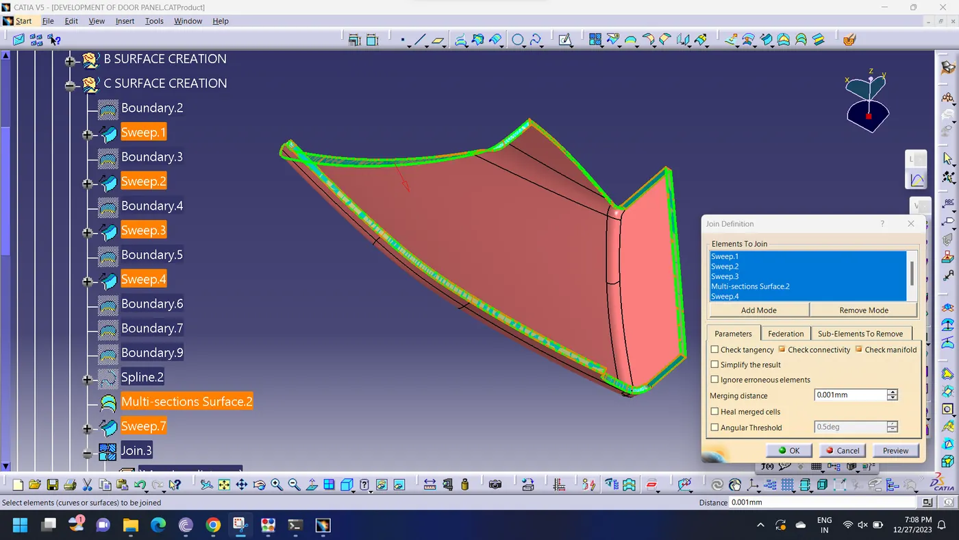
Now after joining all the sweeps together along with multi-section surface we will get a Class C surface.
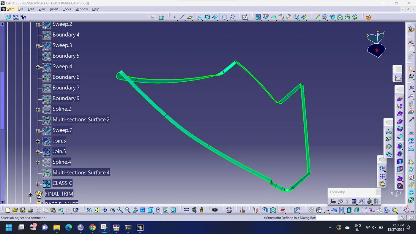
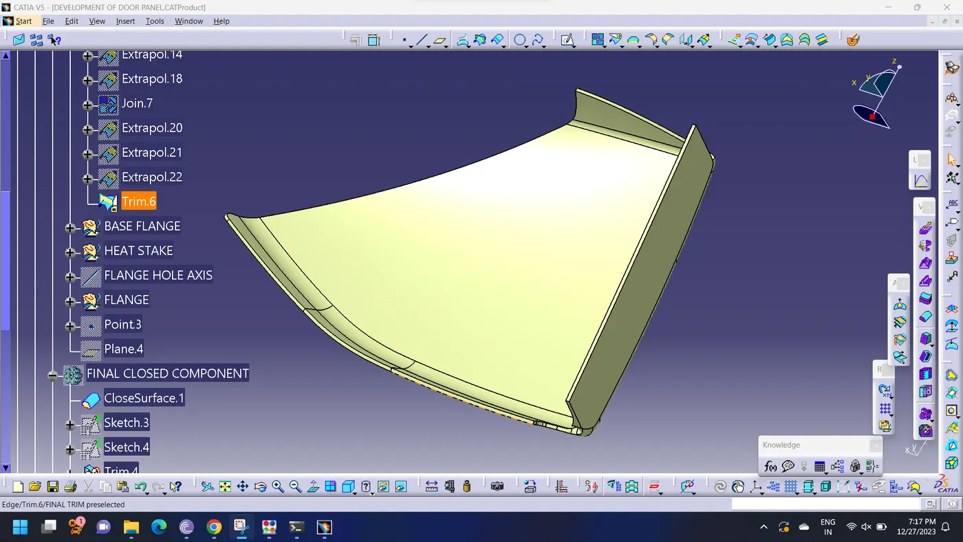
After creating Class-B and Class- C surfaces, both surfaces wer timmed with Class- A surface to form a closed surface of map pocket.
Map Pocket Closed surface
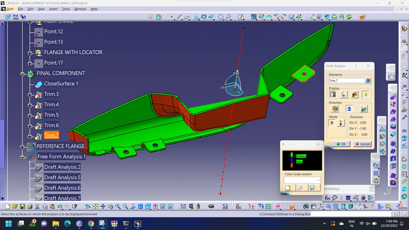
Closed surface draft analysis for analyzing Class-B and Class-C surface
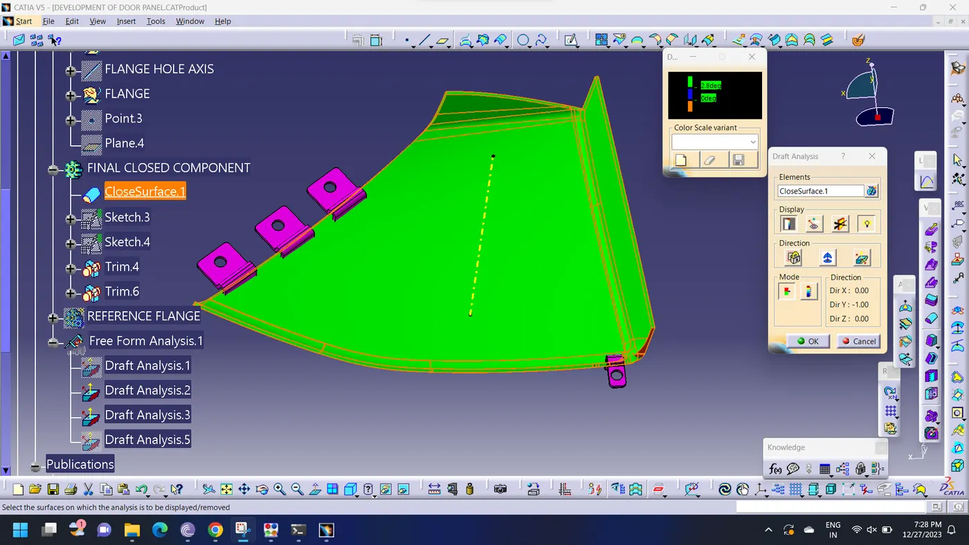
Creation of Flanges as an engineering feature
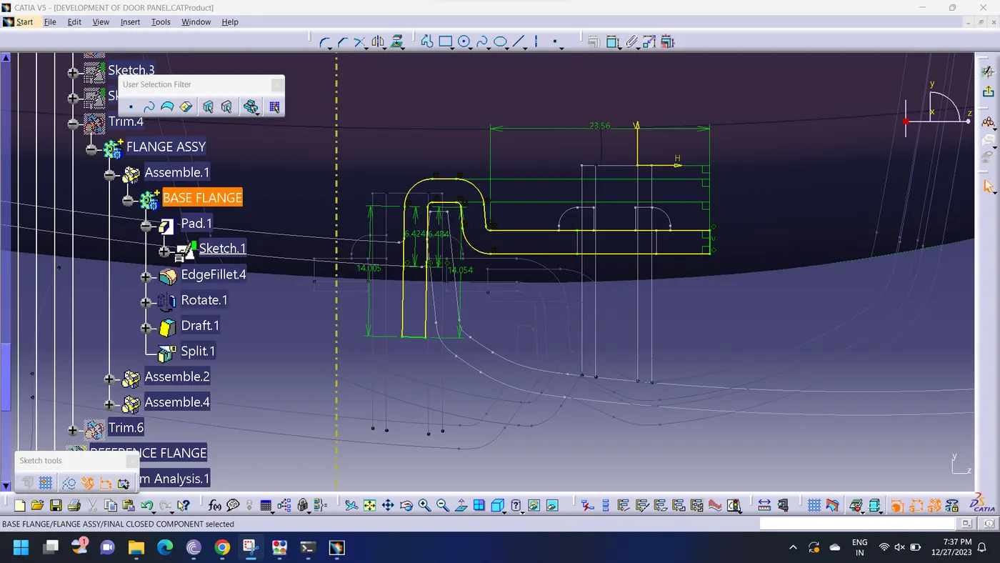
As per given geometry of master section flange sketch is created below
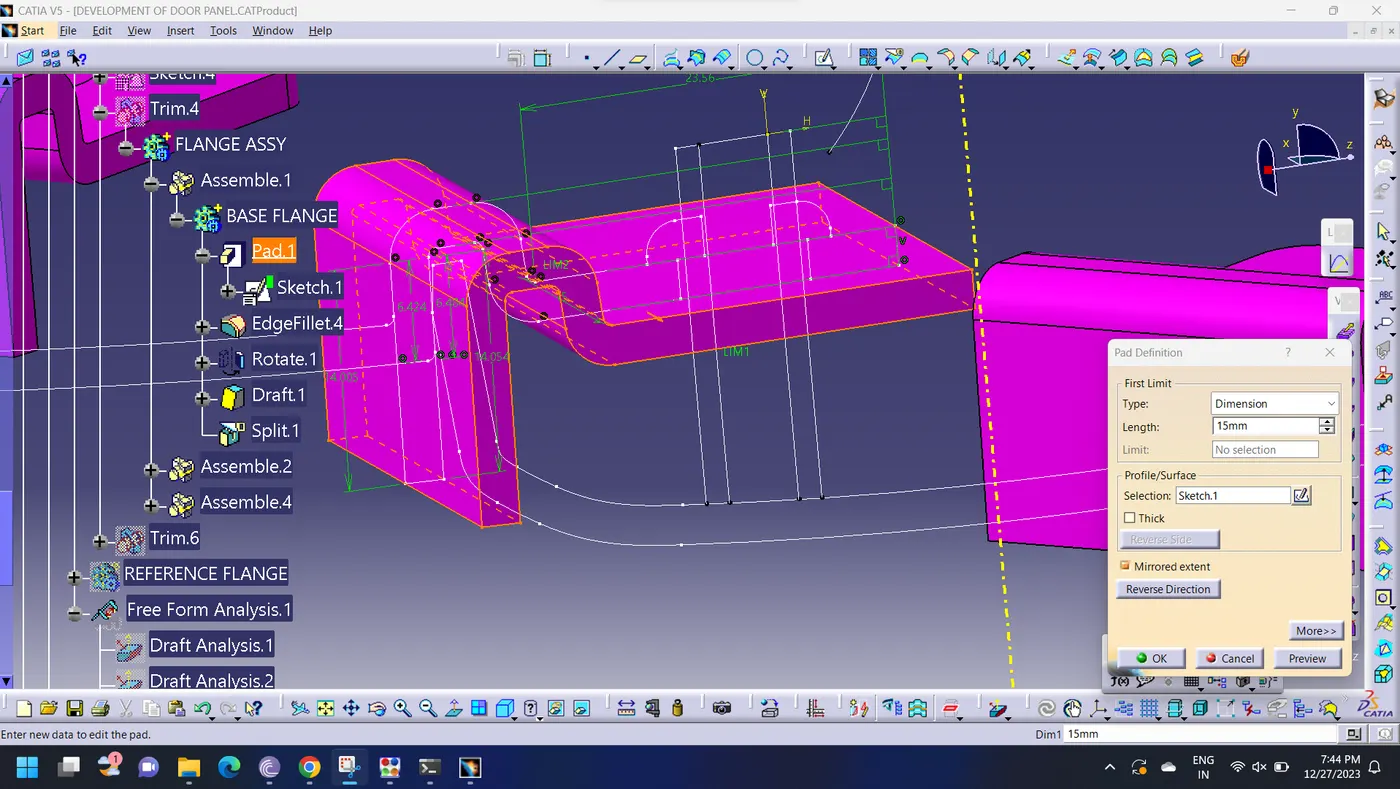
Flange length of the Pad is taken as 30 mm as design standards
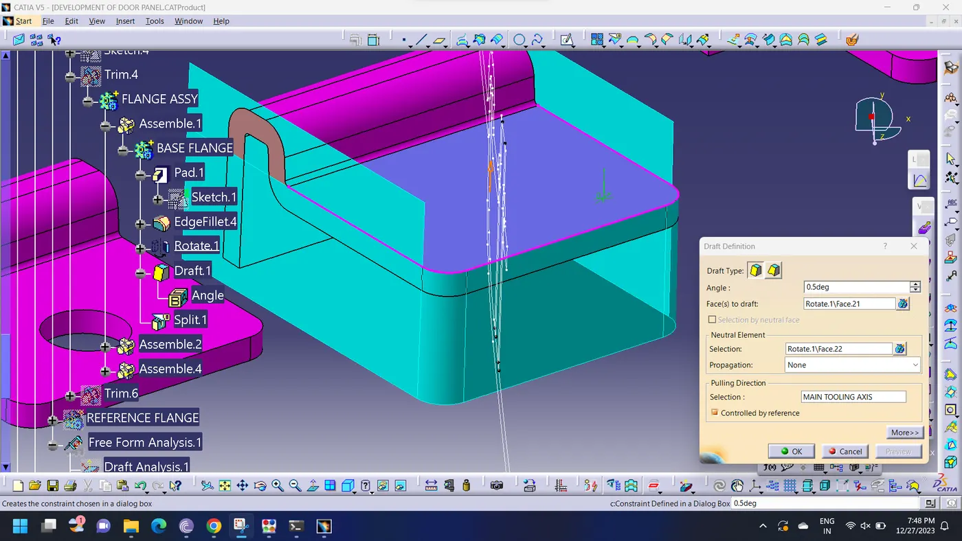
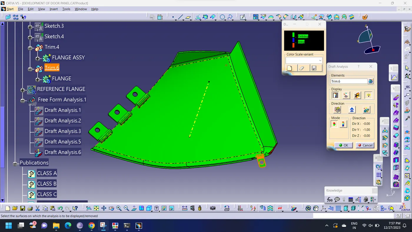
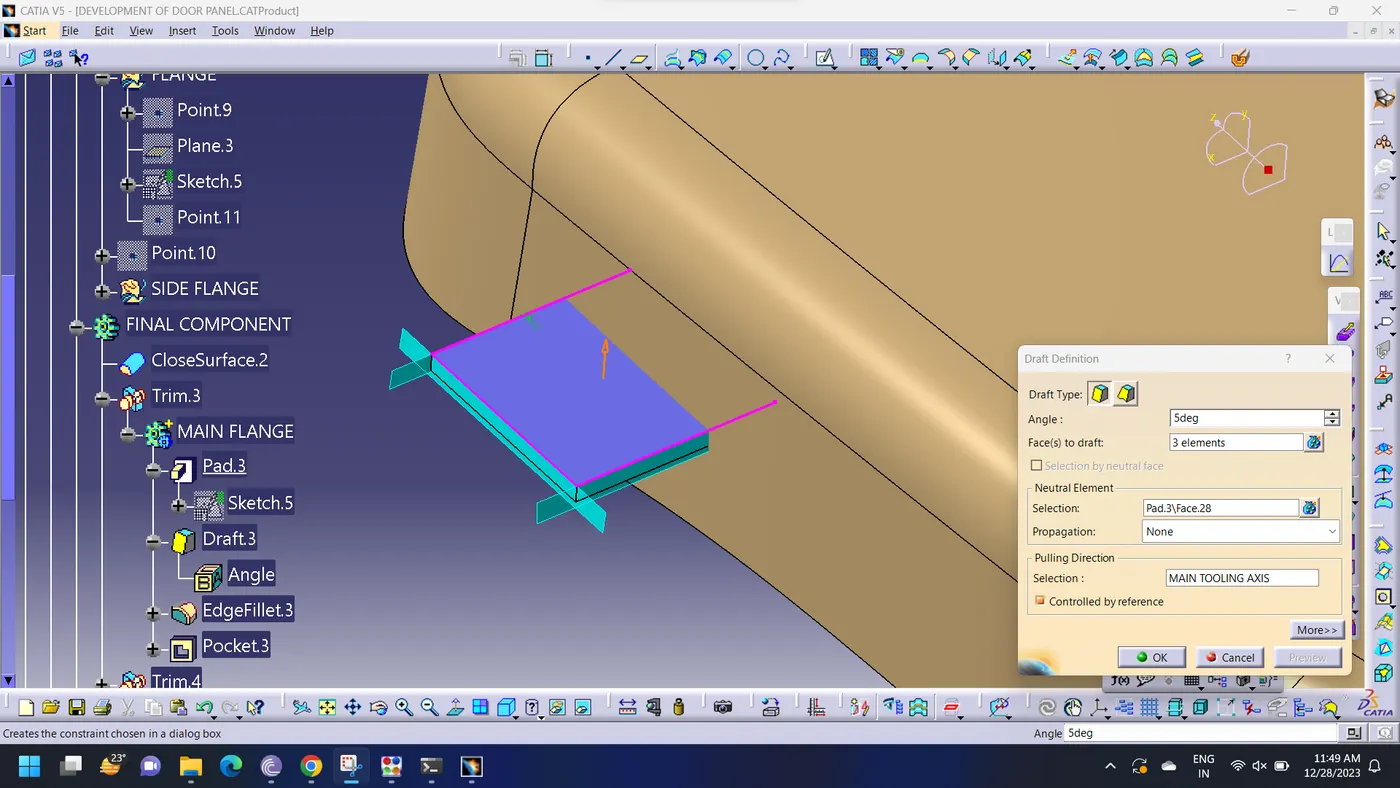
0.5 Degree draft is provided to each flanges as per design standards
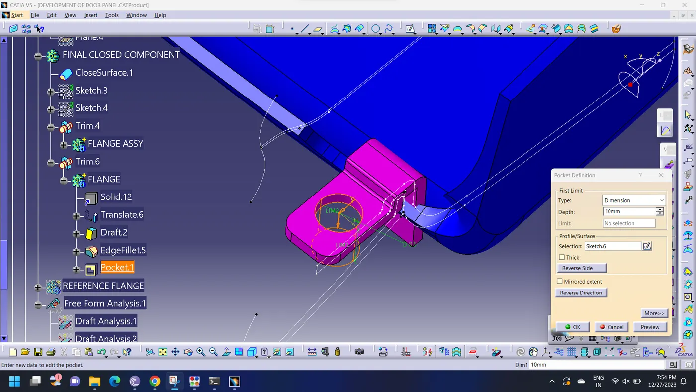
Draft Analysis of attachment features at 0.5 degree.
BOTTLE HOLDER DESIGN
Class-A Surface of bottle holder
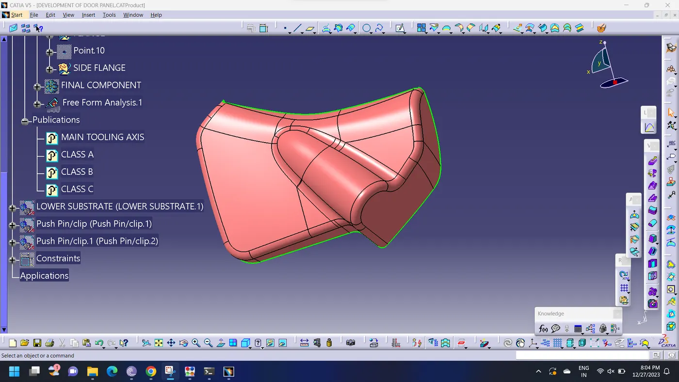
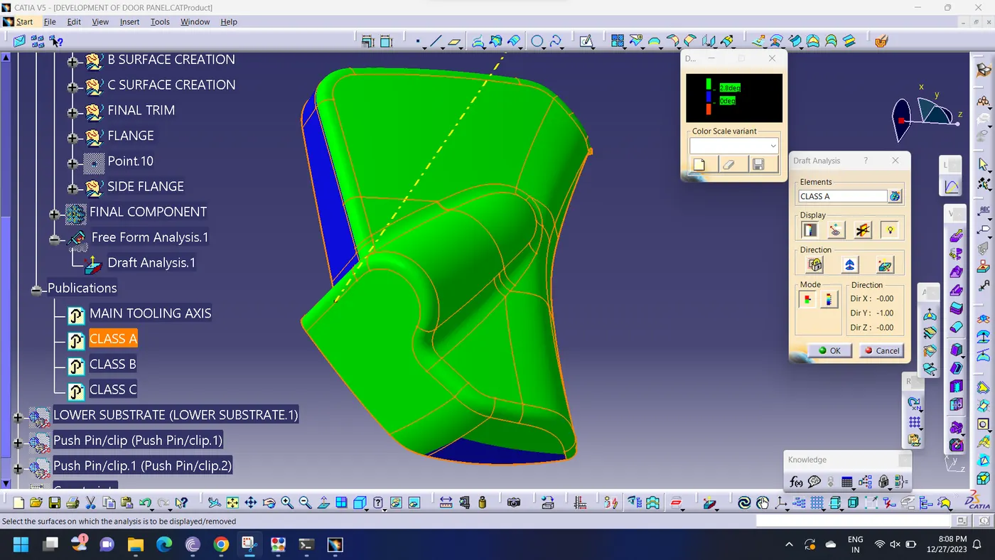
Draft Analysis performed on Class-A surface along Tooling Direction
In this part one tooling axis was not able to clear the draft of the component, so side sore axis was provided to form the component. This issue must be discussed with other designers like NPD CAD team or Class-A modeler because using side core can be expensive way to manufacture a plastic component. So, if it possible to make changes in design, should be done which helps in easy and low cost manufacturing of component.
Main Tooling Axis of Bottle holder
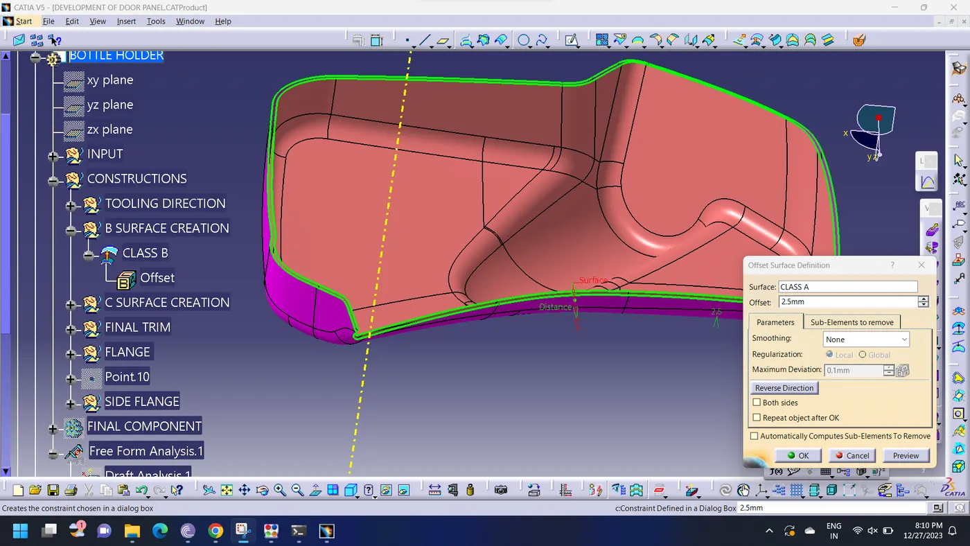
Class-B surface created by offset of 2.5 mm of Class-A
As we can see that the most of the edges of class A surface appearing perpendicular from the tooling direction hence here we use 90 degree with reference surface method to create sweep
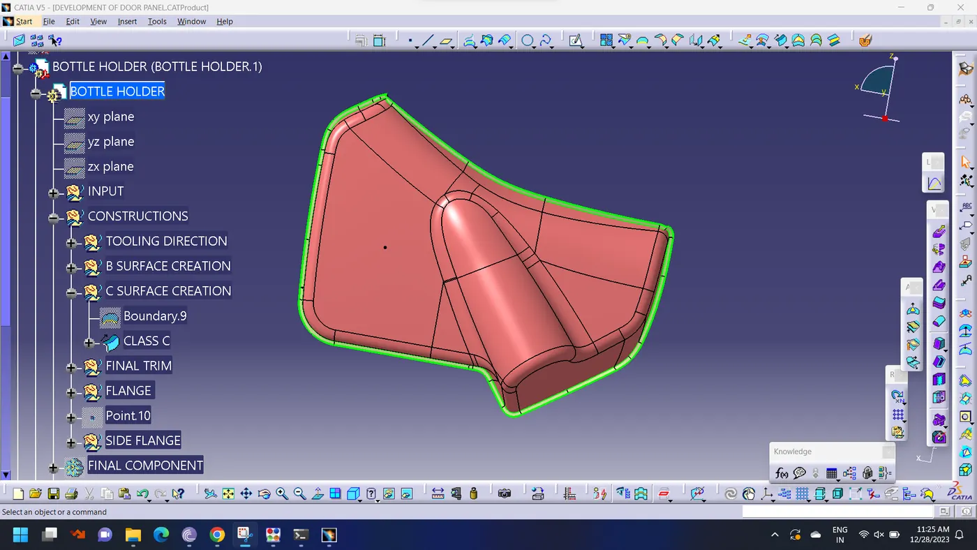
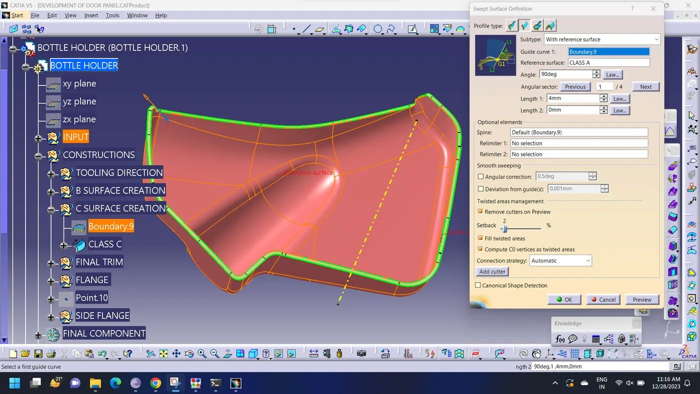
Here we got Final C Surface
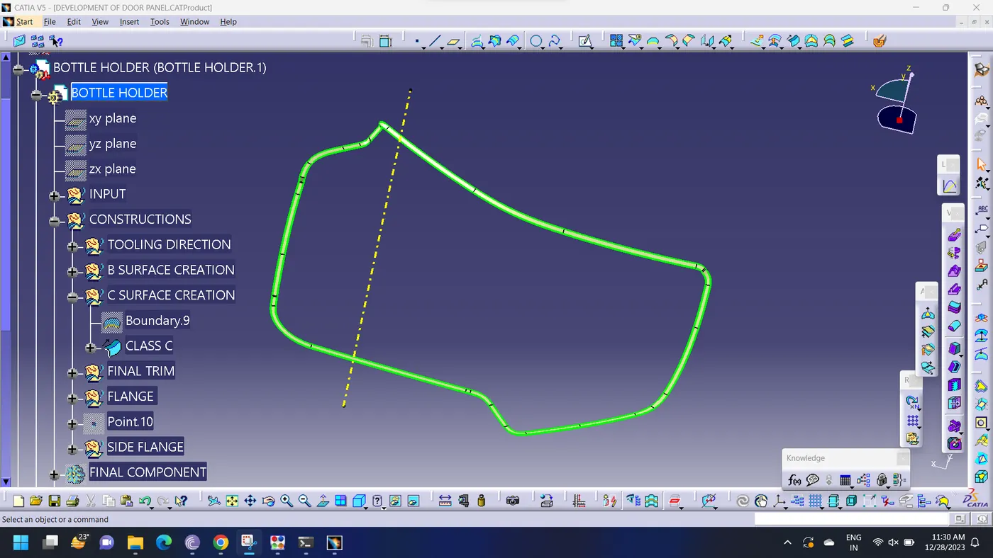
Final Trim surface
On trimming of Class A, B and C surface together we will get the closed surface
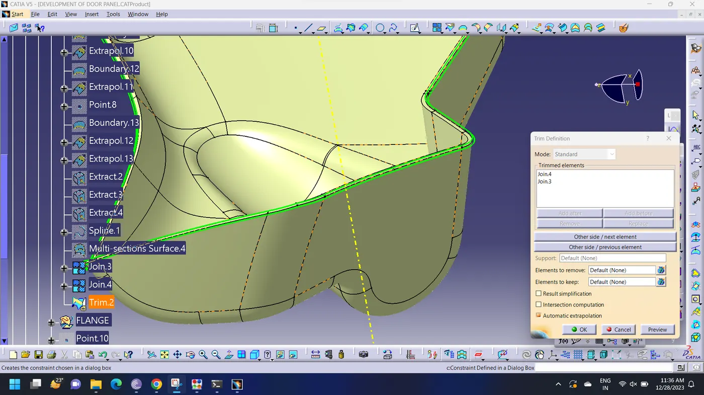
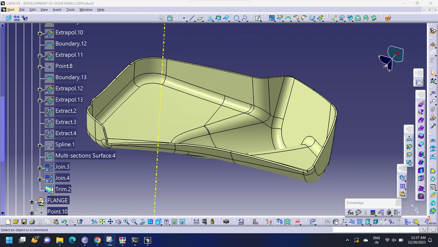
After Creating Closed Surface of bottle holder, It was converted into solid body and attachments features were created with 0.5 degree draft for easy manufacturing process.
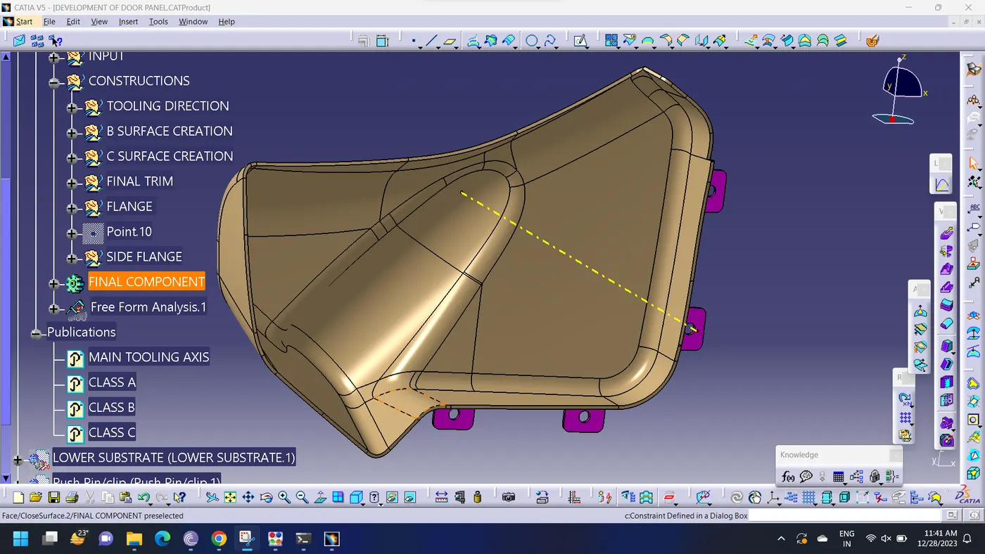
Flange Creation on BOTTLE HOLDER
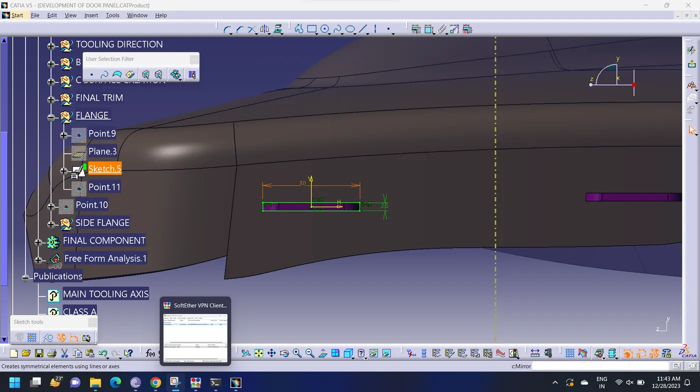
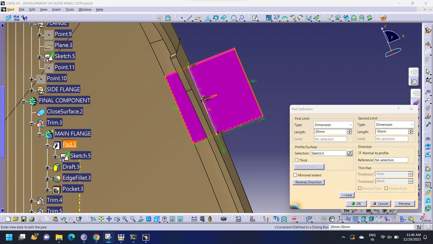
0.5 degree draft is provided to the each Flange as per design consideration and standard rules.
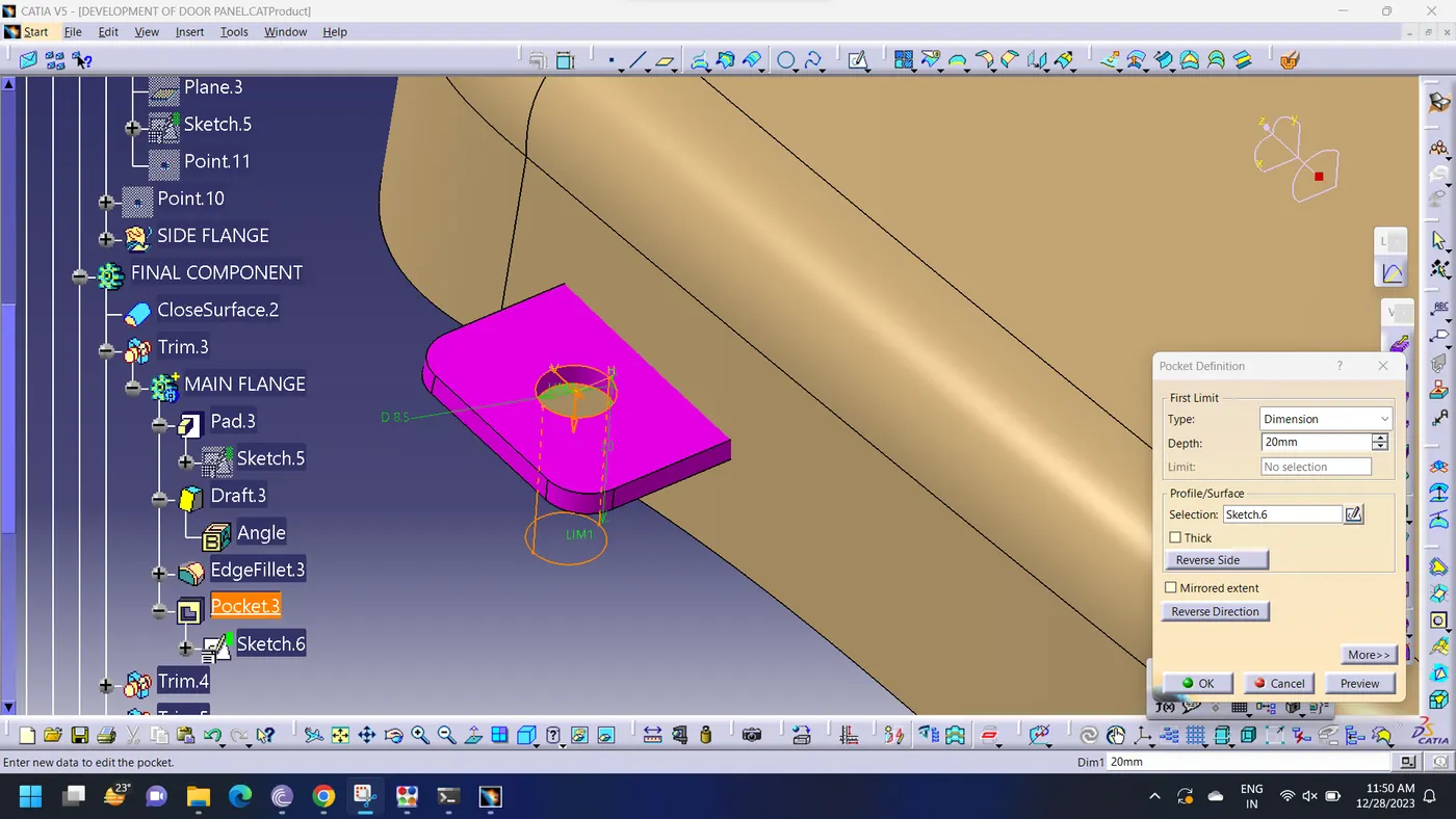
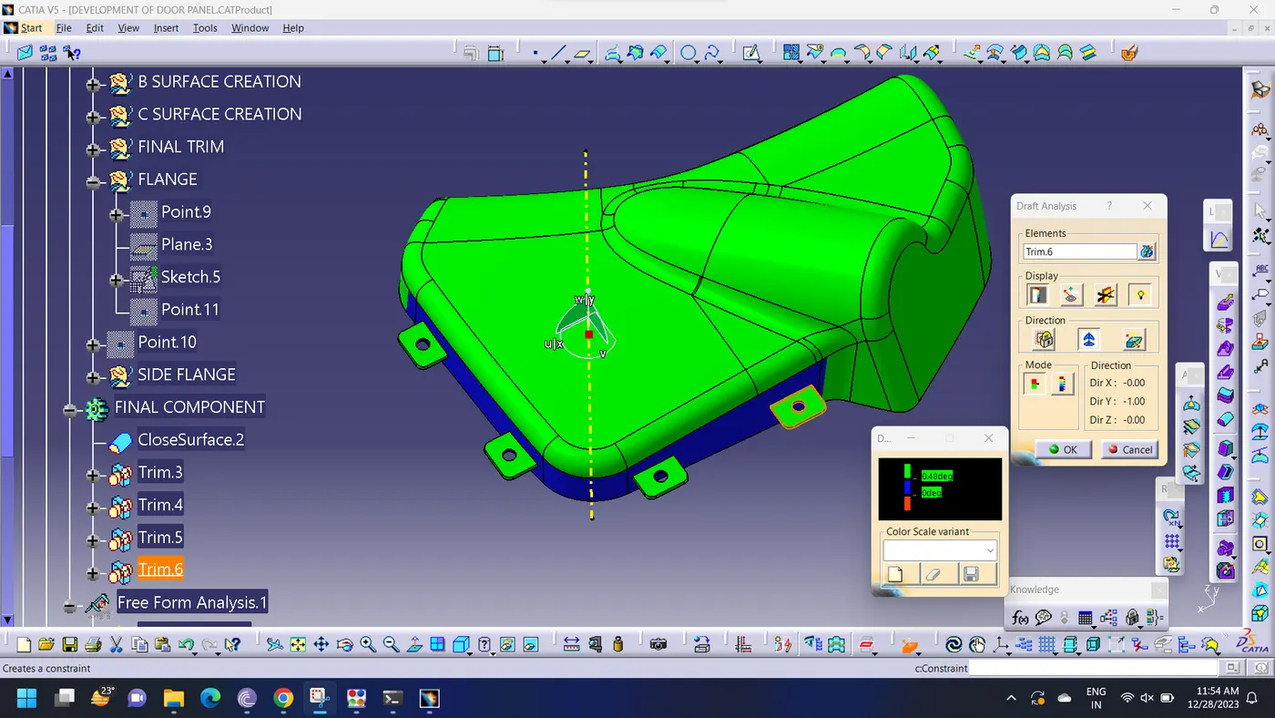
Draft Analysis of attachments features with 0.5 degree draft
LOWER SUBSTRATE DESIGN
Class-A surface of Lower substrate
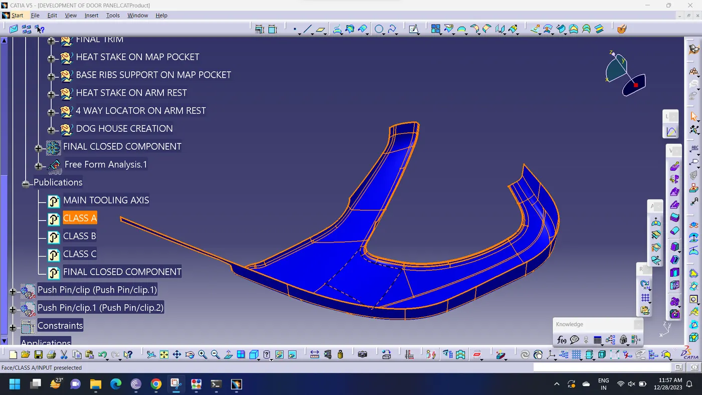
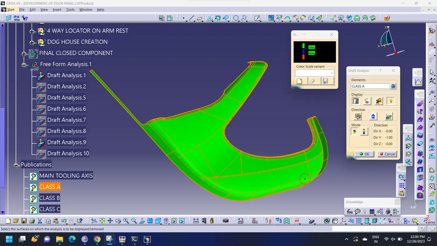
Draft Analysis on Class-A surface with 3 degree draft along Tooling Direction
Creation of Class B surface
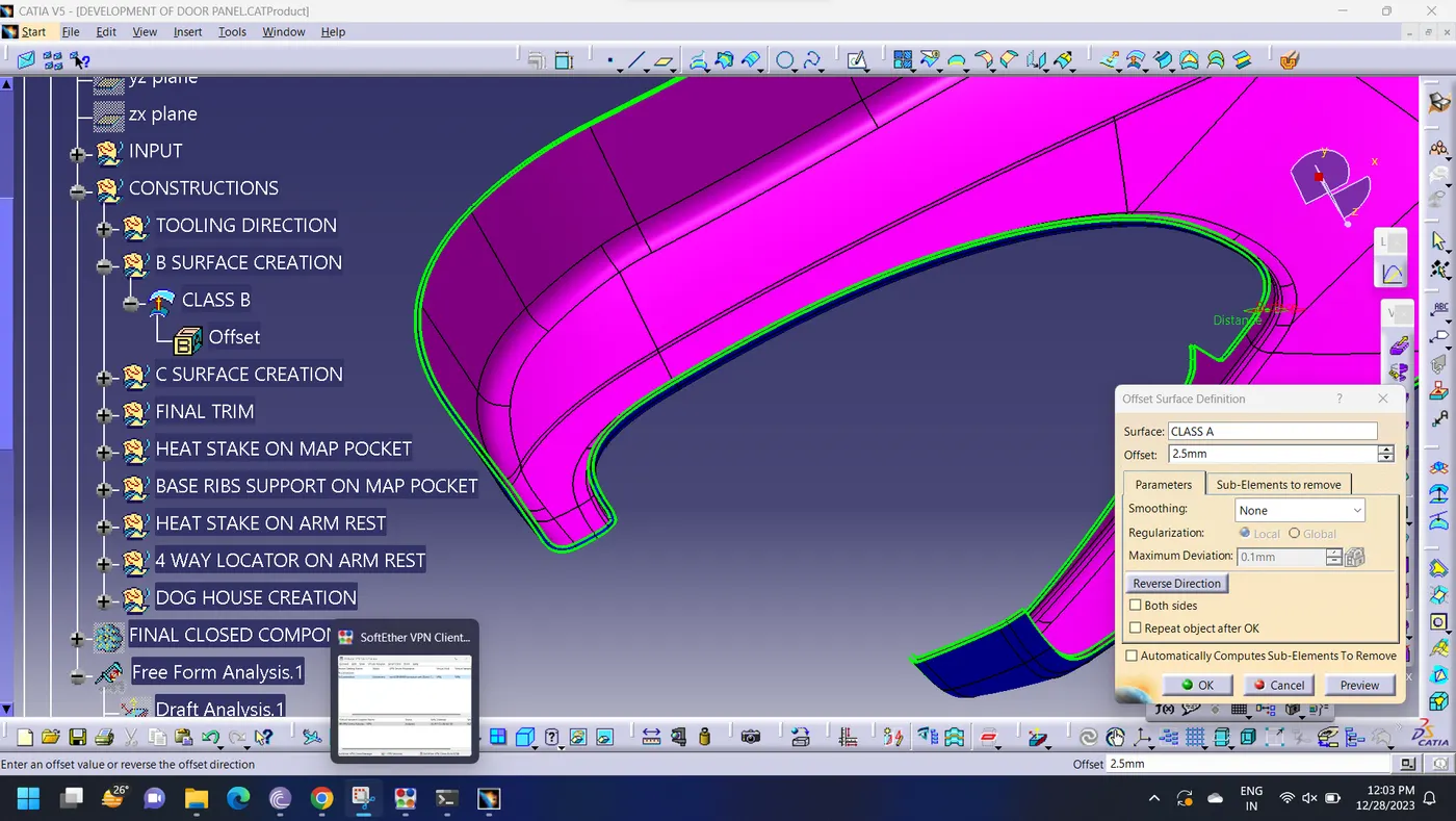
Class-B surface offset at 2.5 mm from class-A as per thickness given in the master section
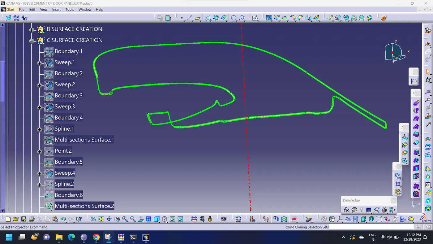
Creation of Class C Surface
As we can see that the most of the edges of class A surface appearing perpendicular from the tooling direction hence here we use 90 degree with reference surface method to create sweep
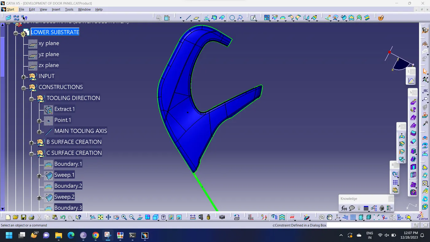
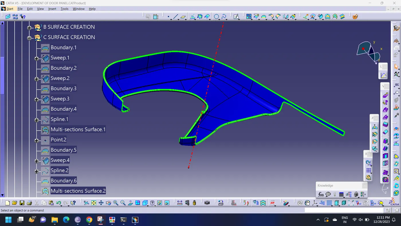
Trimmed Class-C surface
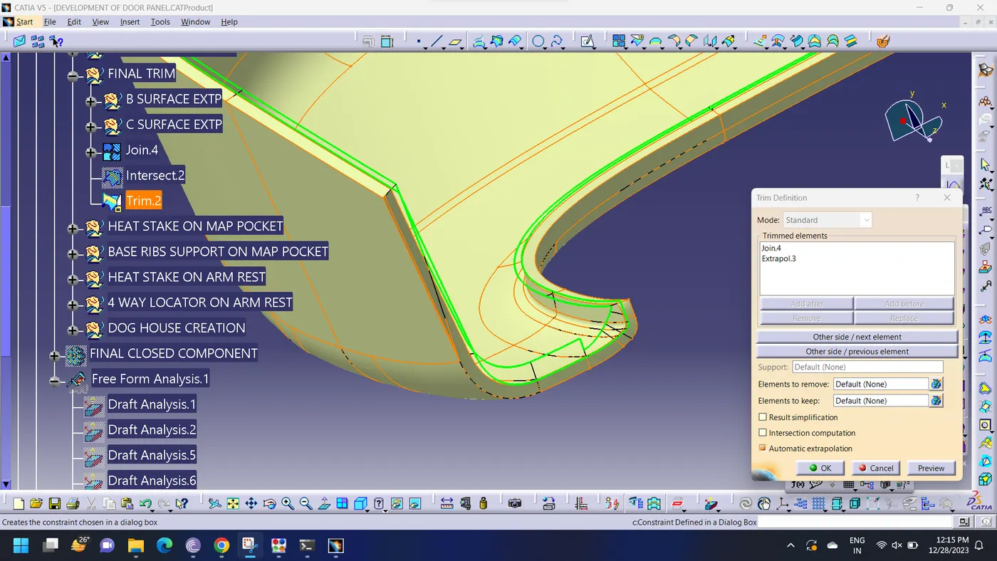
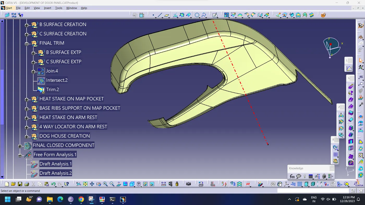
Final trim surface
Attachment feature creation on Lower Substrate
1. HEAT STAKE
- Thermal heat staking is an assembly method that uses the controlled melting and reforming of a plastic and stud or boss to capture or lock another plastic or metal component of an assembly in place. The plastic stud provides through a hole in the component to be locked in place. The heated thermal tip contacts the top of the stud, which melts and fills the volume of the tip cavity to produce a head, locking the component in place.
- Below image shown the process of heat staking.
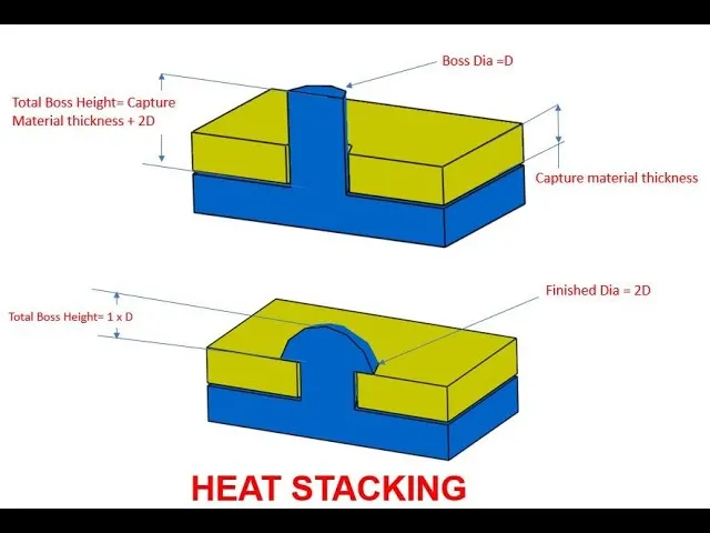
- The Progressive melting of plastic under continues pressure forms the head. when staking, the right combination of heat and pressure for the application is critical.
Advantages of using heat stake in automotive industry:
- Simplification of machinery
- Reduced cost of machinery
- Multiple fastening points
- Allows higher density of welds compared to hot air cold form or ultrasonic welding.
Creation of heat stakes
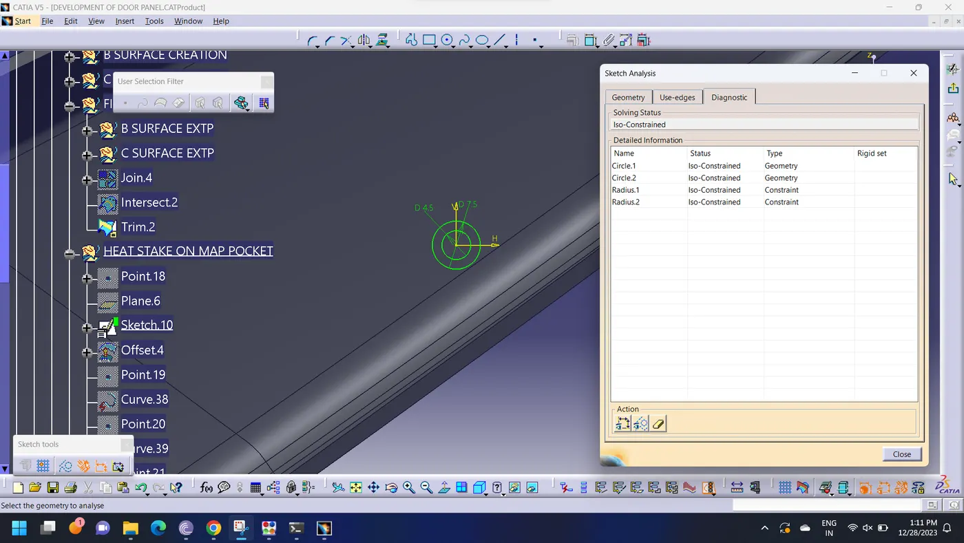
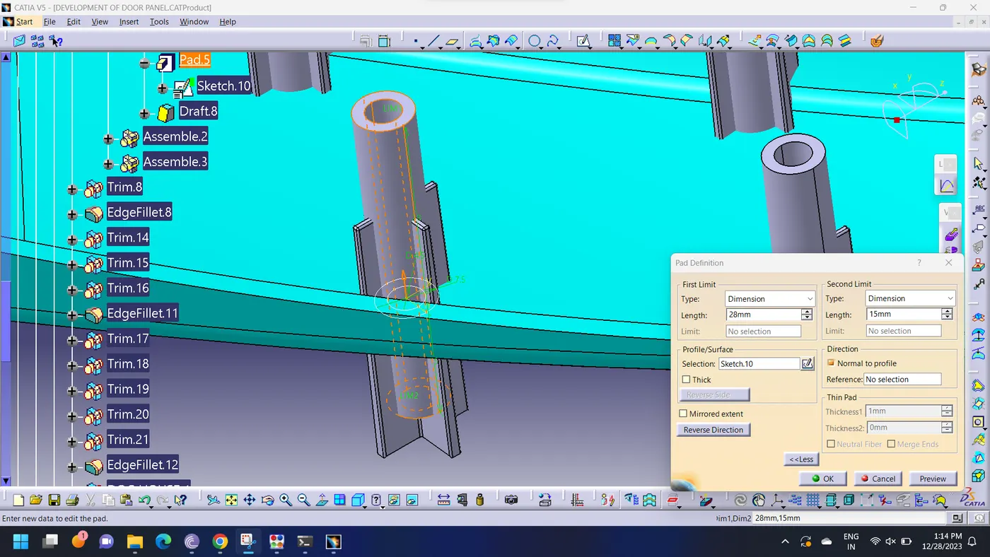
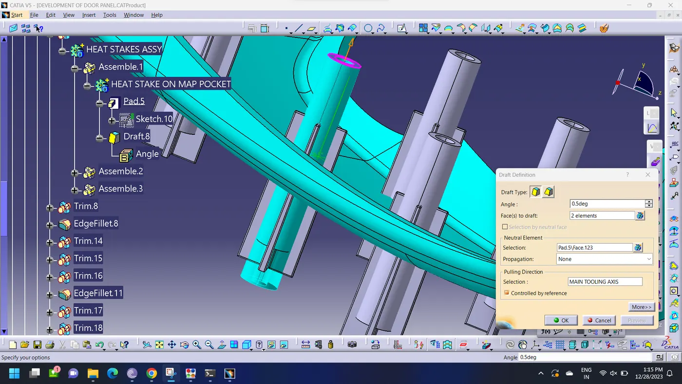
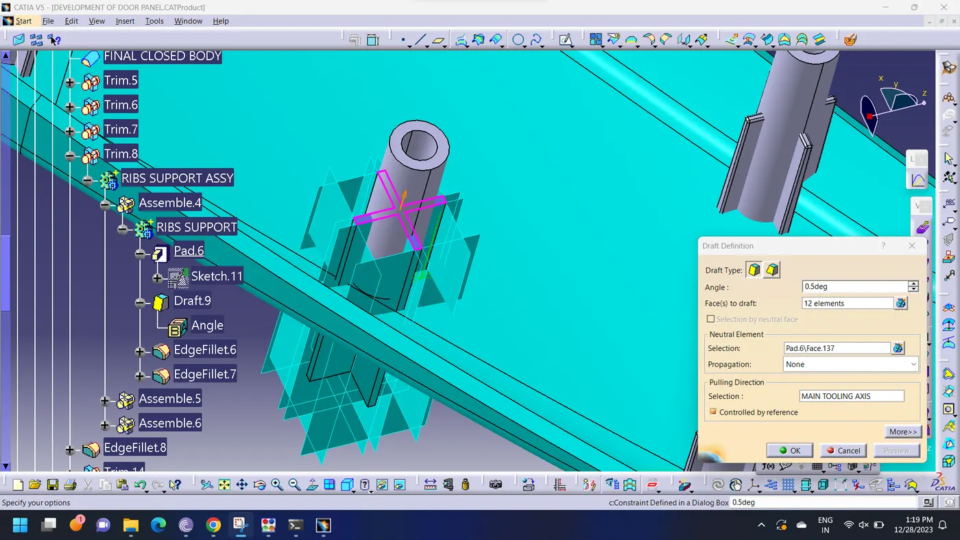
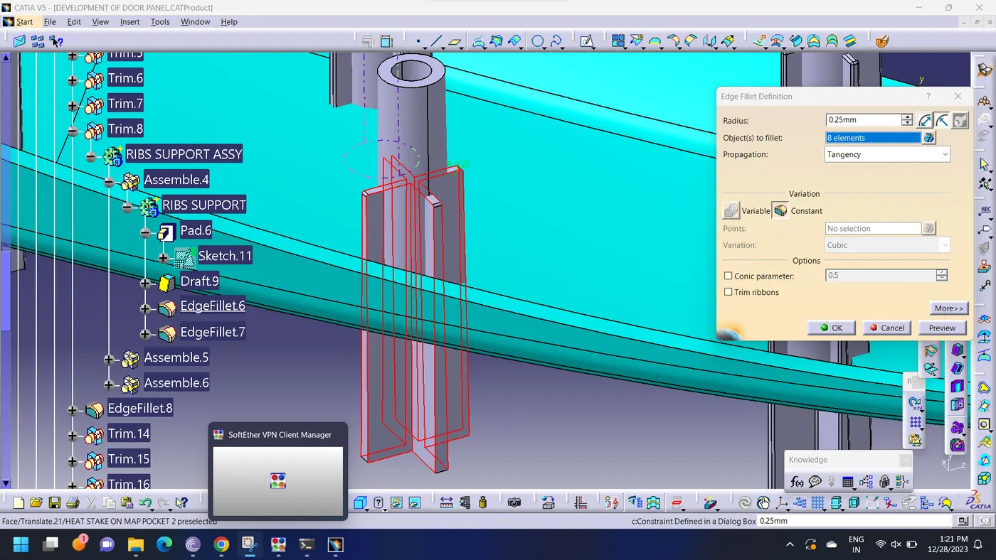
Ribs support on heat stakes
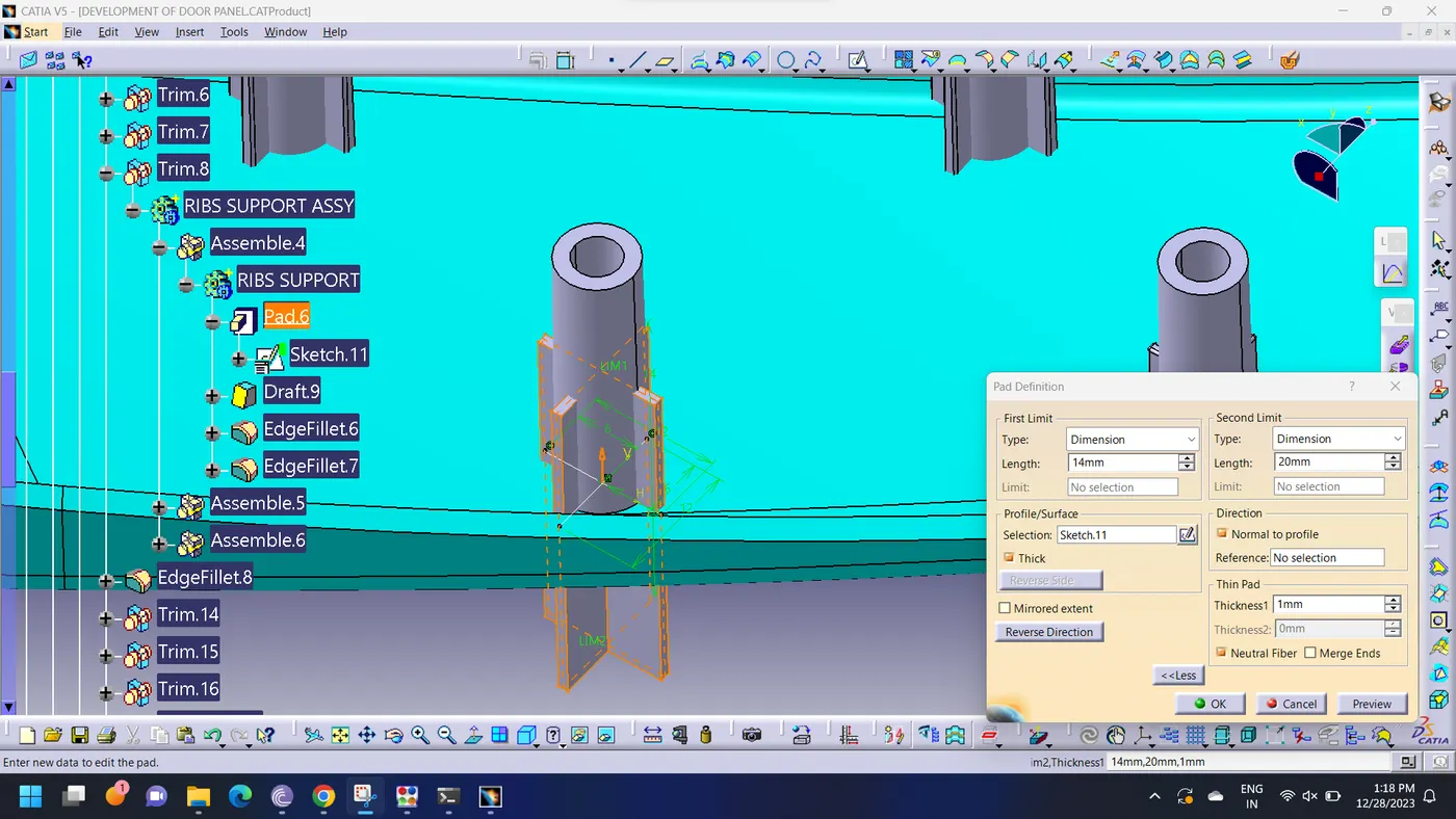
Providing 0.5 degree draft on each surface of ribs and also 0.25mm egde fillets is provided at all the sharp corners.
2. RIBS DESIGN
- Ribs are used to improve the stiffness and strenght of the molding parts without increasing the overall wall thickness
- Ribs acts as a support member for assembly like fixture to locate correctly for mating part and also arresting the components at various conditions
- Ribs acts as a stopper and provides the guiding mechanism for the adjecent parts.
3. DOG HOUSE DESIGN
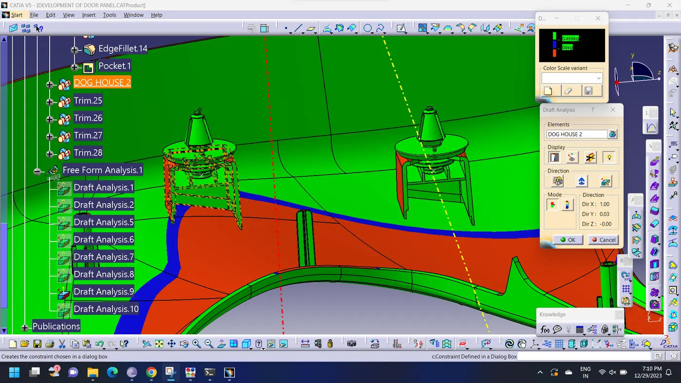
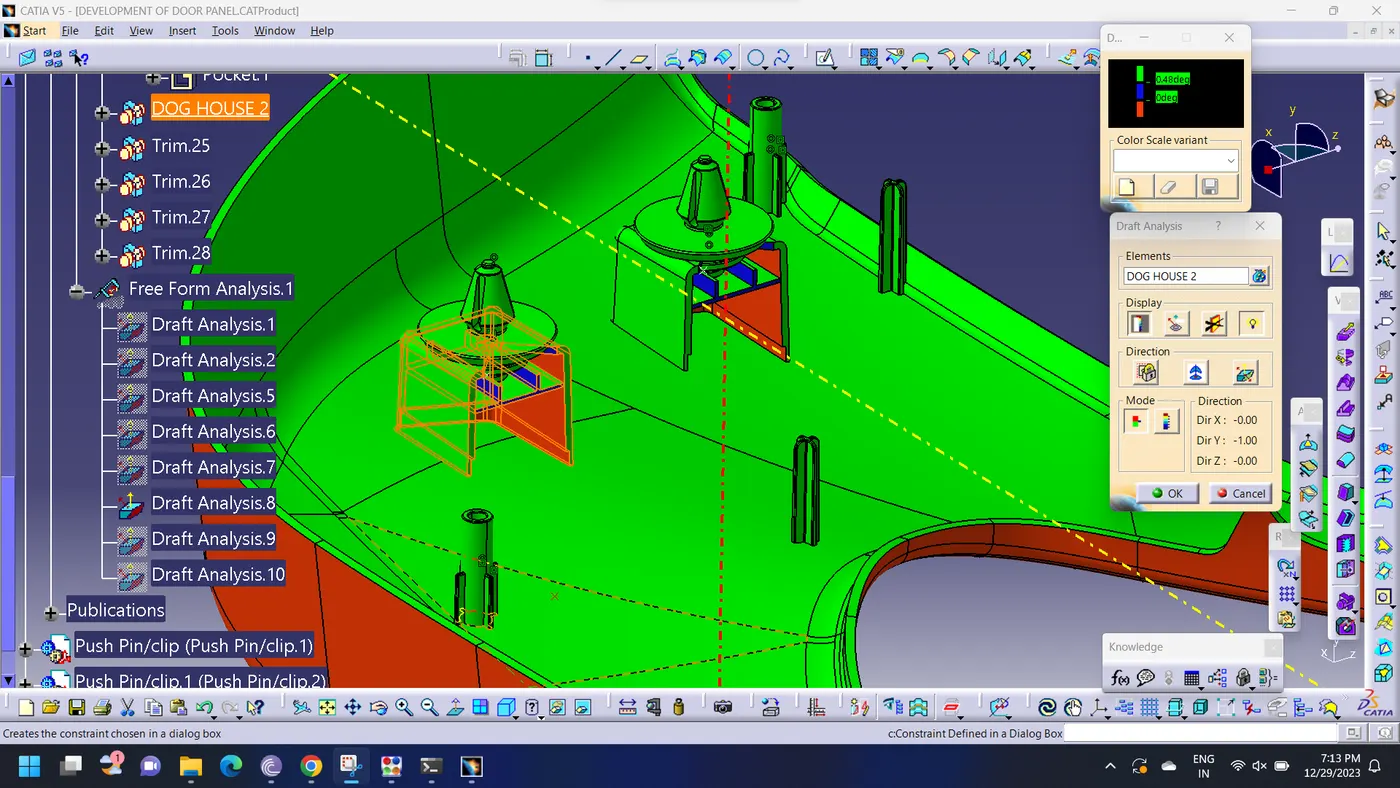
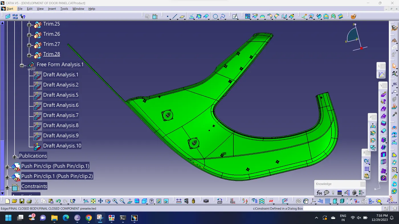
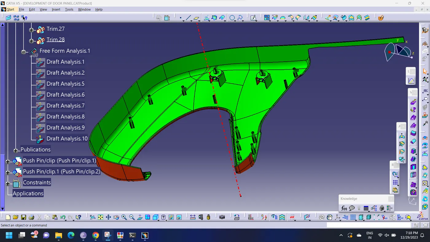
It is a additional feature helps to reduce the sink marks while fixing the bosses on class A. Bosses attachment area were more thicker, because of the boss wall thickness, it leads to sink mark on class A. In order to avoid that sink marks Dog houses plays the major role. The contact area at the very being of dog house wall from the class A has thinner cross section which helps to reduce the sink mark.
4. SCREW BOSS
ARM REST DESIGN
Given class A surface is shown below:
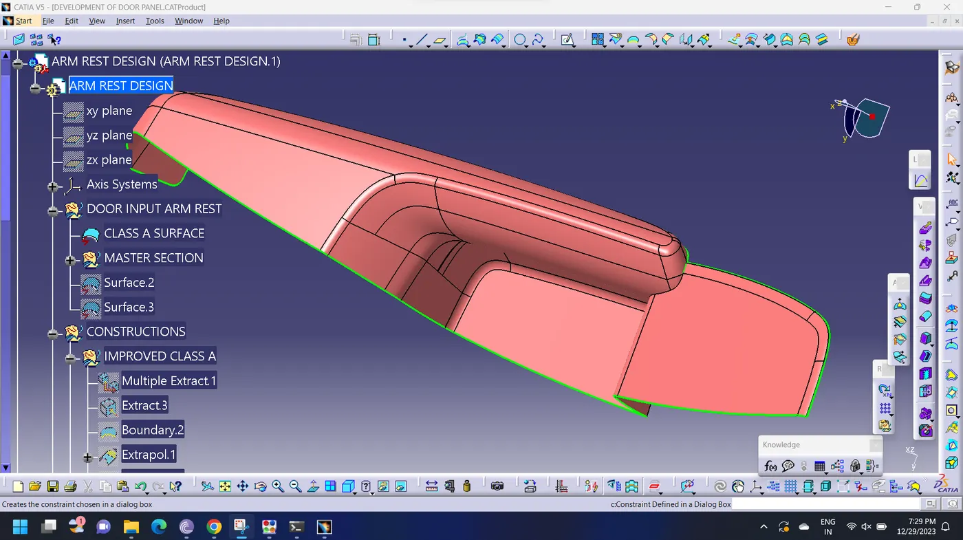
As we see that above given class A surface has some open boundries so we need to rectify that gap between the surface
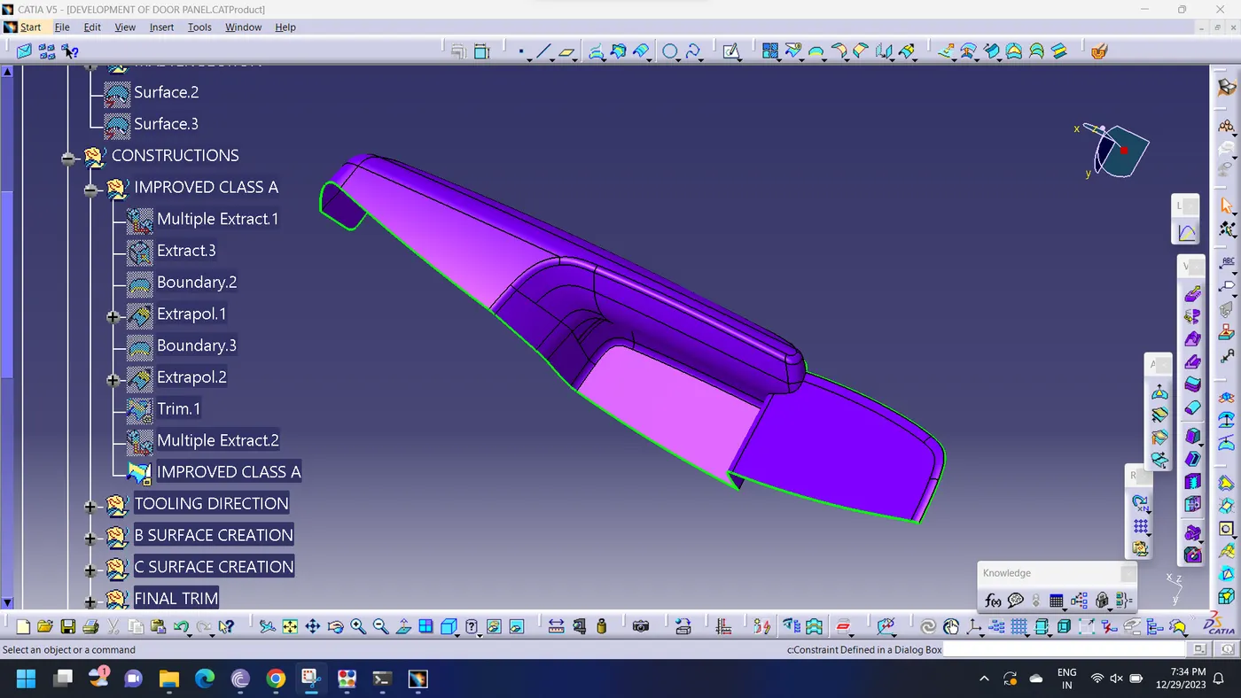
The Improved Class A surface is as shown above.
Draft analysis of class A surface
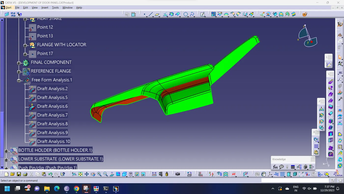
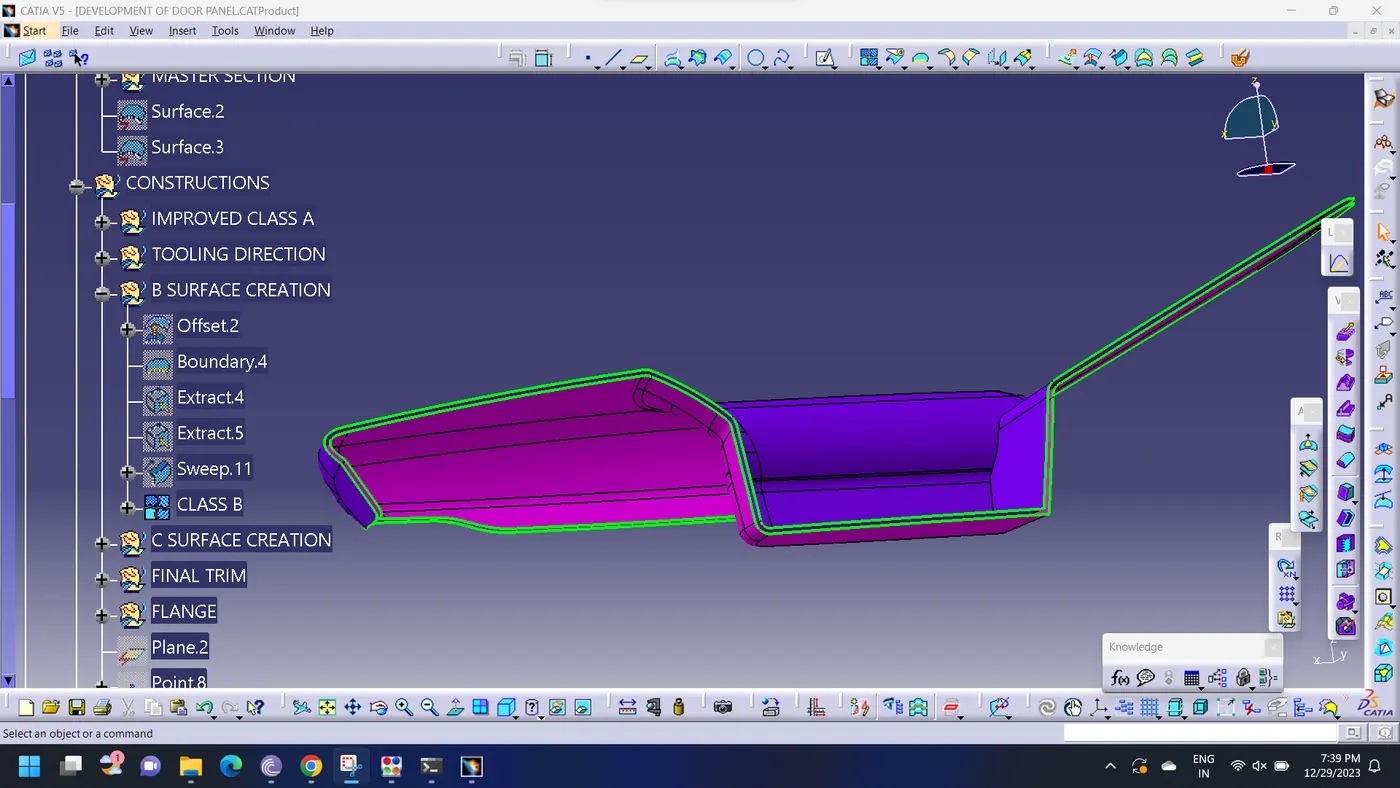
Class-B surface offset at 2.5 mm from Class-A
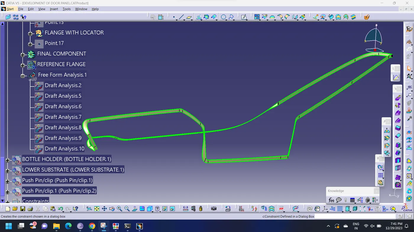
Trimmed Class C surface
Final Trimed surface
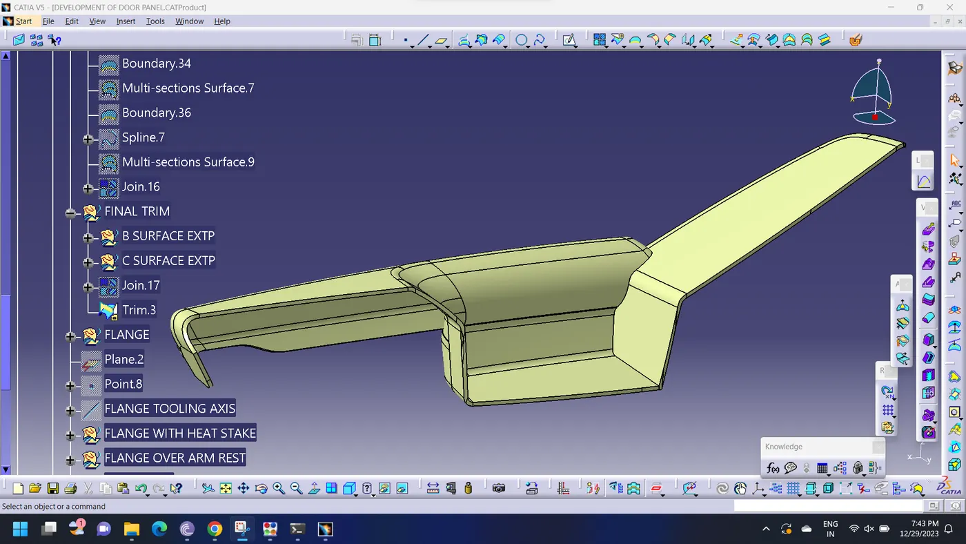
Closed volume ARM REST
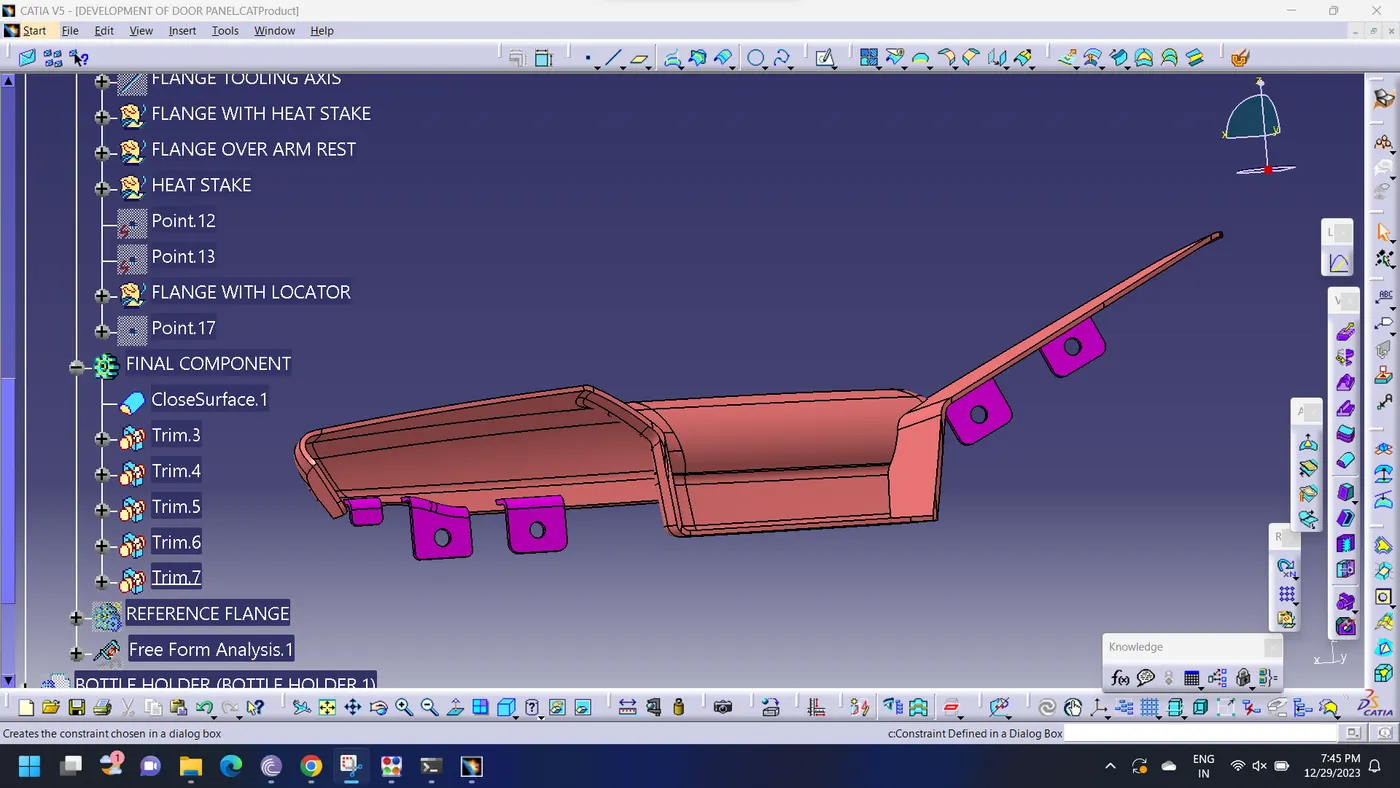
Draft analysis on final closed body
FiNAL DOOR ASSEMBLY
CONCLUSION
Thus the door panel is design and assembled as per design consideration and standards of Tier 1 and OEM Companies.