Week 12- Final project
DEVELOPMENT OF DOOR TRIM PANEL
AIM:
To create a CAD model for door trim panels parts by considering the given inputs of class-A surface along with master section by following design rules followed in OEM and tier 1 company.
OBJECTIVES:
- To create individual tooling axis for the parts and perform draft analysis on the class-A surface.
- To create the class-B and class-C surfaces from the given class-A surface.
- To perform a solid geometry by combining all the surfaces.
- To decide an attachment strategy for the part and create engineering features in reference form the master section provided.
- To perform draft analysis on the solid part model with all engineering features.
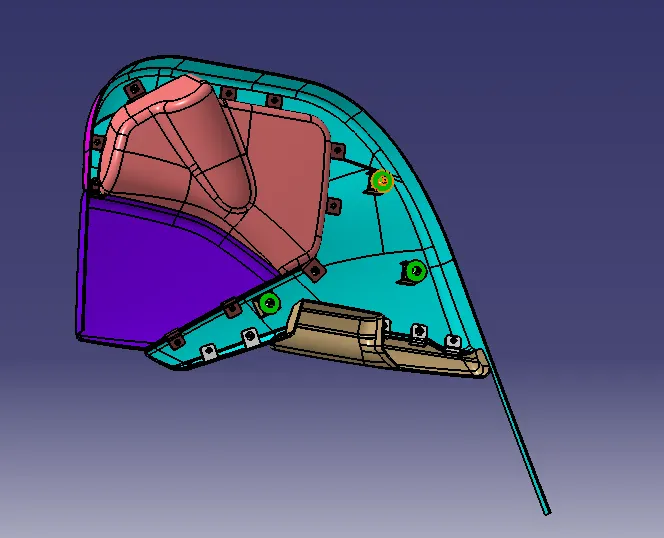
- To assemble all the components together to obtain the final trim.
GIVEN DATA;
Class-A surface for door trim panel:
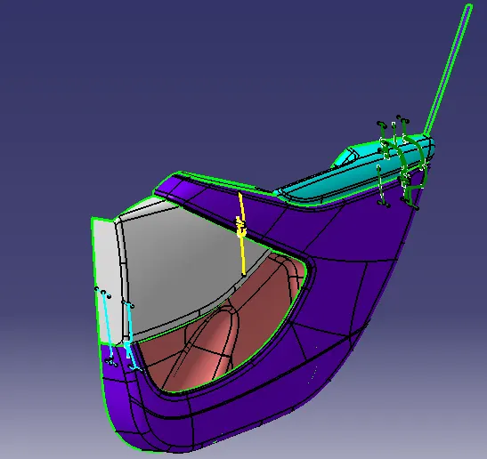
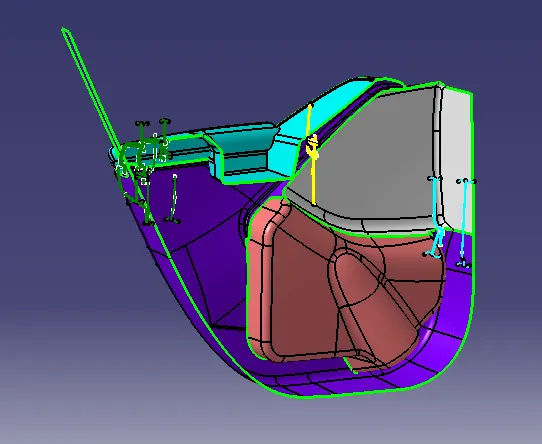
As we know in automotive industry there are complex products that we have to design but this is not possible with simple sketches for that we need Class A Surface.T
The A-surface or the styling surface is first checked for any gaps and other issues in its surfaces. This Surface acts as the input surface so any correction to be done should be with approval from the styling team or done by them. A- perfect surface is the one when a boundary is created, the lines are only on the edges of a component and its holes or cutouts as shown below.
Steps followed for completion of project:
The door trim panel is created by follwing steps -
- To check given Class A surafces for any modification.
- To segregate given surafces into separate part body namely Lower Substrate , Arm Rest , Map Pocket , Bottle Holder.
- To work individually on each part.
- To create tooling axis for part.
- Draft analysis on class A surafce.
- Creation of class B and Class C surafce.
- Craete closed body from Class A , B and Class C surface.
- Follwed same procedure to craete all parts .
- Then create attachement features for all parts.
- Then do Draft analysis on final parts and then constrain them for assembly.
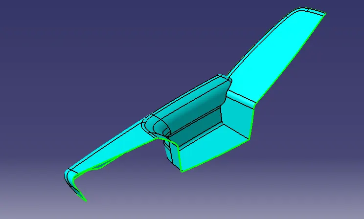
ARM REST
Class-A surface;
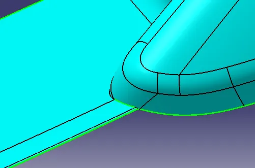
CLASS-A IMPROVEMENT;
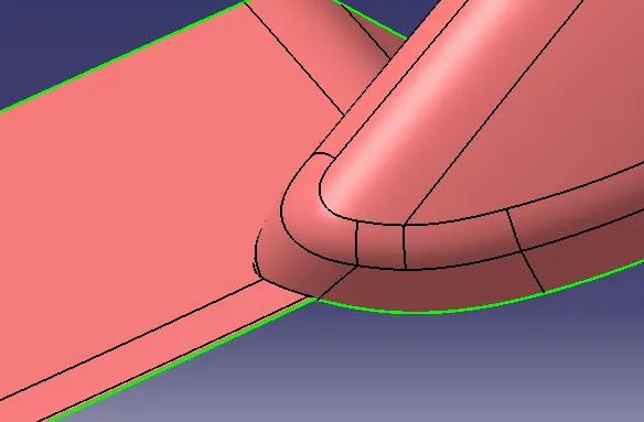
CLASS-A DRAFT ANALYSIS;
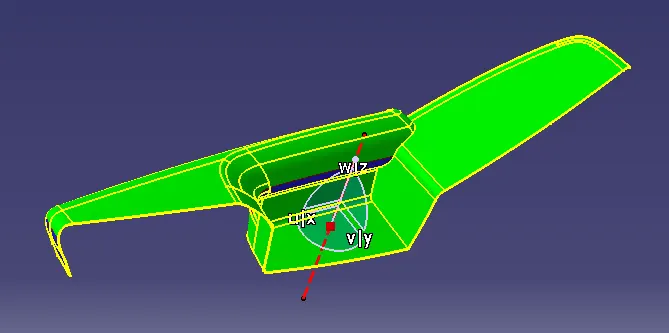
CLASS-B SURFACE;
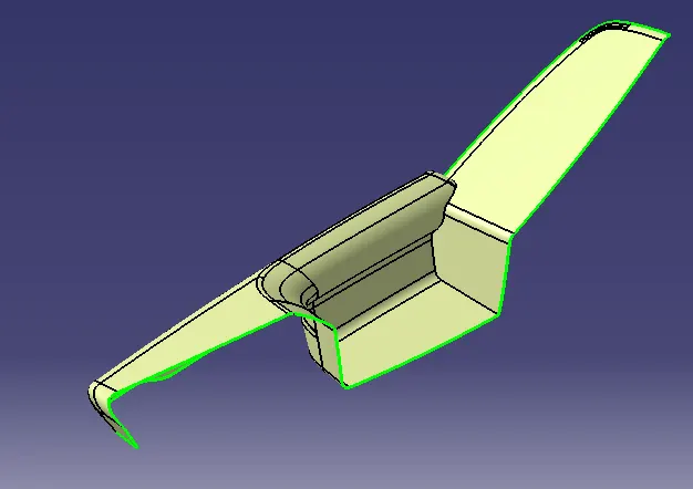
CLASS-C SURFACE;
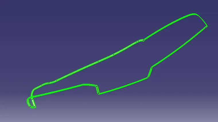
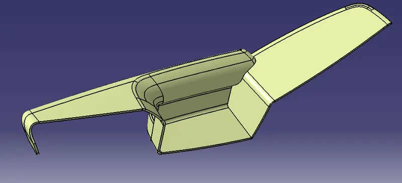
FINAL COMPONENT;
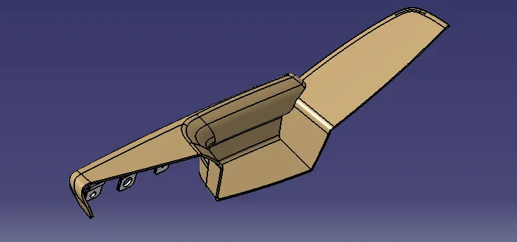
FINAL COMPONENT DRAFT ANALYSIS;
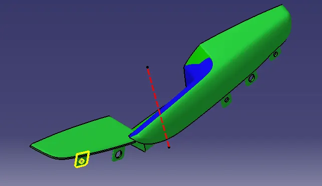
BOTTLE HOLDER
CLASS-A SURFACE;
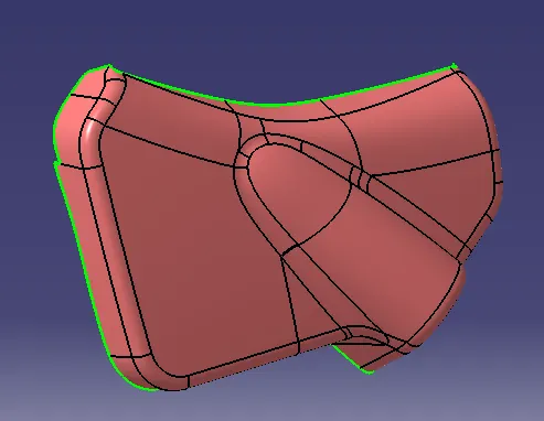
CLASS-A DRAFT ANALYSIS;
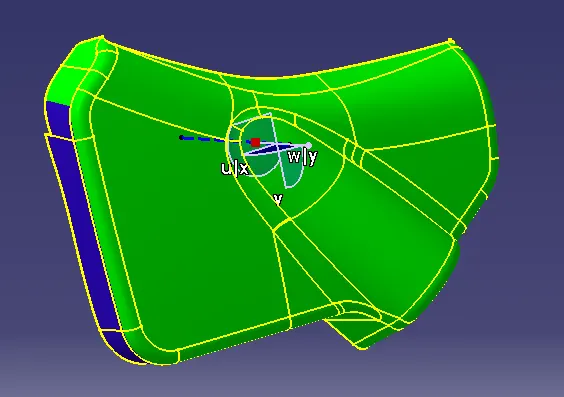
CLASS-B SURAFCE;
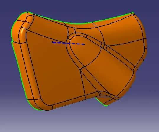
CLASS-C SURFACE;
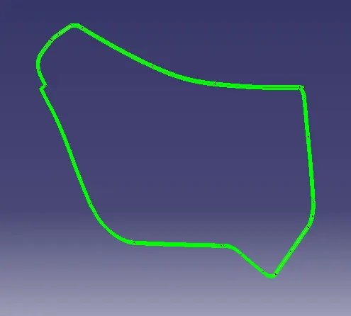
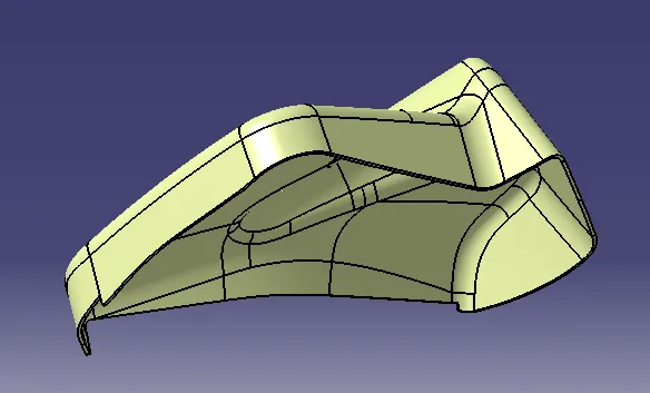
FINAL COMPONENT;
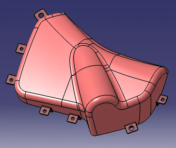
FINAL COMPONENT DRAFT ANALYSIS;
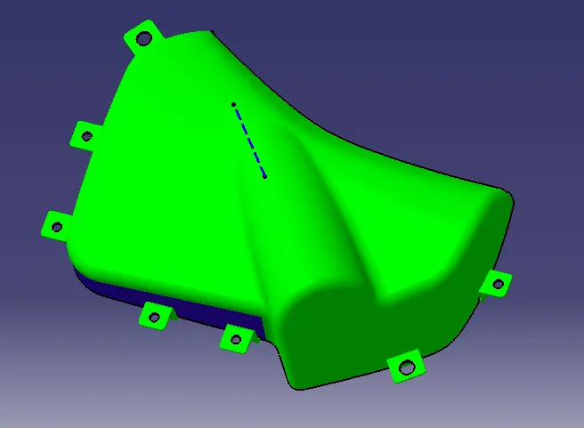
LOWER SUBSTRACT
CLASS-A SURFACE;
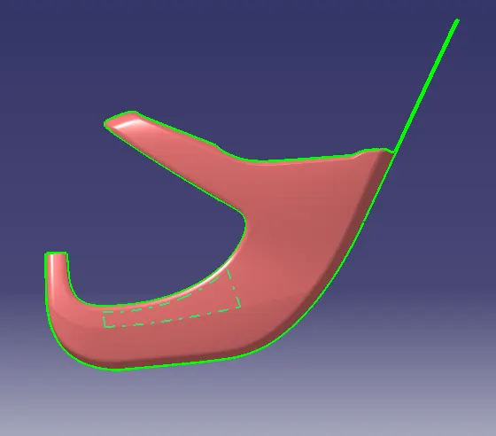
CLASS-A DRAFT ANALYSIS;
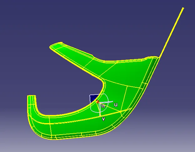
CLASS-B SURFACE;
CLASS-C SURFACE;
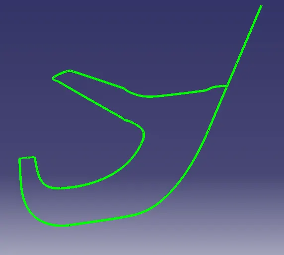
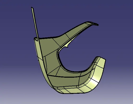
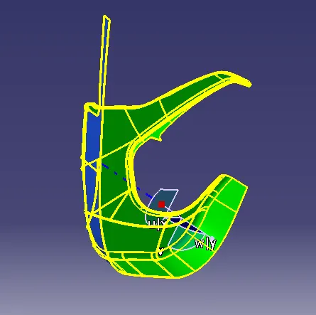
SOLID MODEL DRAFT ANALYSIS;
FINAL COMPONENT;
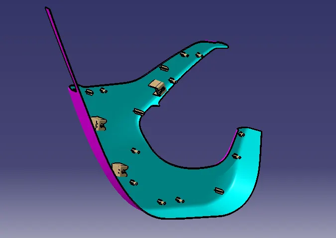
FINAL COMPONENT DRAFT ANALYSIS;
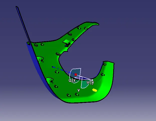
MAP POCKET
CLASS-A SURFACE;
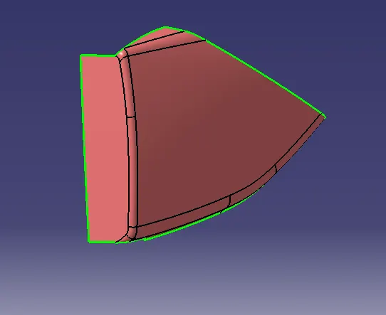
CLASS-A DRAFT ANALYSIS;
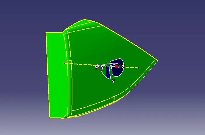
CLASS-B SURAFCE;
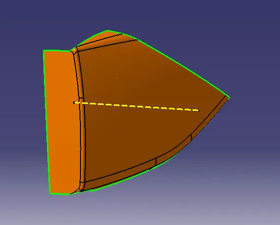
CLASS-C SURFACE;
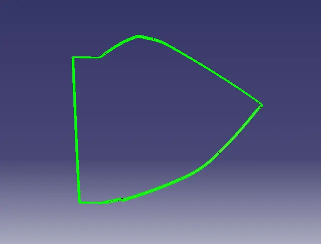
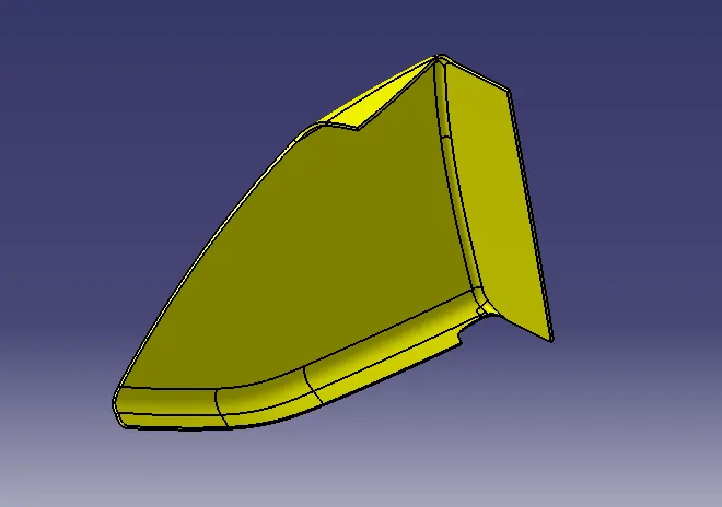
FINAL COMPONENT;
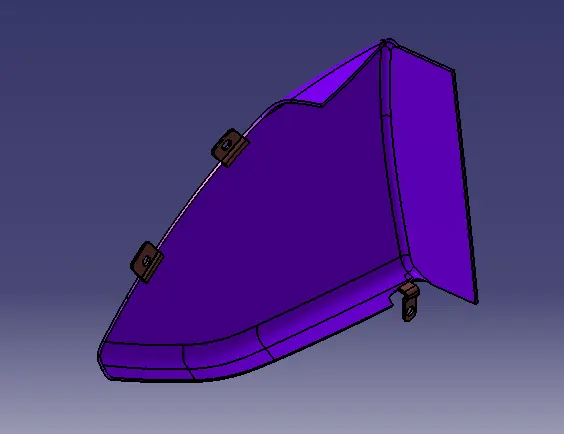
FINAL COMPONENT DRAFT ANALYSIS;
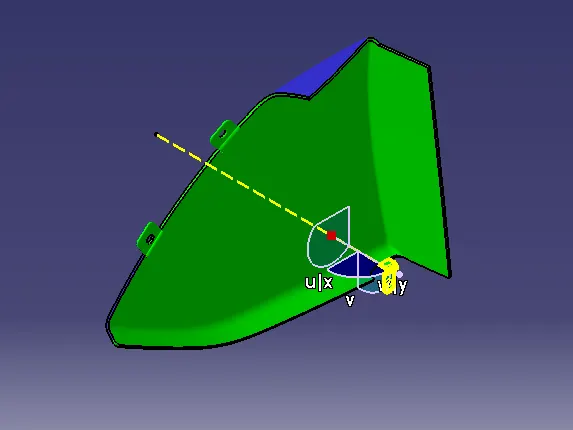
PUSH PIN
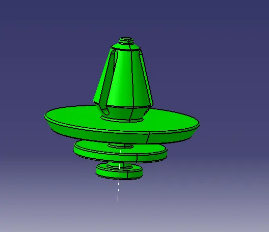
PUSH PIN WITH DOG HOUSE;
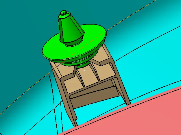
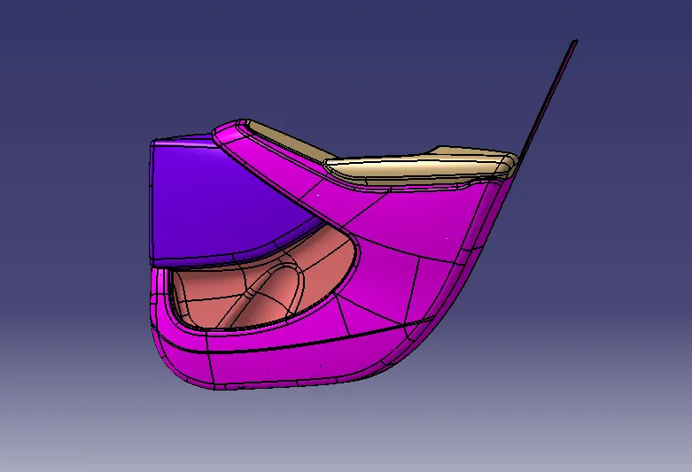
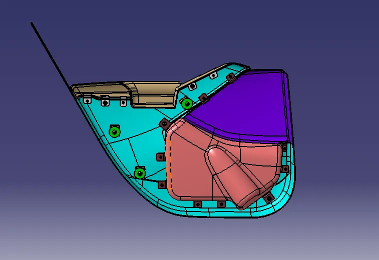
FINAL ASSEMBLY
CONCLUSION;
From this project I have leraned how to create CAD model for plastics parts by considering design rule. By doing this project on Catia V5 , I get very well familiar with part workbench ,surface workbench , Assembly workbench. Also I get confidence in handling different features of all workbenches. Along with this , I get idea of how to design a part by considering manufacturing and assembly aspect.