Week 12- Final project
Objective:
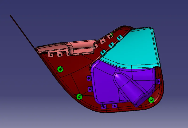
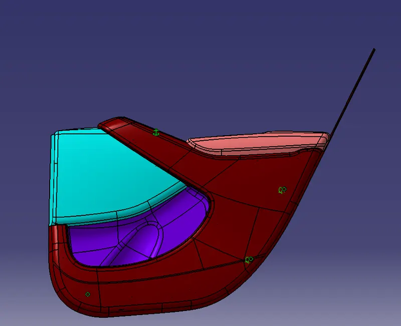
- a) Creation of side door trim panel from given class A surface. Apply thickness to it and use attachment features.
- b) Creation of flanges and heat stakes from given master sections.
- c) Creation of dog house and various attachment features using industry standards.
- d) Performing draft analysis and ensuring the features and surfaces clear it.
The main components of interior door panel of a car consists of the following parts .
1) Arm rest
2) Map pocket
3) Bottle Holder
4) Lower substrate
Tooling Axis Creation
- The next step is to create the tooling axis for the part which will determine the direction in which the core and cavity of the mould will move.
- Designer must ensure that all holes and slots are covered in the main tooling and thus side core must be avoided whenever possible
- After analysing visually for the best possible tooling axis, an axis system is created on the centre of one of the surfaces of the lower substrate.
- First a dummy tooling axis is drawn along the Y direction with the axis system and the centre point as reference
- If the draft analysis is cleared with the dummy tooling axis then it is considered as our main tooling axis.
Draft Analysis
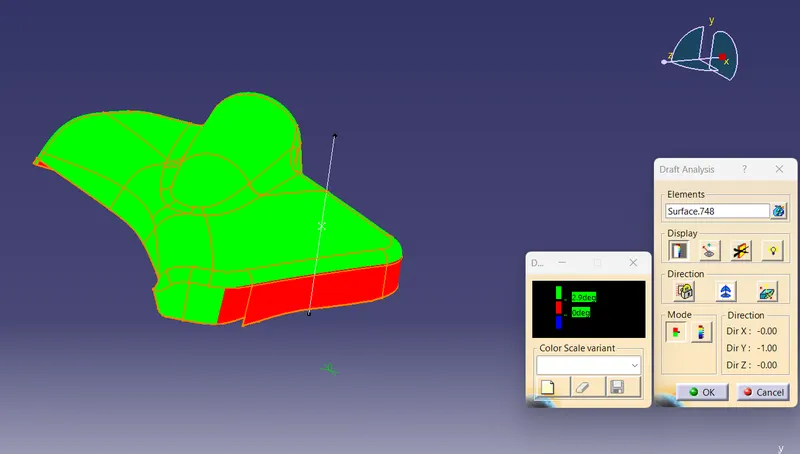
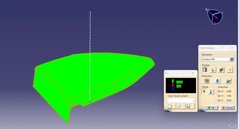
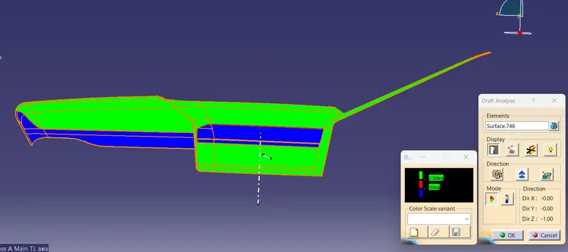
- Draft analysis is done on the class a surface after the tooling axis has been obtained
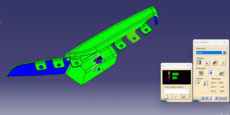
- The part must have a minimum draft angle of 3 degrees on all the tapered faces
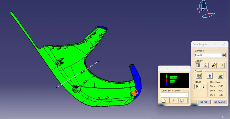
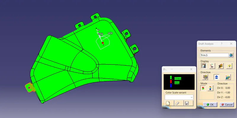
- Using the feature draft analysis tool and the compass the part surface is validated for the minimum draft criteria
- It is very important to validate the tooling axis for the class A surface since it will be helpful in creating the class C surface.
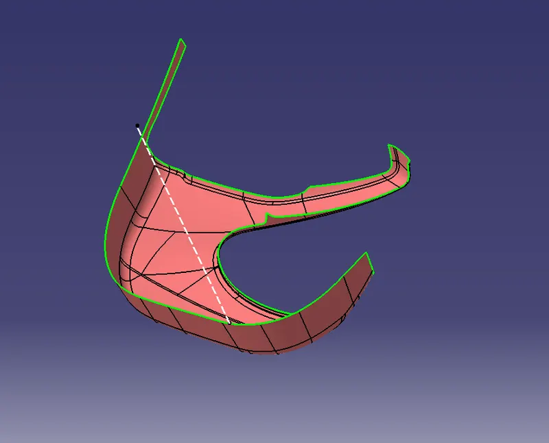
Tooling Axis - Lower Substrate
- Extract a surface, Create a point at the surface, then a line is created in the Y direction, which is the tooling axis.
Draft Analysis - Lower Substrate
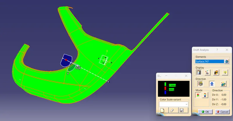
Some parts of Class A are not clearing the draft analysis due to the Class A problem.
Tooling Axis - Bottle Holder
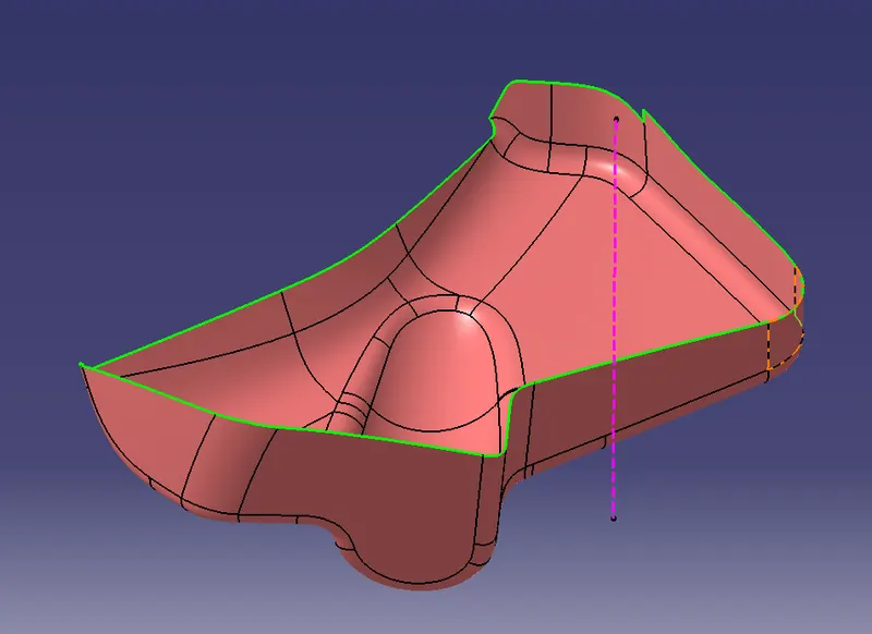
Draft Analysis - Bottle Holder
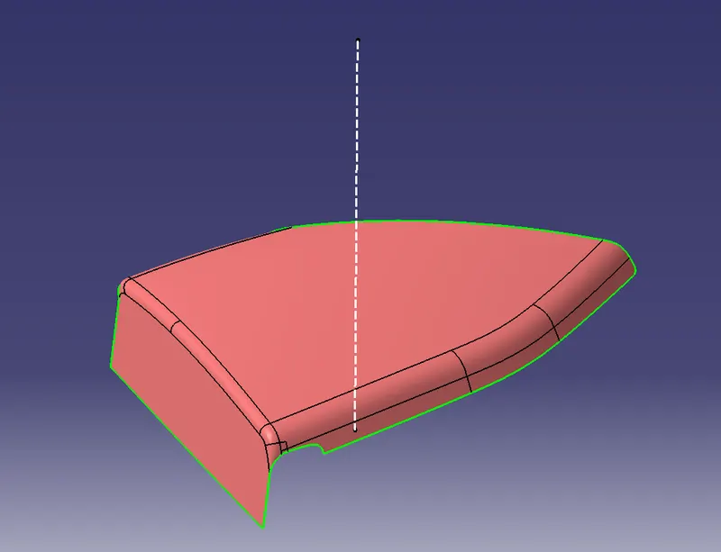
Tooling Axis - Map Pocket
Draft Analysis -Map Pocket
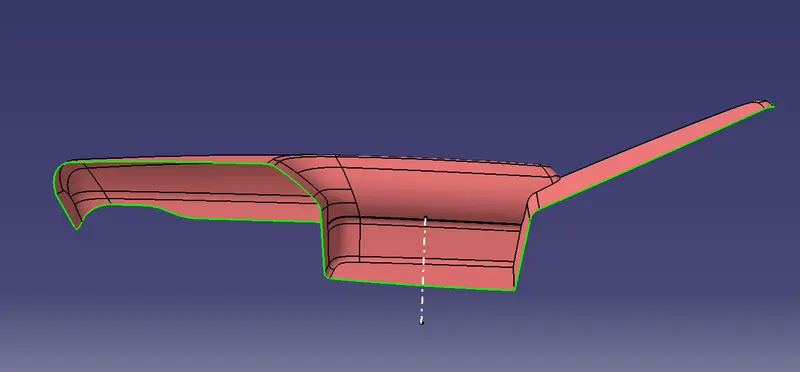
Main Tooling Axis - Arm Rest
Main tool axis is created along the Z direction.
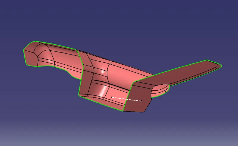
Side Core Axis - Arm Rest
Side core axis is created along the Y direction.
Draft Analysis -Armrest
Creation of Class B Surface
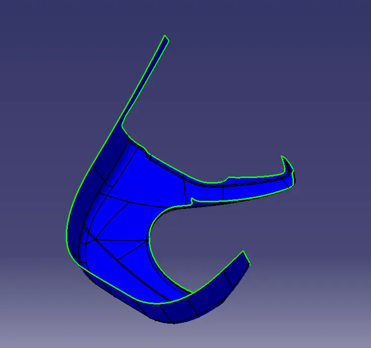
- Insert a new gemeotrical set.Measure the value of thickness in master section.The value is 2.5mm
- Offset the class A surface to 2.5mm.
- Check all the sub elements are formed if not try to fix it locally.
Class B Lower substrate
Class B Bottle Holder
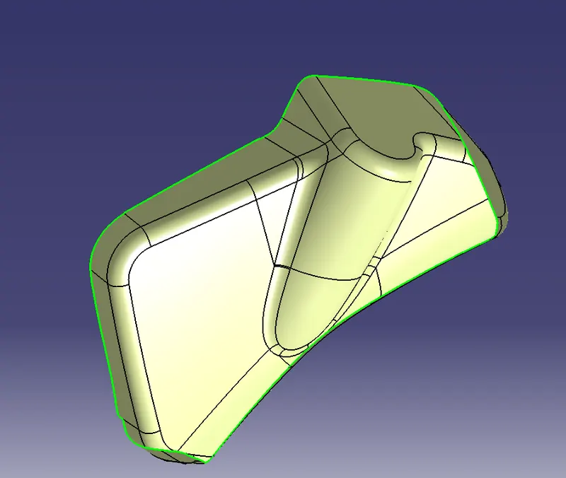
Class B Map Pocket
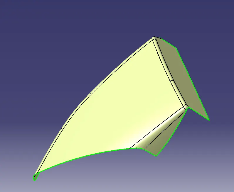
Class B Arm Rest
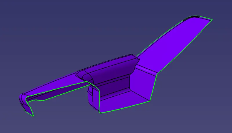
Class C
To make class C surface use sweep command to create a new surface an angle with respect to a surface. This angle is dependant on draft angle for free edges and ususally 90 degree for mating surfaces. In areas where sweep is not possible , use Multi section surface to create a new surface. Join all surfaces to obtain C surface.
Class C Lower Substrate
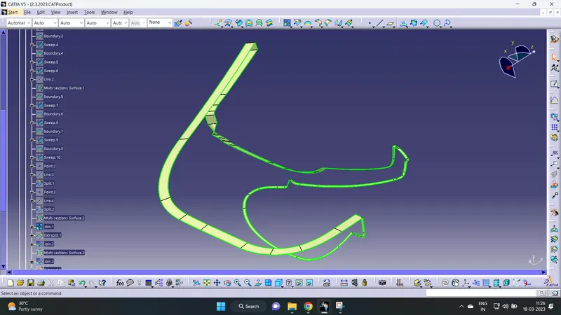
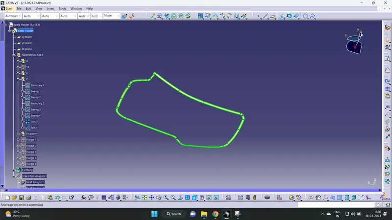
Class C Bottle Holder
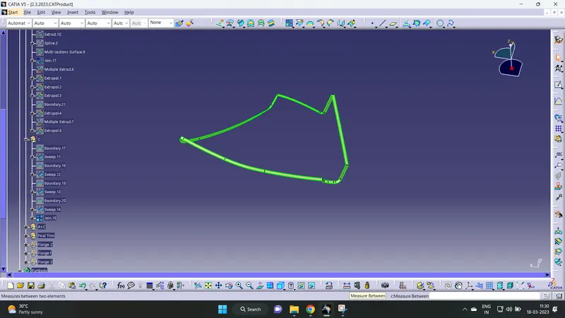
Class C Map Pocket
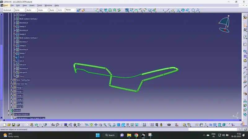
Class C Arm Rest
Creation of Closed Surface
Use trim or join option to join Class A and Class C. Use trim option to join above trim with class B. Similarly closed body was obtained for all other parts. Using Closed Surface command in part design, a solid body is created.
B Side features on lower substrate
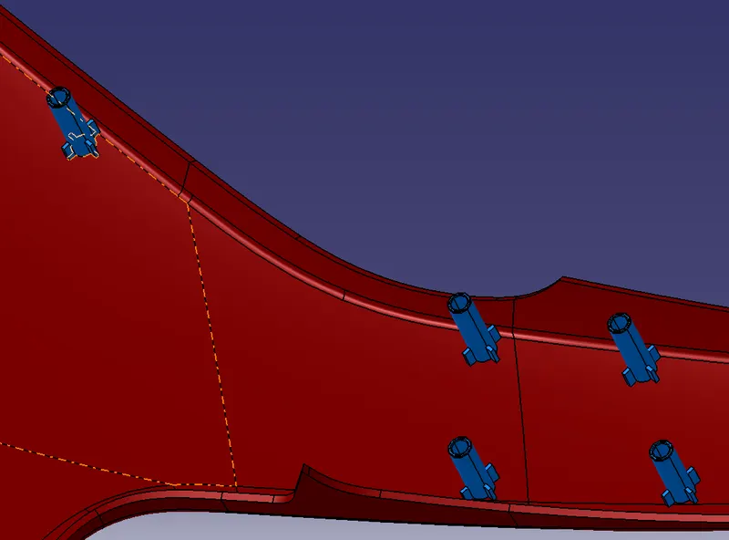
Heat Stakes
Heatstakes is known as thermoplastic staking is the process of joining two dissimilar metals together
- Extract the surface that we going to create heat stake
- Use positiioned sketch and draw a heat stakes sketch
- Pad the heat stakes.
- Give draft of 0.5deg
- Give edge fillet of 0.25mm top edges
- Take multilple extract of inner edge of the lower substrate and offset the distance as in the master section for obtaining thge position of other heat stakes.
- Add rib to the heat stakes.
- Minimum distance between heat stakes should be 50mm.
- Translate the Heat stakes to wherever required
- Union trim heat stakes to lower substrate.
Locators
- Extract the surface that we going to create locator
- Use positiioned sketch and draw a locator sketch.
- Locators height should be more than the heat stakes.
- Use pad commands for the sketch to till we required
- Draft the locator for minimum of 0.5 degree
- Add fillet 0.5mm on all faces
- Translate locators to wherever required.
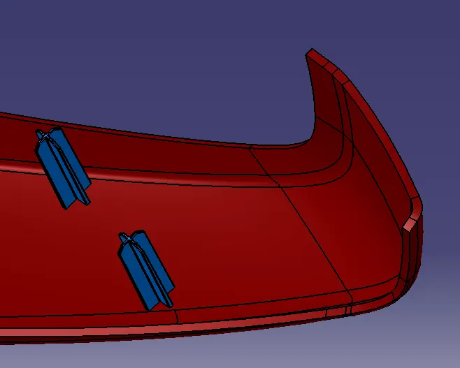
Doghouse
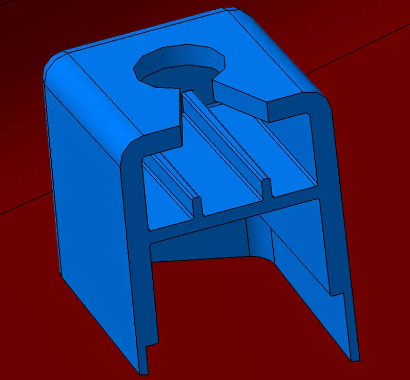
- The two main purposes of a dog house are to avoid sink marks and to house various other engineering features like screw boss, locators, push clips etc.
- Doghouse wall thickness at the intersection of the part wall (C) should be 40% or less than the main wall stock (T).
- The height of ( B ) should be between 3.0 – 6.0 mm
- Outer surface of dog house must have a draft angle of 3 degrees
- Inner surface of dog house must have a draft angle of 0.5 degree
- Add ribs and hole for push pin assembly.
- Translate this doghouse where ever required.
- Union trim with Lowersubstrate Closed body.
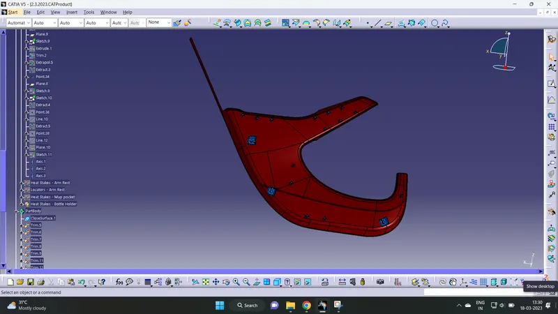
Flange Creation
Flanges are created for attachment of heatstakes and locators at lower substrate to the neighbouring parts Bottle Holder, Map pocket and Arrm Rest.
- Take intersection of C Surface of the part where the flange has to be created.
- Draw a random line and coincide with this intersection. Constraint this line with angle as in master section.
- Sweep this line through the multiple extract along the C surface edge for creating vertical side of flange.
- Extrude a flat line patrallel to X axis for top surface.
- Trim these two sufaces.
- Thicken the trimmed surface profile in part design.
- Create a flat surface parallel to Y axis and offset in both sides for cutting the soild body.
- Give draft of 0.5deg for the flange edges and edge fillet as in the master section.
- Create a sketch and hole in the flange with 0.5mm clearance between the heat stakes and Flange hole.
- Give draft to the hole created.
- For creating horizontal portion of the flange in curved area, create a line from the multiple extract edges and give us support while extruding.
- Union trim the flange to solid body.
Flanges on Arm Rest
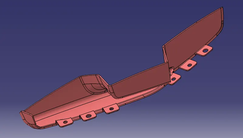
Flanges on Map pocket
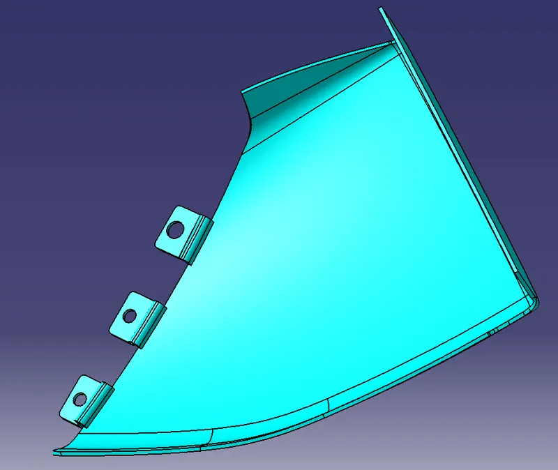
Flanges on Bottle Holder
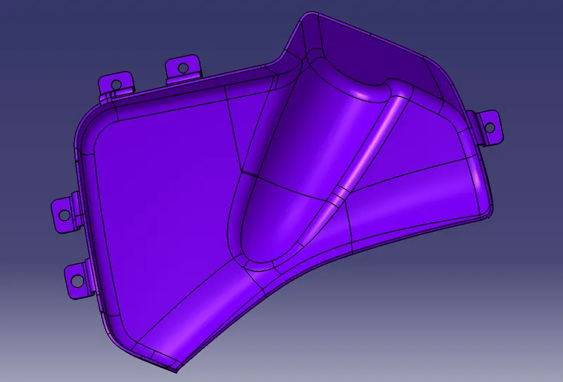
Draft Analysis Solid body
Lower Substrate
Bottle Holder
Map Pocket
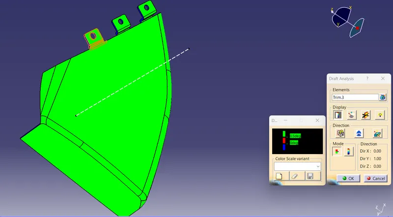
Arm Rest
Main Tooling Axis
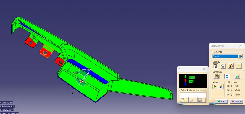
Side Core Axis
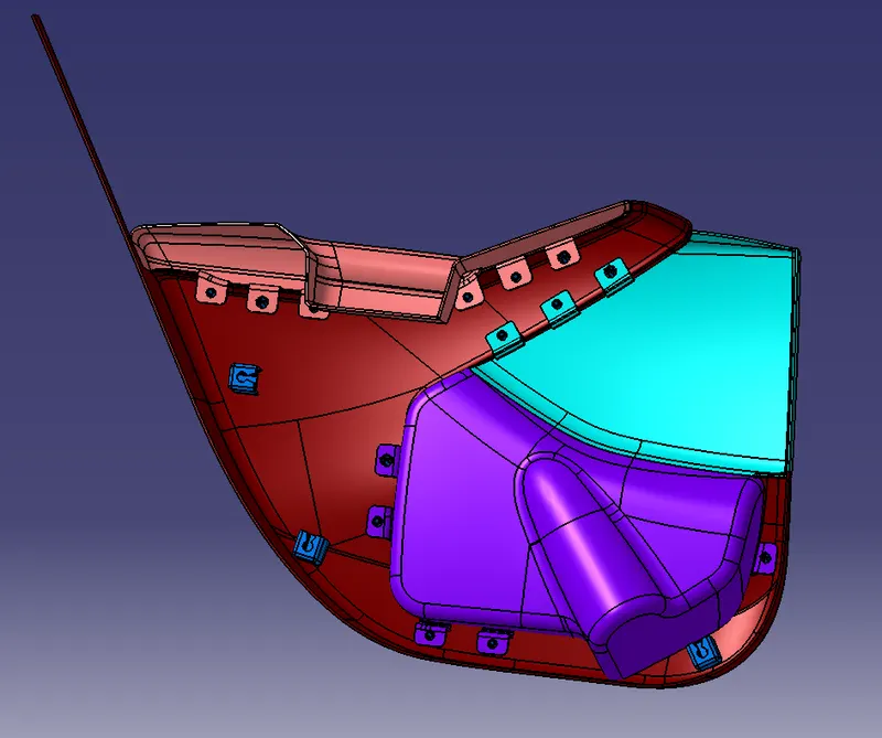
Push pin assembly
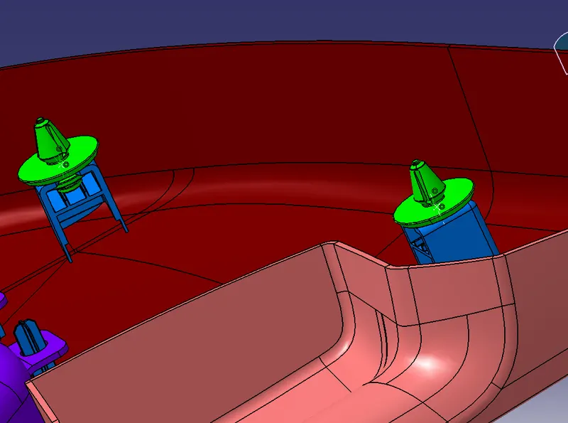
The final assembly of the door trim involved the insertion of the push clips into the respective dog house slots. Fix the lower substrate using Fix constraint. Using the dog house central axis and the axis of the push pin coincident relation was given. After which, a point is created on the puspin circle and doghouse center hole slot, and using offset constraint 0mm assembly is done.
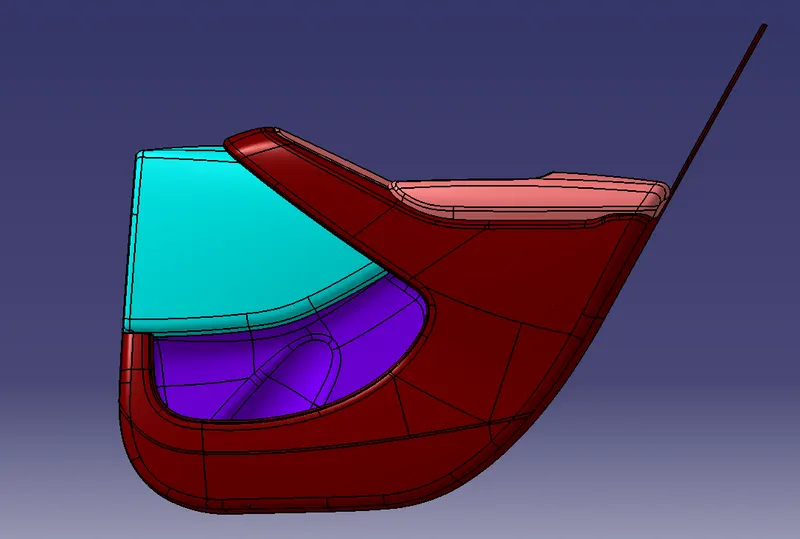
Final output