Week 12- Final project
FINAL PROJECT
PROJECT TITTLE: DEVELOPMENT OF DOOR TRIM PANEL
SOFTWARE USED: CATIA-V5
SUBMITED TO: SKILL-LYNC
SUBMITED BY: K.MADHAN
AIM:
To create a solid body of Side Door plastic trim including the engineering features using catia v5 tool using given A class surface and master section and adding thickness.
INTRODUCTION :
Side Door Plastic Trim
An interior component attached to the inner side of the door. This product does more than merely improve the appearance of the vehicle interior. Rather, it is a vital module component that creates a more comfortable interior by providing a variety of accouterments and functions.
OVERVIEW DESIGN LIFE CYCLE AUTOMOTIVE INDUSTRY
Product Development Process:
- Concept/ideation
This is the concept and ideation stage during which a product’s functional and performance requirements can be defined along with buyer personas or ‘the voice of the customer’. Customer requirements and innovative functionality design ideas are floated and explored freely to find compelling potential solutions that answer an identified market need.
- Feasibility study and design planning
The feasibility phase gives management an opportunity to evaluate a project’s potential success, reviewing and refining the business case from various angles. During this phase, the project team reviews product design concepts. They then select the design that best fulfils the previously defined user requirements. Now, the detailed, exhaustive project requirements are assembled that will guide the design and development phase.
- Design and development
In this phase, formal engineering specifications are created. Verification and validation plans are developed for the future. These are the final quality checks that will systematically determine that all agreed deliverables are present and working in the end product. The product is then developed against the designs, with regular checks made throughout the process to assess and mitigate the risk of its failure for the end-user and the project itself.
- Testing & verification
Comprehensive testing of the final product takes place to evaluate the robustness of the design and its ability to meet customer and performance requirements. Verification takes place against the design requirements identified in stage 2.
- Validation & collateral production
Validation takes place against the customer needs that have been identified at the ideation stage. Collateral is finalised and prepared to support the manufacture and launch phase.
- Manufacture/launch
Plans, specs and other relevant documentation are transferred to manufacture for production, or software products and updates are released to customers. Marketing and launch plans are finalised and activated. Software products are released to customers electronically as updates or downloads.
- Improvement
The new product becomes part of the company’s portfolio. Ongoing product management ensures the product is subject to continuous upgrades and improvement. CAPA processes are in place to feed into these actions.
The Stages of Design Life Cycle are
Concept Sketches:
Concept sketches are rough idea of free hand sketch obtained through styling team and will be used to prepare the Model. It is usually done through pen and paper and through the painting software. This is will be used to generate the concept for preparing the model by incorporating various styles and information obtained through the stakeholders
Class A Creation:
After finalizing the concept the sketches are usually worked in software’s such as Autodesk Alias to create Class A Surface
Clay Modeling :
The Class A Surface is concurrently worked by clay modelers to brainstorm and benchmark the styling of the product and later the Concept is validated by bringing up a rough clay model and then it is passed on to the Design team for the preparation of New Product Design (NPD) CAD.
NPD CAD :
This where the development of surfaces to parts in CAD kick off and Design engineers involvement is vital in this stage.
The Designers will work on the Input Class A surfaces which are validated from the Feasibility team
The procedure followed in creation of the plastic New Product Design are
- TOOLING AXIS CERATION
- B SURFACE CREATION
- C SURFACE CREATION
- CLOSED BODY CREATION
- DRAFT ANALYSIS
INPUT GIVEN:
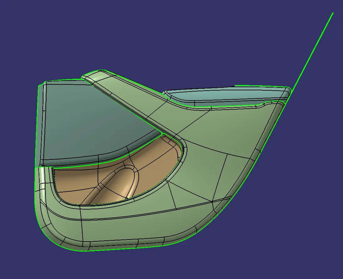
Design of Interior Door trim:
Interior Door trim consists of four components
1)Lower Substrate
2)Bottle holder
3)Map Pocket
4)Door Arm Rest
2) A Class Surface
In automotive design, a class A surface is any of a set of freeform surfaces of high efficiency and quality. Although, strictly, it is nothing more than saying the surfaces have curvature and tangency alignment – to ideal aesthetical reflection quality, many people interpret class A surfaces to have G2 (or even G3) curvature continuity to one another. Class A surfacing is done using computer-aided industrial design applications. Class A surface modellers are also called "digital sculptors" in the industry. Industrial designers develop their design styling through the A-Surface, the physical surface the end user can feel, touch, see etc.
LOWER SUBSTRATE:
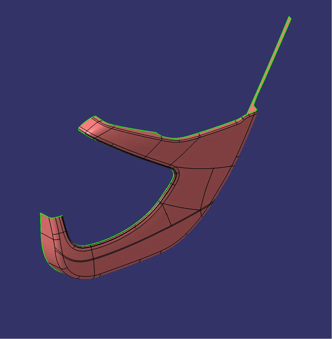
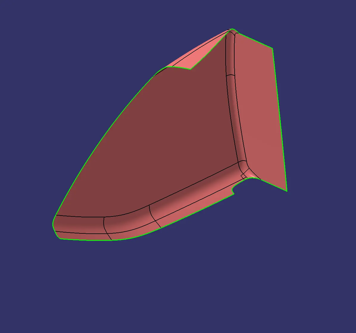
MAP POCKET:
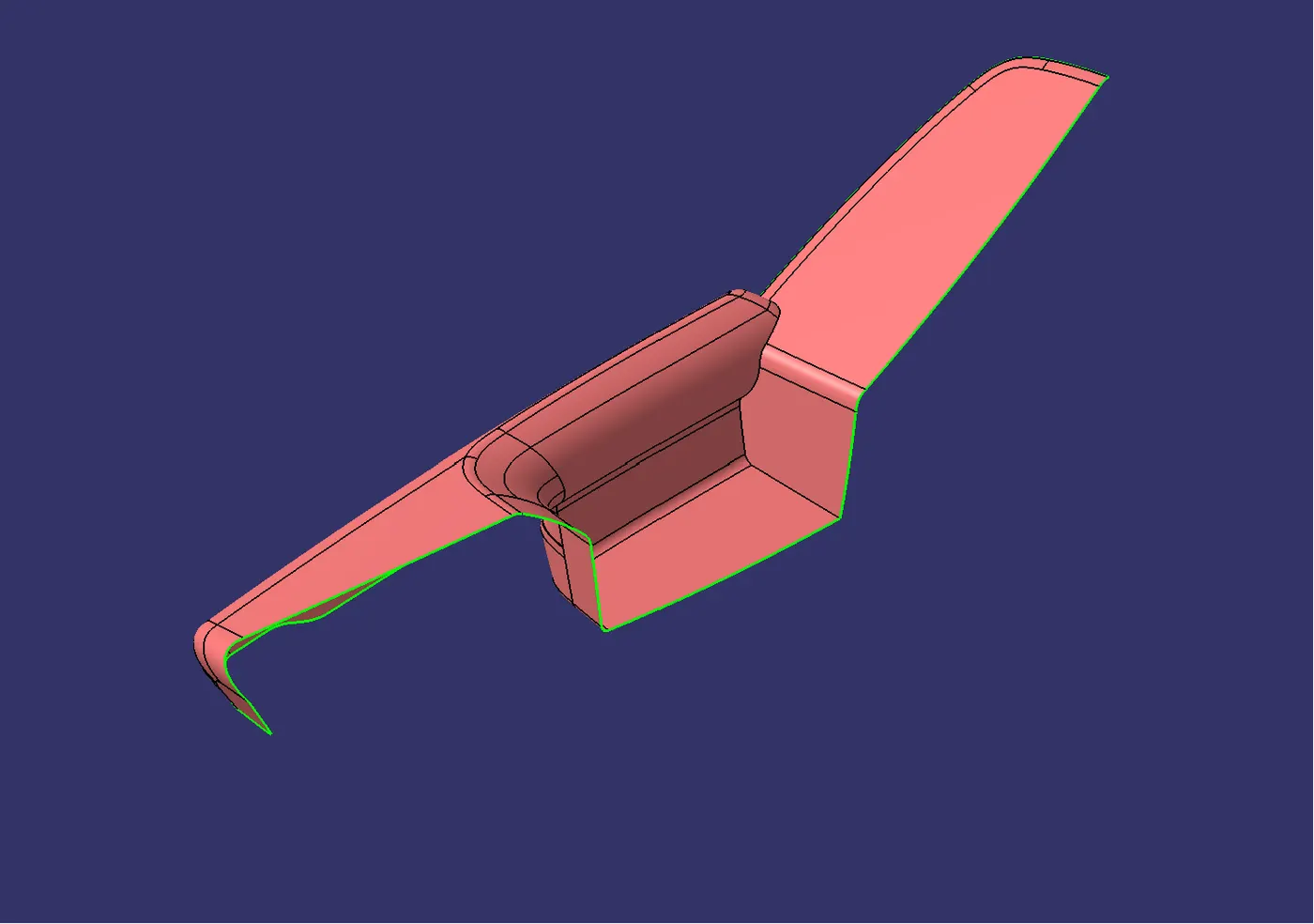
DOOR HARM REST:
BOTTLE HOLDER:
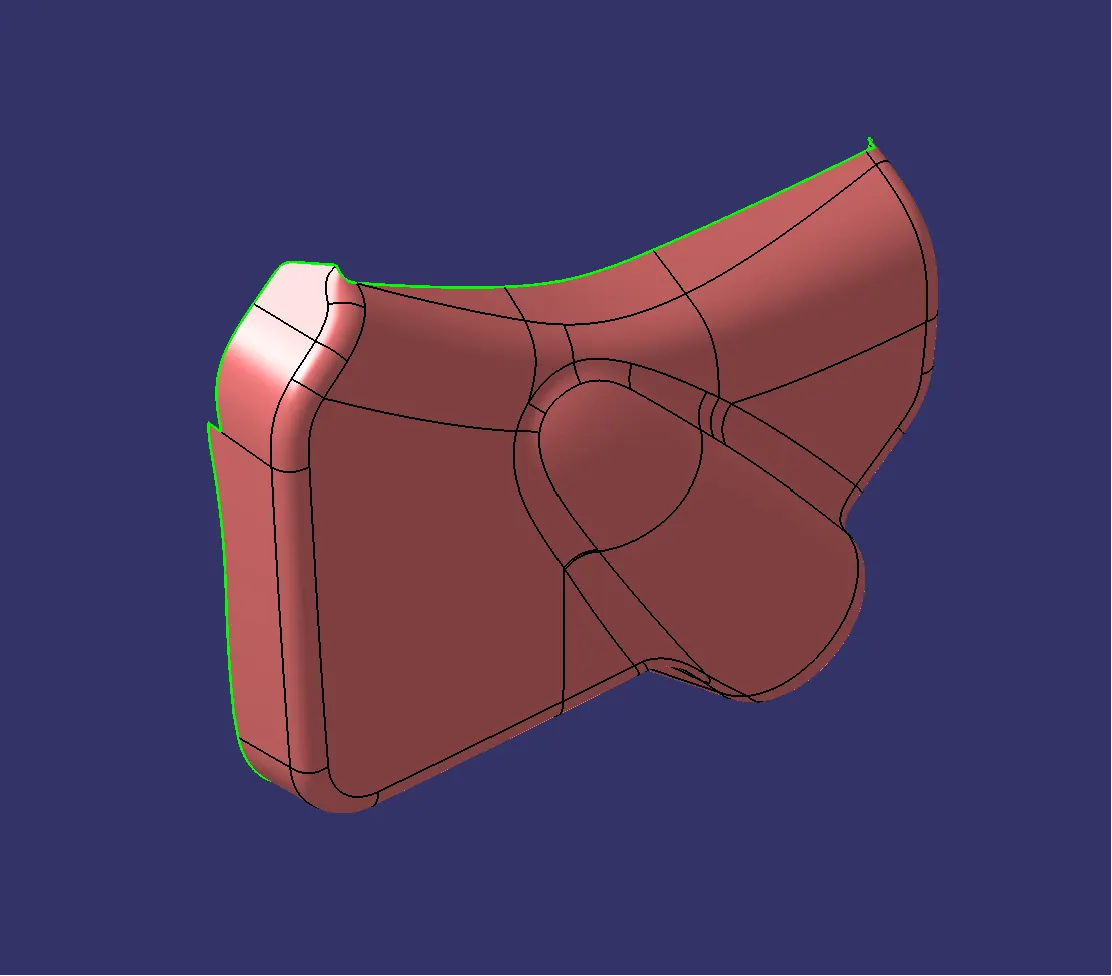
Tooling Axis
Tooling axis is nothing but the direction in which the core and cavity opens and closes. Design engineer works is to analyse the Class A surface and find out the best possible tooling direction keeping in mind all the draft angle is with respect to the tooling axis so that the component can be easily ejected from the moulds.
Door Arm Rest

Map Pocket
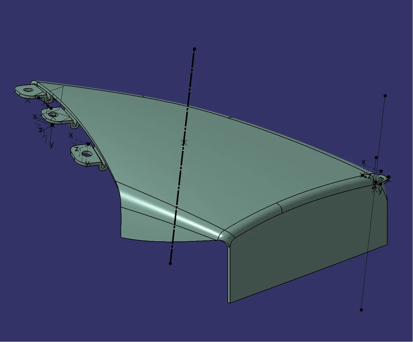
Lower Substrate
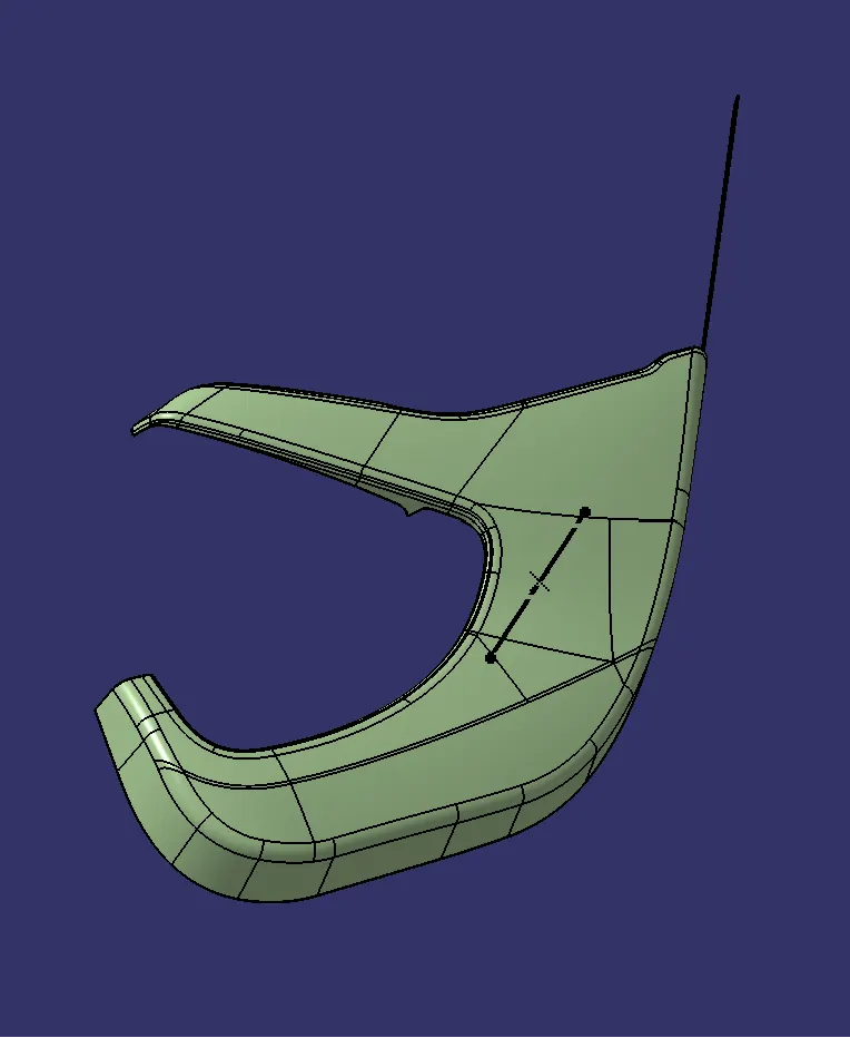
Bottle Holder
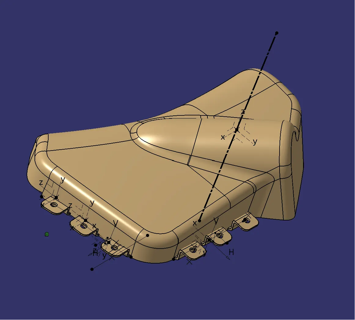
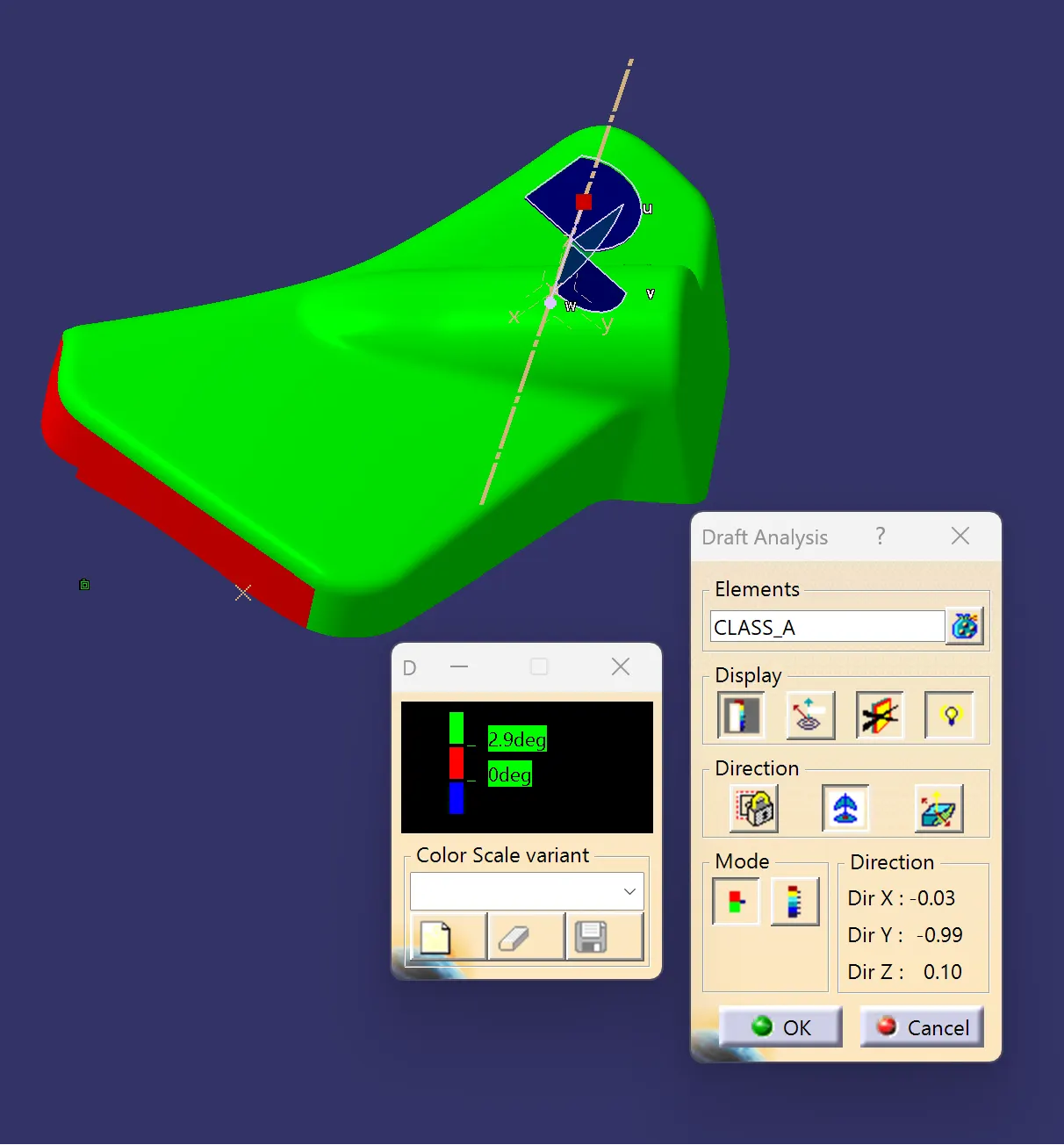
Draft Analysis
The Draft Analysis command enables you to detect if the part you drafted will be easily removed. This type of analysis is performed based on color ranges identifying zones on the analyzed element where the deviation from the draft direction at any point, corresponds to specified values.
Draft angles are very important in thermoforming product design. If the product is formed onto a female or negative mold, it shrinks away from the mold sidewalls. As a result, true female or negative products can be thermoformed with vertical walls having zero draft angles. Parts Cannot be ejected from the tool if it is at 90 degree surface.for the reason,A small Draft angle is to be provide for each and every surface s of the Component in order to easy removal of component from the moulds without any defects.Draft is the angle in which the part is tapered to aloow it to release.Most of the part require minimum 1/2 degree to 1 degree however 3 degrees are widely accepeted in plastic component design.Draft Analysis is the technique used to analise weather our designed product are manufacturable with required conditions or not.
DRAFT ANALYSIS OF CLASS A:
HARM REST:
ALONG MAIN TOOLING AXIS:
The draft analysis of above mentioned is have some class issues so at areas it doesent clear the draft tooling direction,so we it as minumum angle of deviation we can design the part.And by creating side core tooling axis we can manafacture the part.
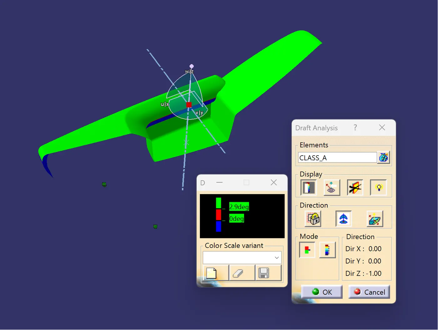
ALONG SIDE CORE TOOLING AXIS:
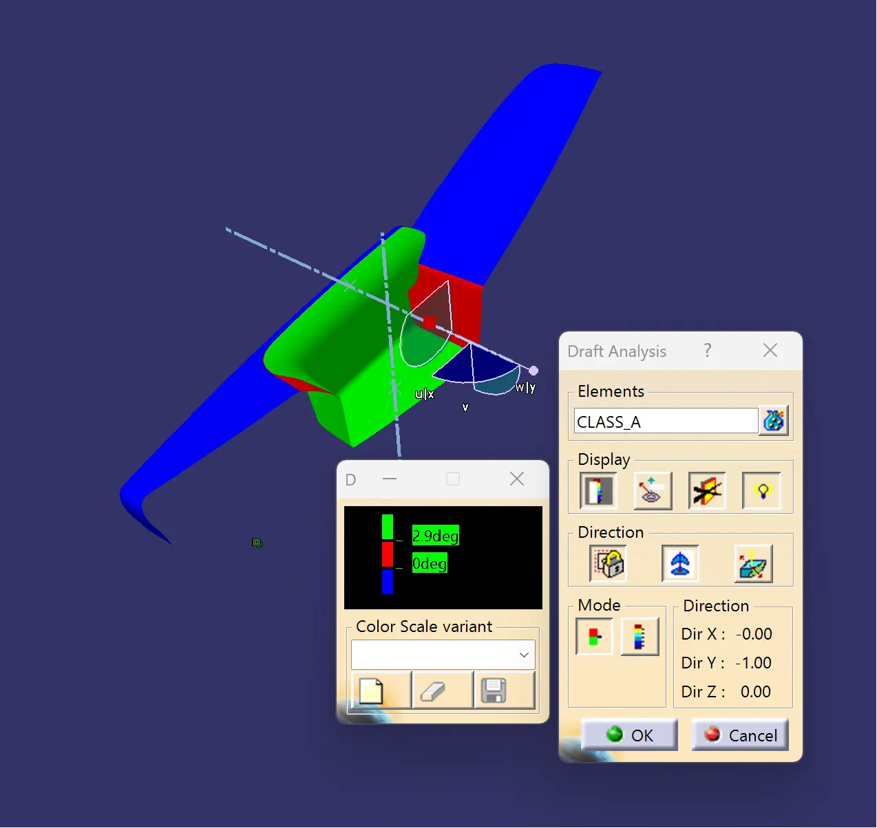
LOWE SUBSTRATE:
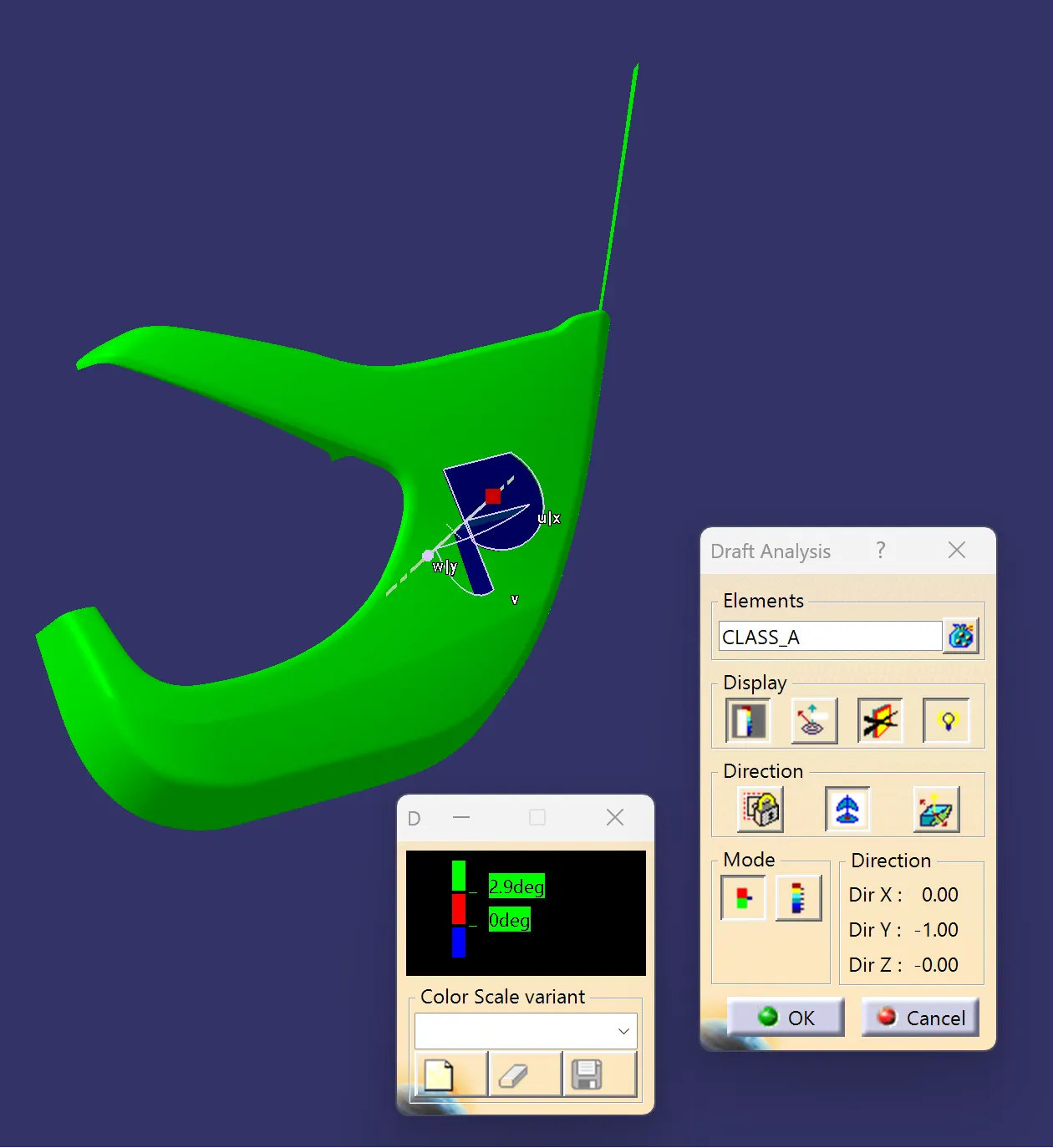
MAP POCKET:
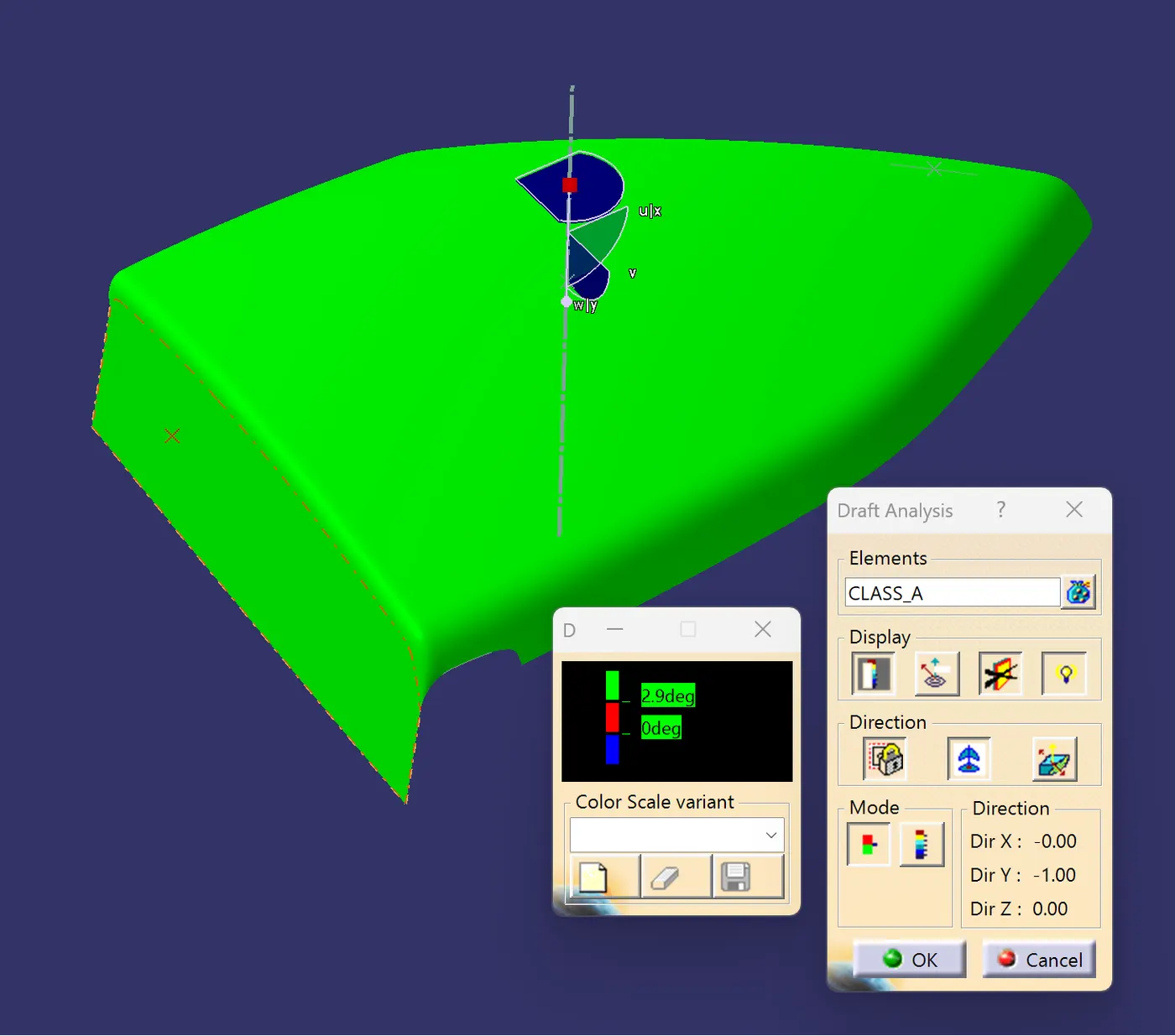
BOTTLE HOLDER:
The given class-A has some asthatic surface issues so it has some uncleared draf,even it has we design the part.
CLASS-B SURFACE CREATION:
WHAT IS CLASS-B SRFACE:
B' class surfaces can also be referred to as 'engineering surfaces. I have not personally heard of any surface being referred to as a 'C' type. generating visual quality surfaces. continuity. G3 is often sought on the more major block surfaces. G3 deals with curvature "acceleration", i.e. the rate of change of curvature across a boundary.
HOW TO CREATE THE CLASS-B SURFACE:
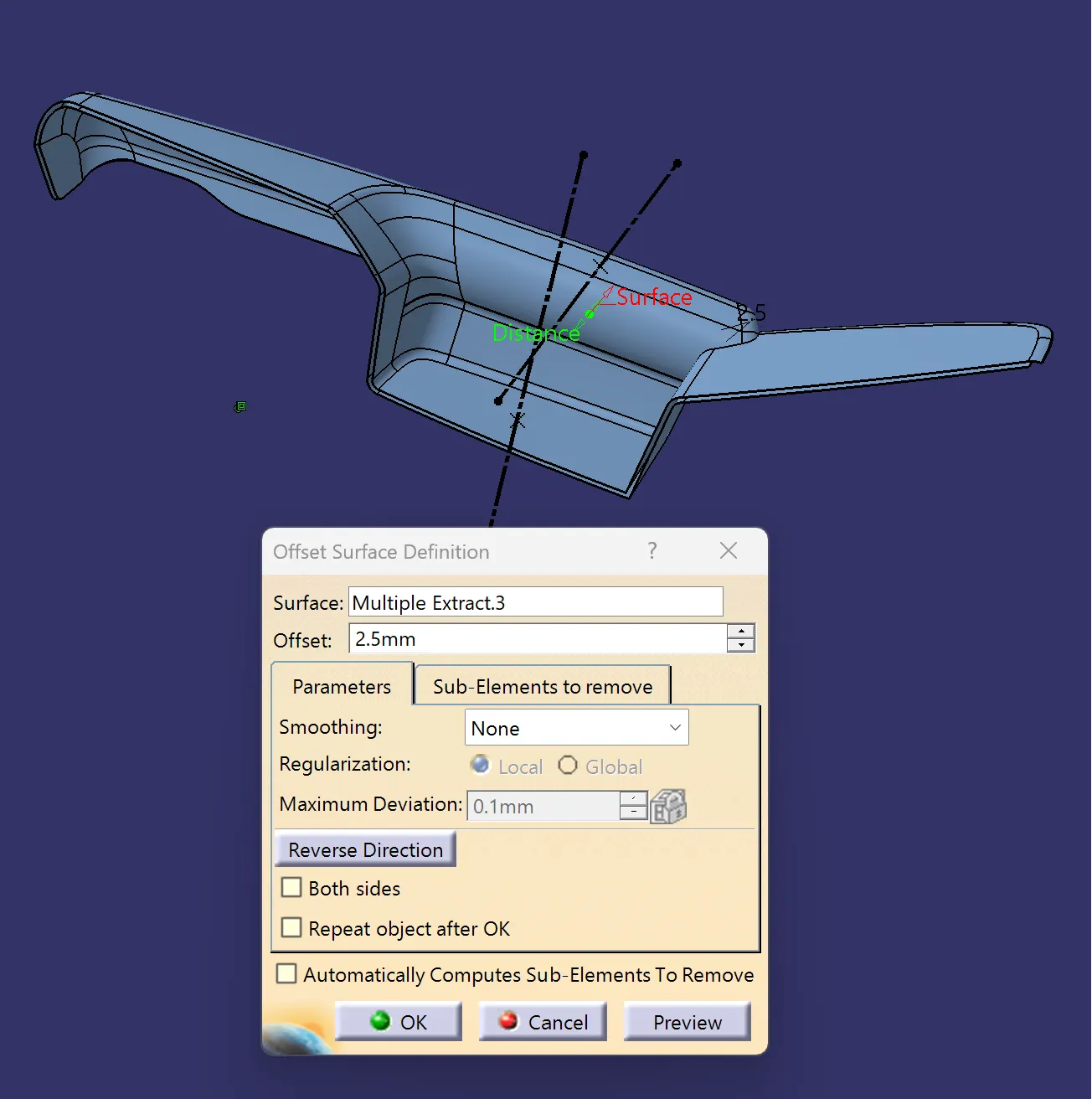
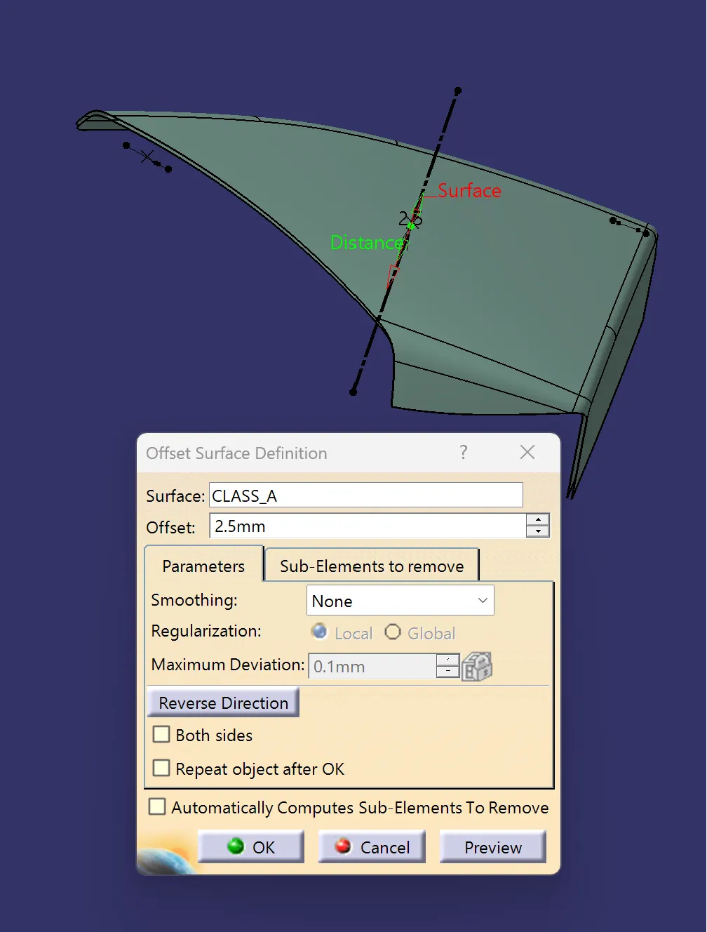
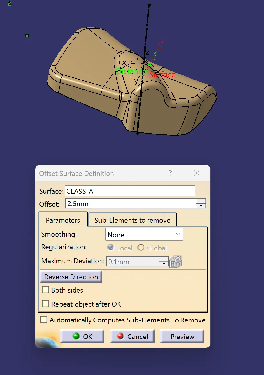
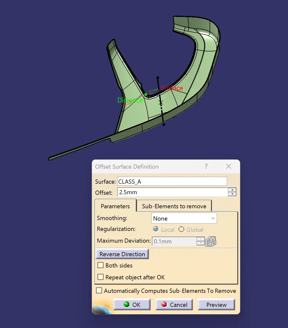
We need to offset class-A surface inti part thicknees of 2.5, then it has some surface discontinutity we need to repair the offseted class-B surface by using commands like multisection surface,sweep.
DOOR HARM REST:
MAP POCKET:
BOTTLE HOLDER:
LOWER SUBSRATE:
CLASS-C SURFACE CREATION:
WHAT IS CLASS-C SRFACE:
- A surface means visible surface.it will give styler.B surface means thickness of a part it is not visible it is inside part. c surface means A and B combined to give C surface
CLASS C SURFACE
create the surface with swept & multi section surfaces and rework the patches by using multisection surface.
LOWER SUBSTRATE:
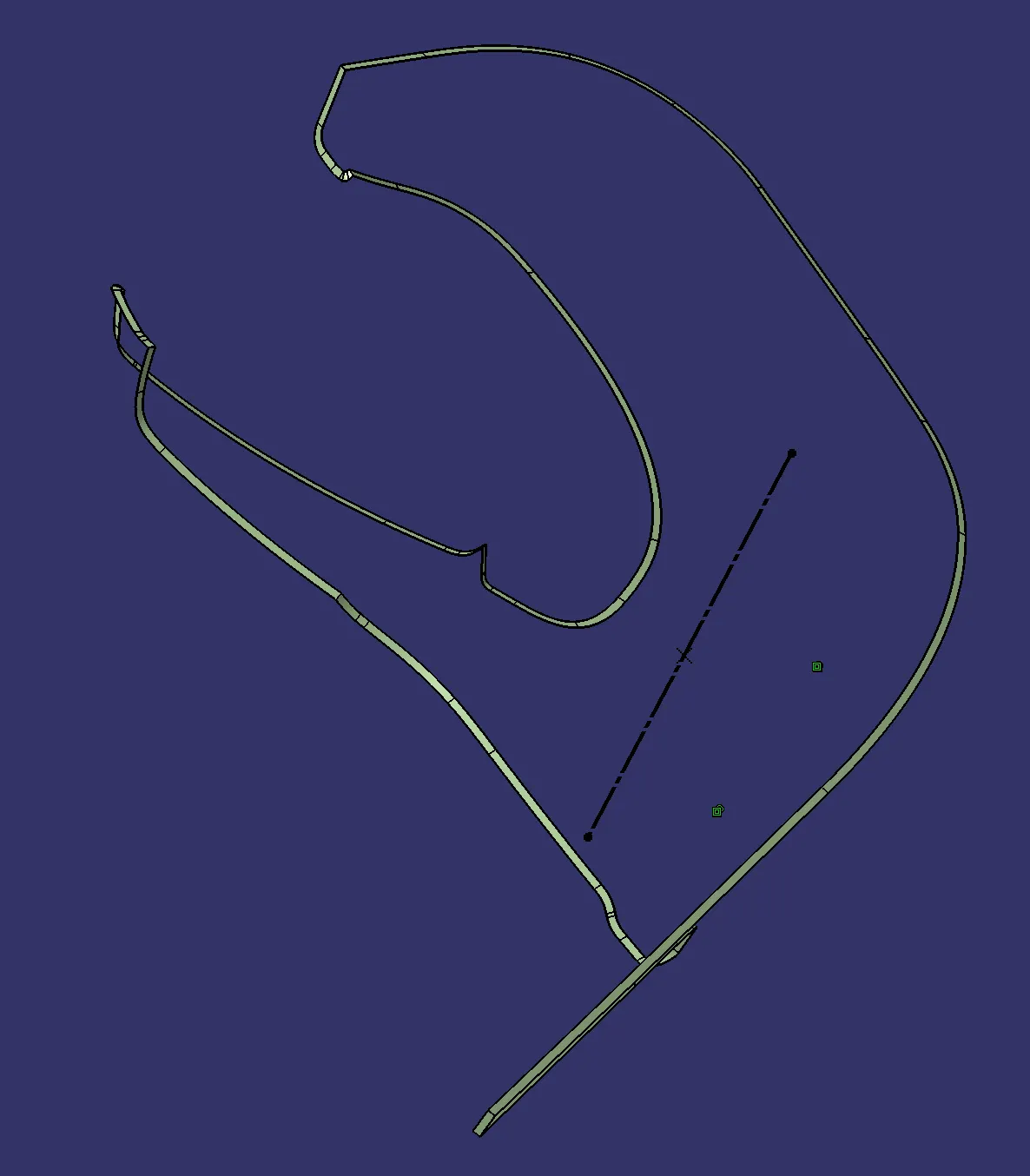
MAP POCKET:
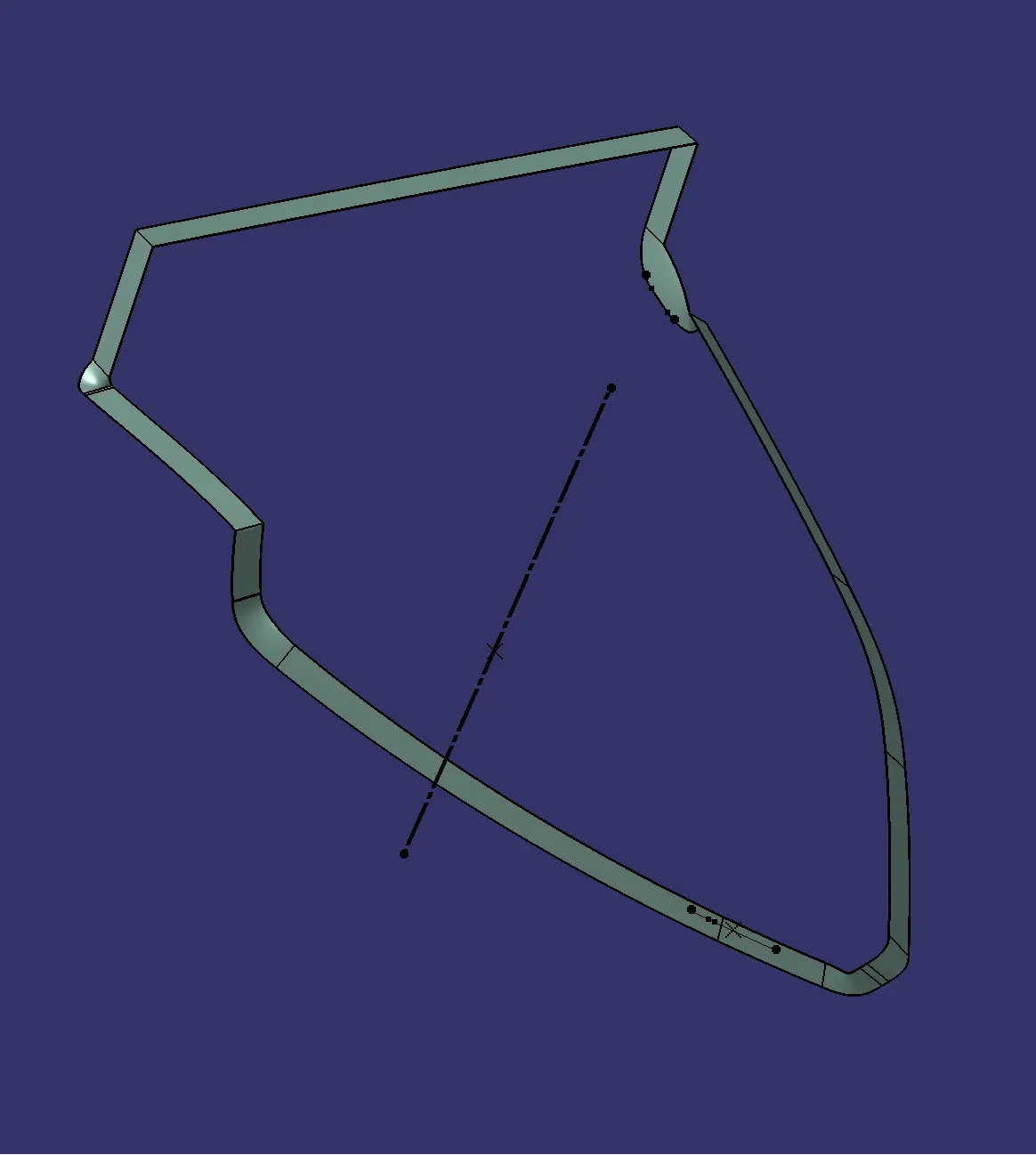
BOTTLE HOLDER:
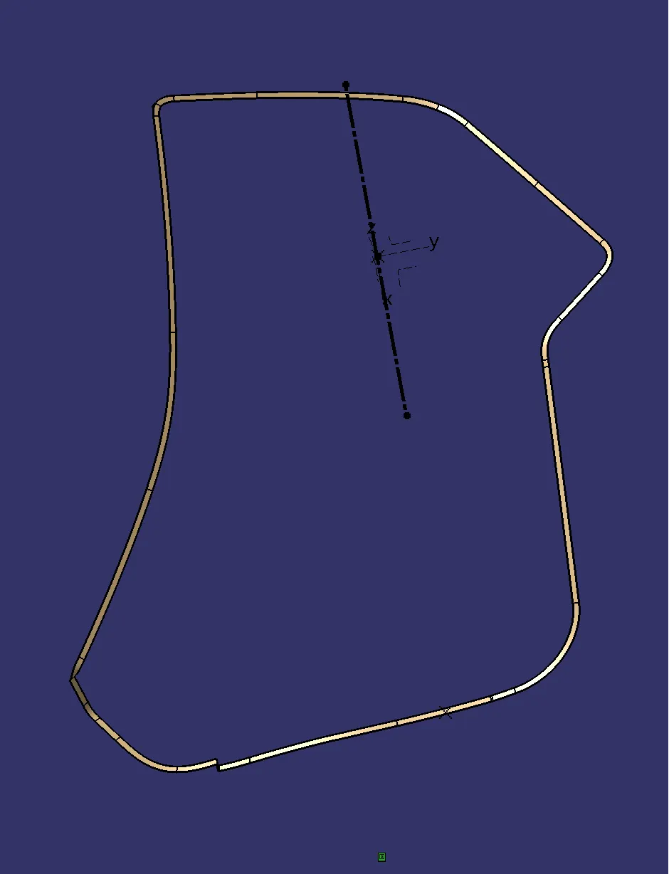
DOOR HARM REST:
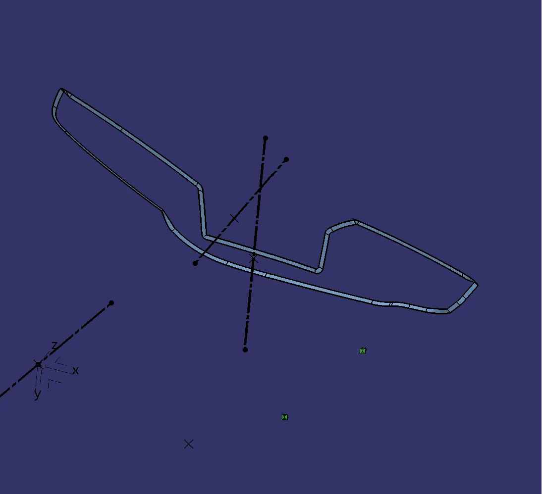
CLOSED SURFACE AND THICKEN COMMAND:
DOOR HARM REST:
MAP POCKET:
LOWER SUBSTRATE:
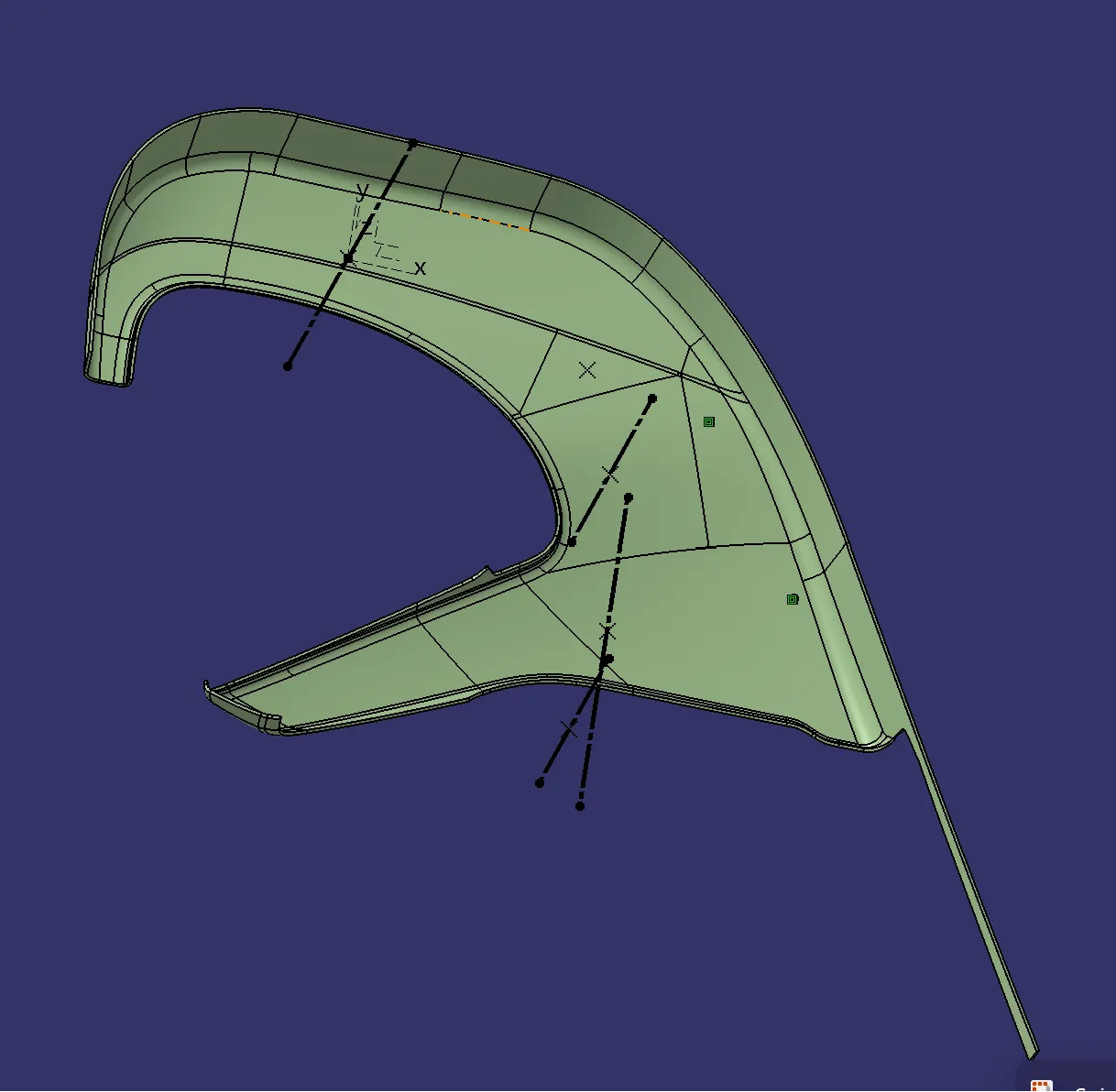
BOTTLE HOLDER:
DRAFT ANALYSIS OF CLOSED PARTBODY (WITH MINUMUM DRAFT ANGLE OF 3 DEGRE)
LOWE SUBSTRATE:
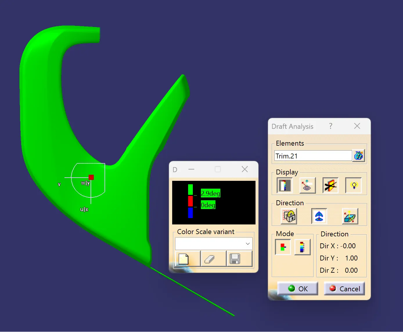
BOTTLE HOLDER:
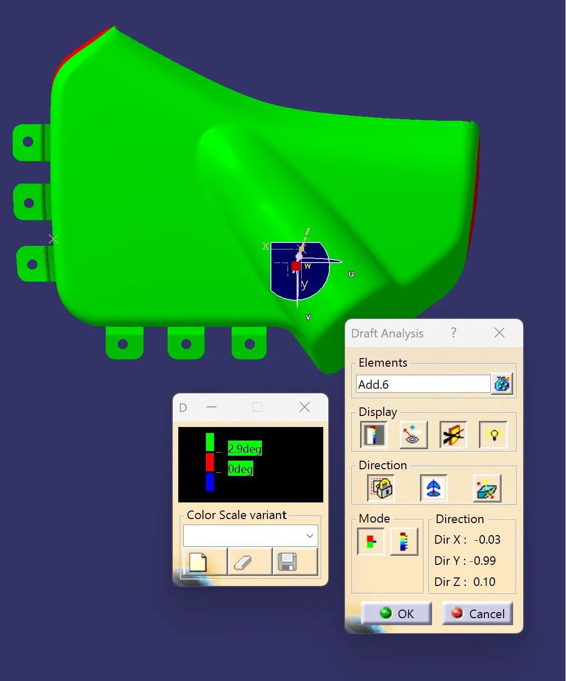
MAP POCKET:
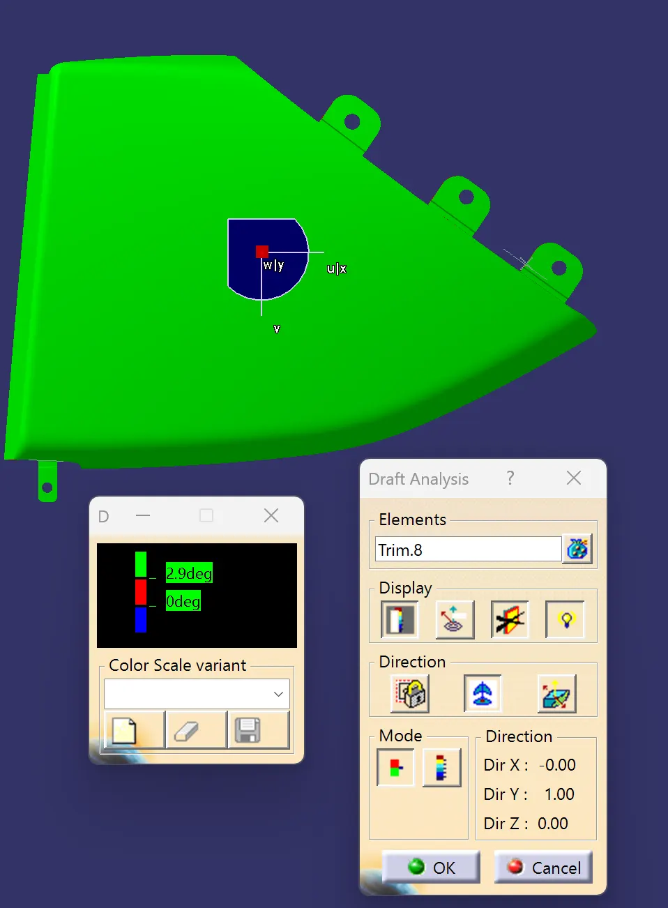
DOOR HARM REST:
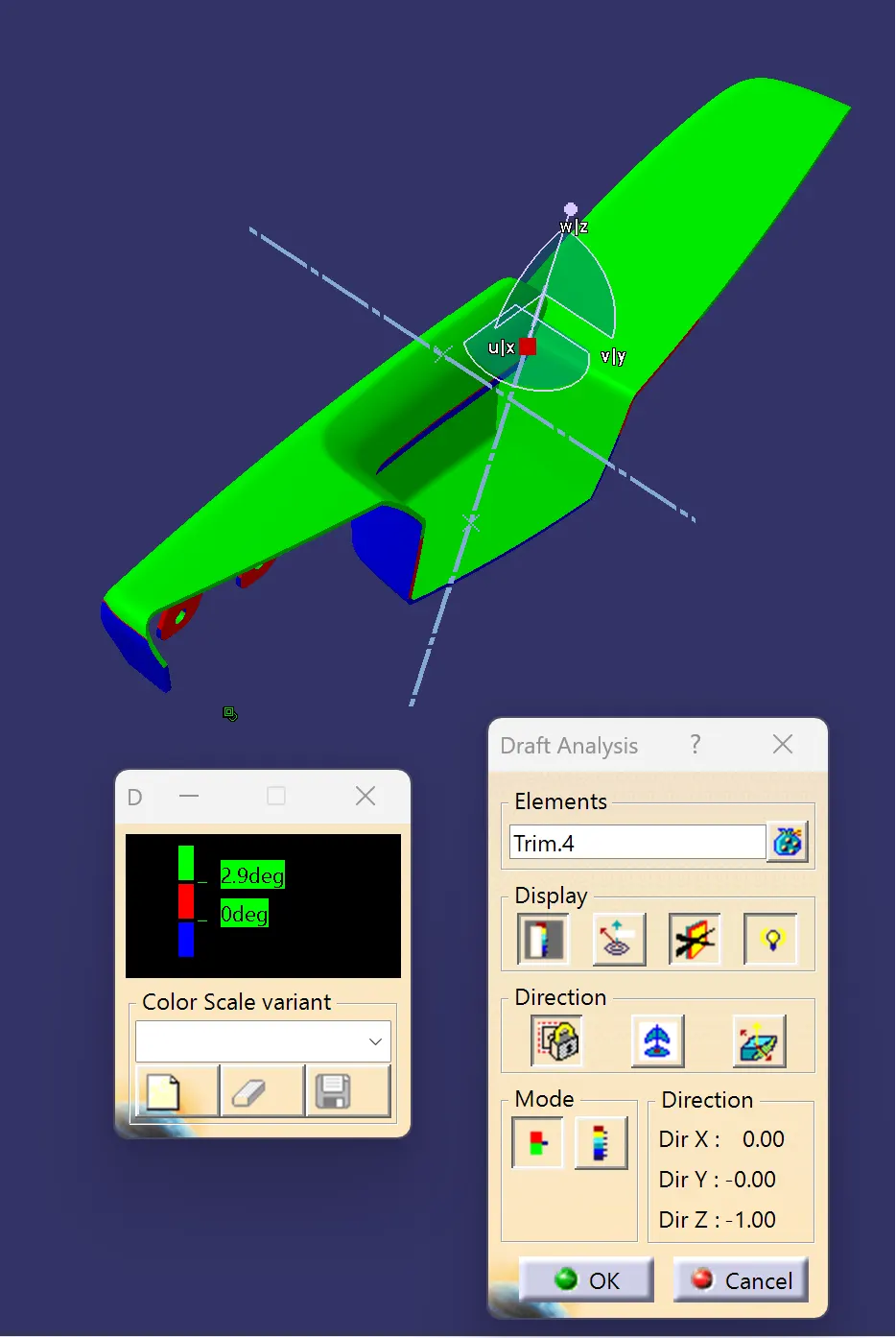
ALONG SIDE CORE AXIS :
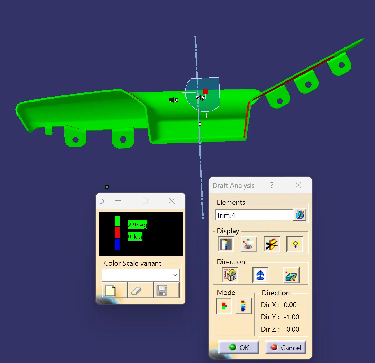
This negative draft is mainly due to the inclined curvature edges and the improper continution of the edges along the surfaces these are the changes that need to be updated and rectified by the class A surface input team .
Once all the solid bodies of the components are generated we need to move onto the B sifde attachment features.
The B side attachment features may include the
- Dog house
- Flanges
- Heat stakes & Ribs
- Locator
B side attachment features:
Once all the solid bodies are completed the assembly would be like
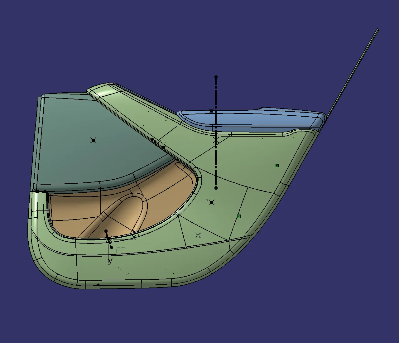
so for the final solid surface components we need to provide thye proper attachment features by adopting the industry design standards sand design parameters considerations.
AS a design engineer we need to have an idea regarding how a component need to connect wityh the adjacent component either by the flanges and the heat stakes assembly or with the flange and the locator assembly or with the dog house and the push pin etc
So we need to move step by step for creating the proper attachment features on each and every individual components of the door trim panel for the assembly of the component
Lower substract attachment features:
Based on the master sections provided for the for the input surface of the lower substrate it indicates theat the heat stakes are positioed on the surface
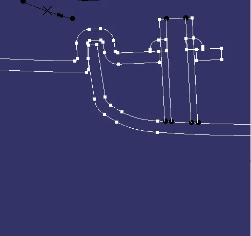
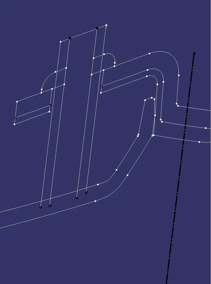
Following the master section wee need to create the heat stakes on the lower substract B side
Heat stakes :
Process for heat stakes assembly:
In thermal staking, also referred to as “heading or riveting”, the controlled flow of the molten plastic is used to capture or retain another component, usually of a different material.Thermal staking provides an alternative to welding when the two parts consist of dissimilar materials which cannot be welded or when simple mechanical retention of one part relative to another is adequate .
The most commonly used application involves the attachment of metal to plastic. A hole in the metal part receives a pre-molded plastic boss. The thermal tip contacts the boss and creates localized heat. As the boss melts, the light pressure from the horn forms a head to a shape determined by the horn tip configuration. When the heat is terminated, the plastic material solidifies and the dissimilar materials are fastened together.
So taking the references from the master section here we need to make a note of that whenever we take the reference from the master section the referenced elrement should be isolated from the master section
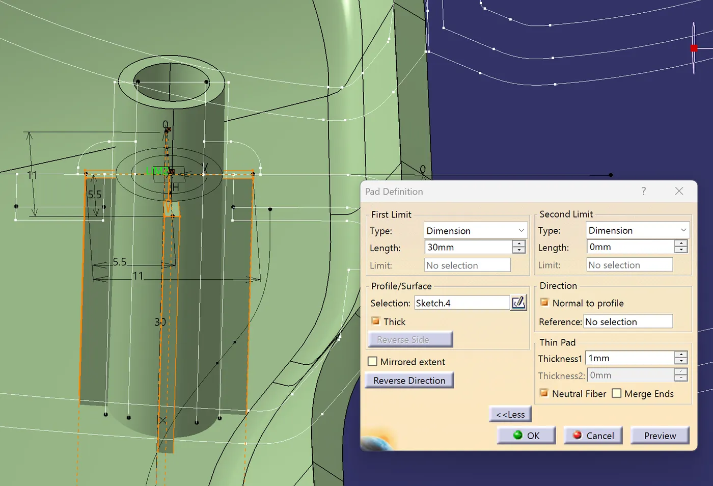
so start working on the heat stakes creation and provide the support it with ribs on the four sides to add additional strength to the heat stake
Design parameters:
- Height we need to follow the master section
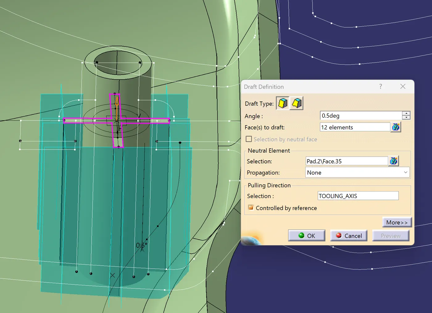
- Draft provided on the outer and the inner face with an angle of 0.5 degrees
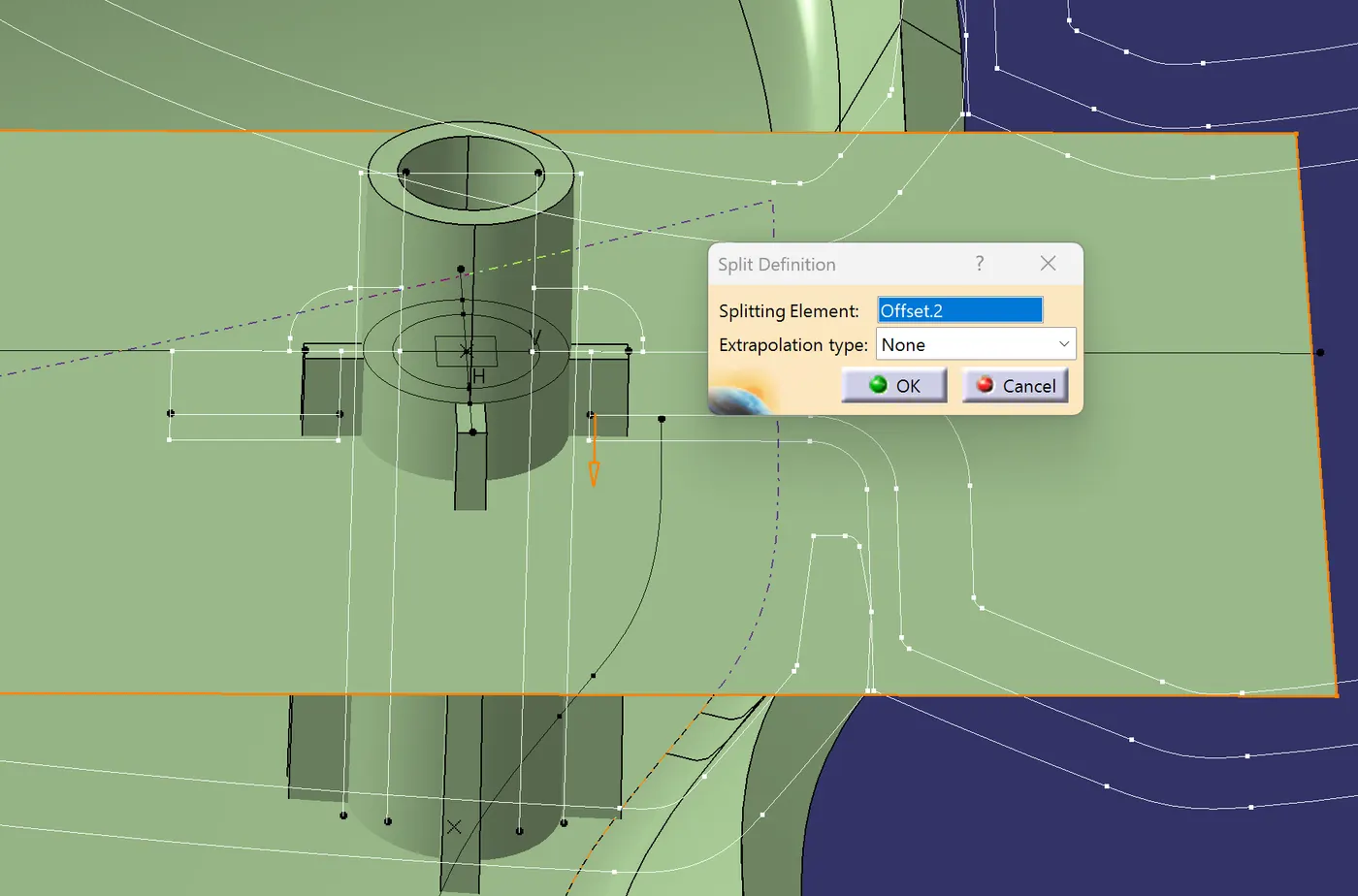
Create sketch the with refference to the master section
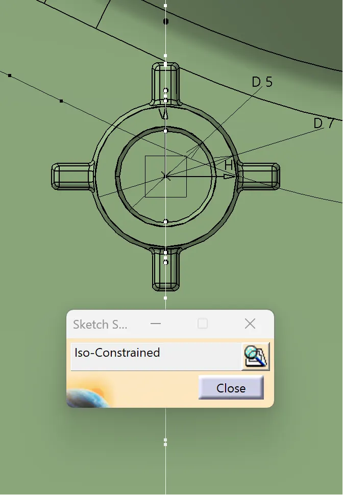
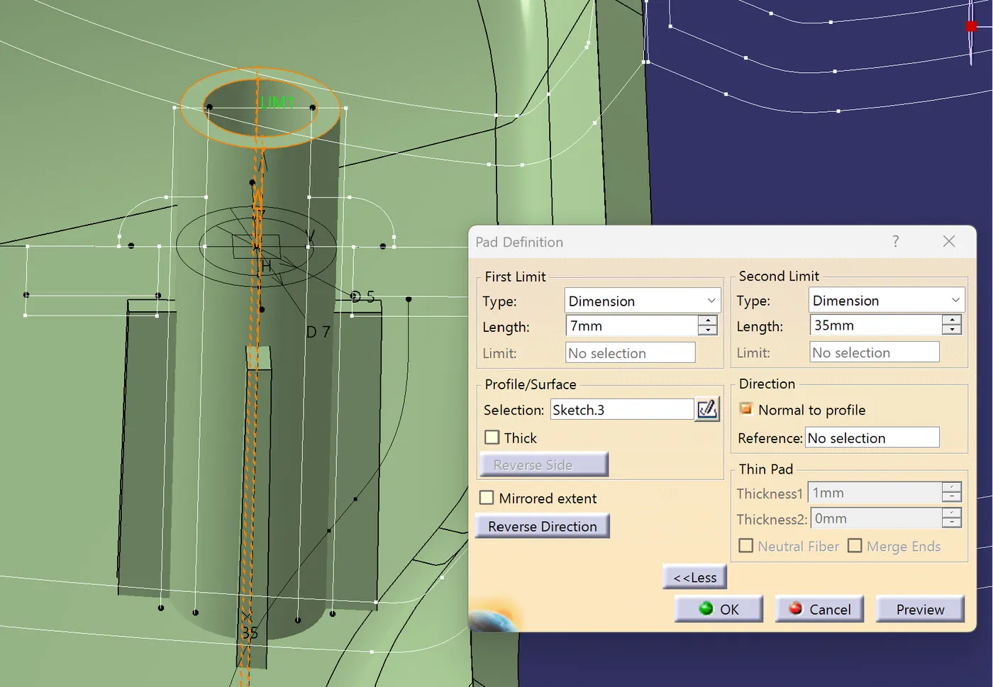
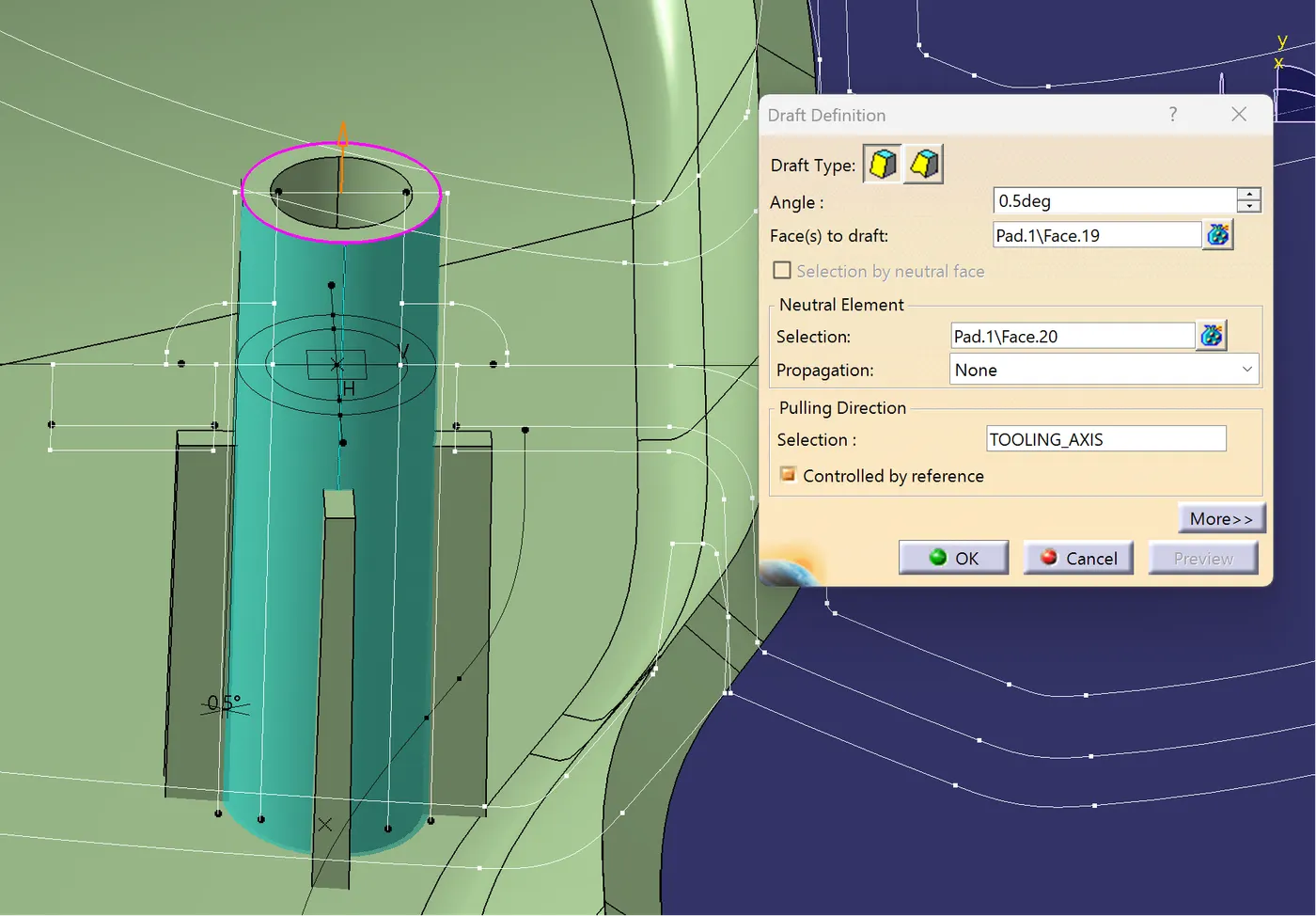
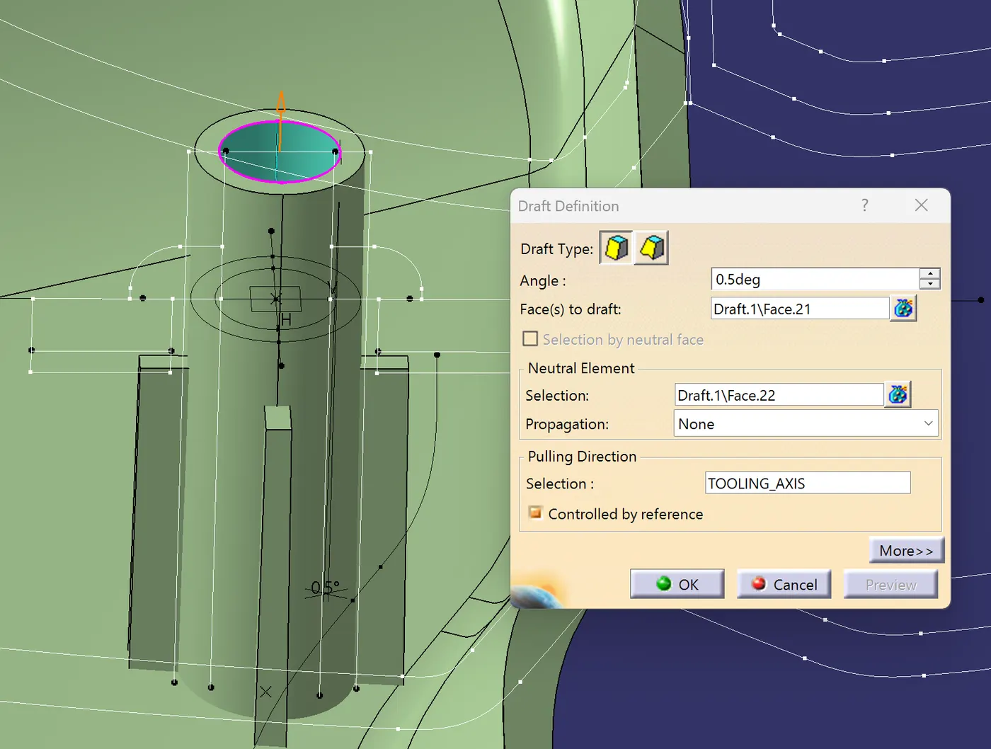
Create Ribs on outer of the heat stakes to privide additional support when we mounting mating part on it the flange should touches the Ribs.
Ribs provides a mean of strength and stiffness to the molded component without increasing the overall wall thickness
Ribs basically facilitates:
- Locating and arresting the components of an assembly
- Providing alignment in mating parts
- Acts as a guides or stops in mechanisms
Design parameters:
- Draft: 0.5 Degree per side (minimum) and maximum upto 1.5 degrees
- Thickness of ribs: 40 to 50% of wall thickness
- Height: ≤ 5 times the wall thickness
- Spacing (for more than 1 rib): 3:1- steel height/width ratio (maximum). h/w =3 or2(preferred) where h is the height of the rib and w is the space between two ribs.
- Minimum thickness at the tip: 0.75mm
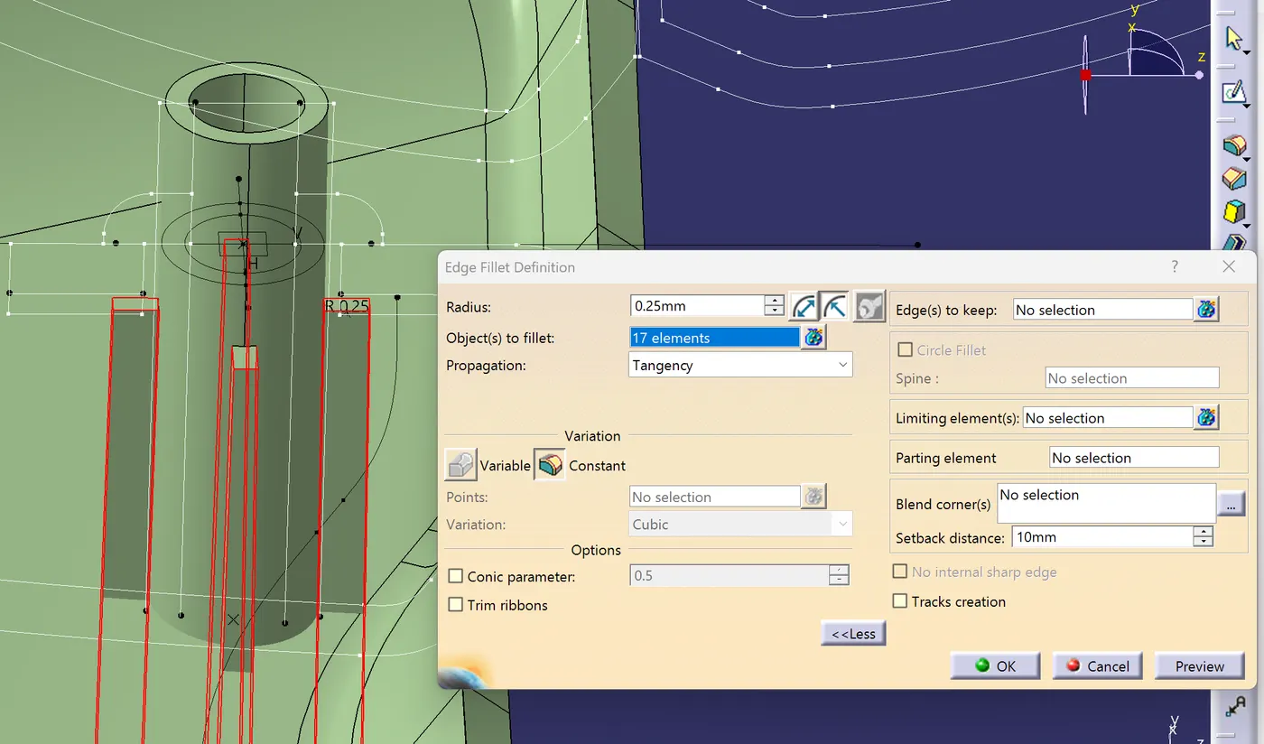
- Rib fillet Radius: 0.25mm max or 0.125*thickness of the component
- Rib root thickness should not be more than 30% of the wall thickness.
Start sketching the ribs as per ribs creation conditions.
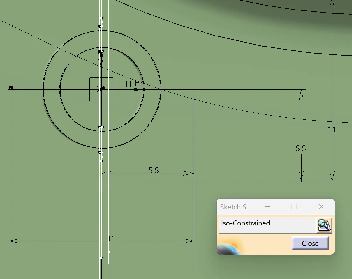
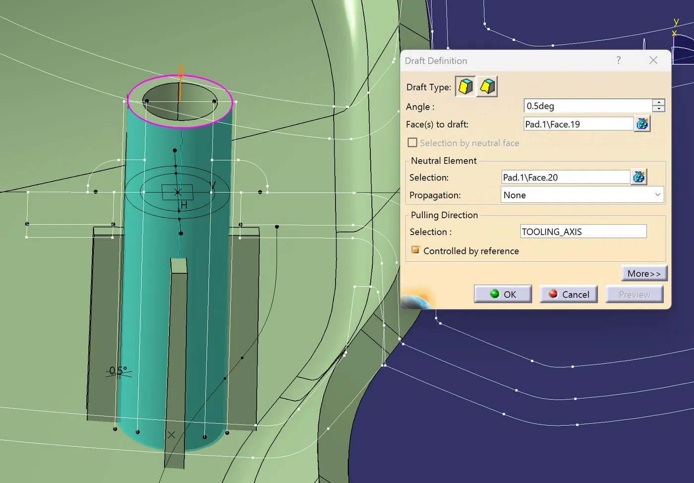
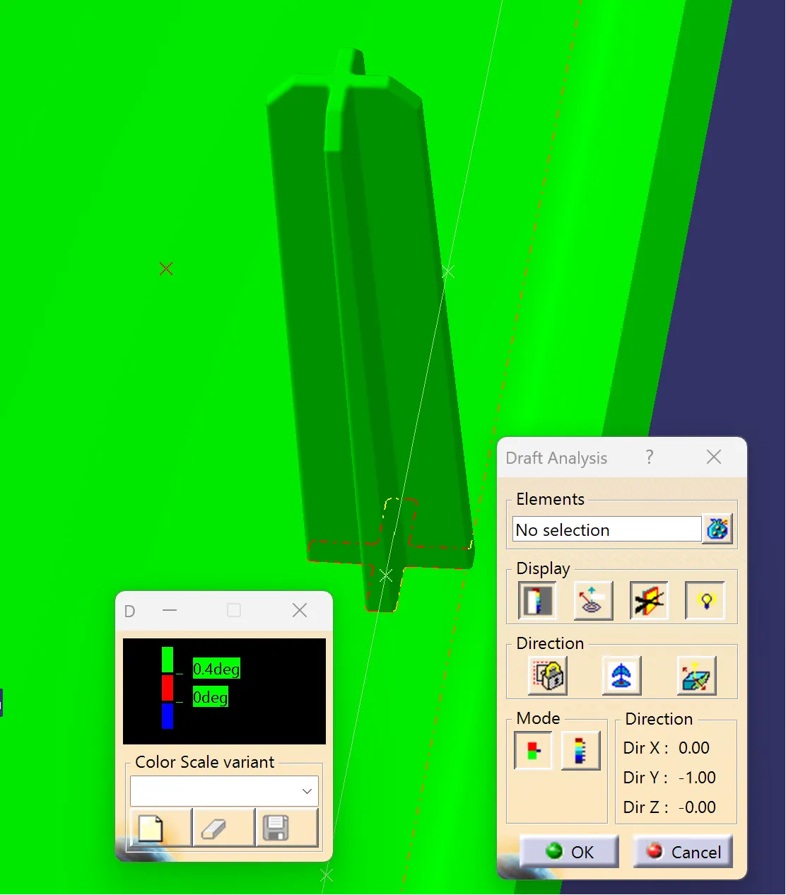
CHECK DRAFT ANALYSIS ALONG THE MAIN TOOL AXIS:
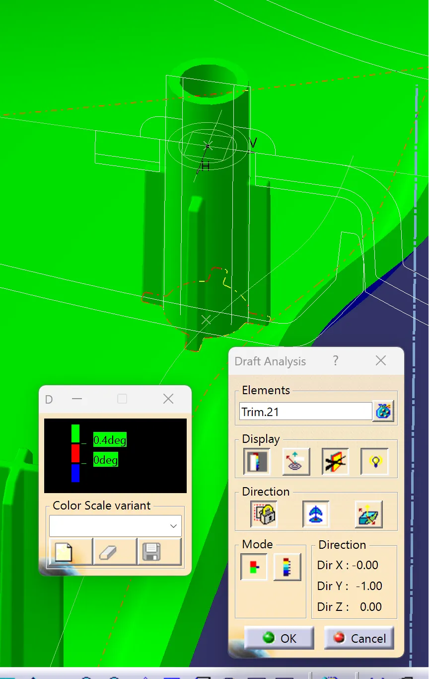
NOW WE NNED FOLLOW THE SAME STEPS TO CREATE REQUIRED NO OF HEAT STAKES.
LOCATOR:
- Locators are used to locating the position of the mating part while assembling,And to arrest the degere of freedom
- The design rule for the locator is mostly the same as the rib but the height of the locator should be more than the heat stakes at a min of 5mm.
- The locator also constrains the movement of the mating part.
- The gap between Flange and the locator should range between 0.5mm and 1 mm.
- There are two types of locators.
1. 2-Way Locator.
2. 4-Way Locator.
The design rules follows the same as in case of ribs foloowed by some changes the sketch.
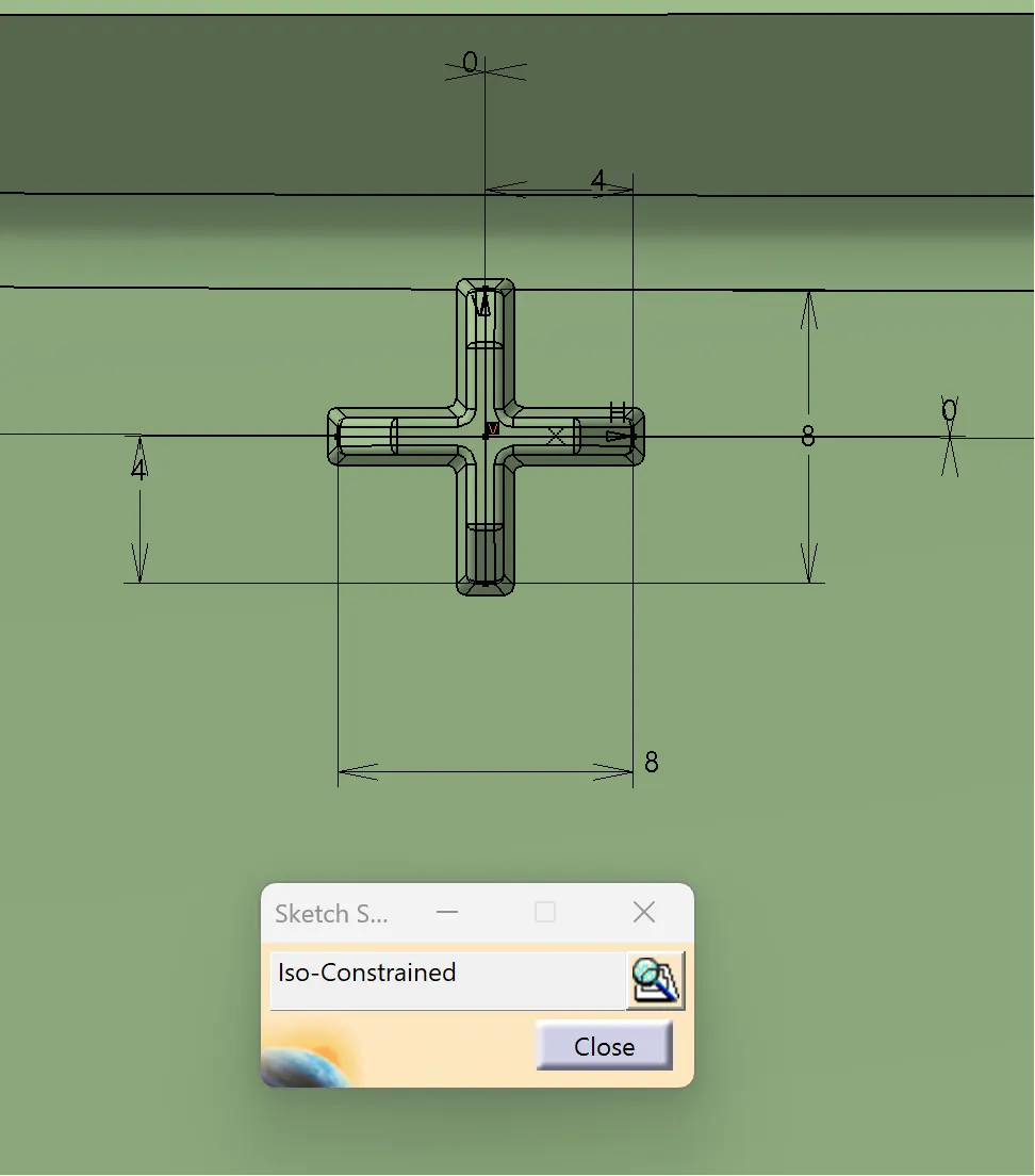
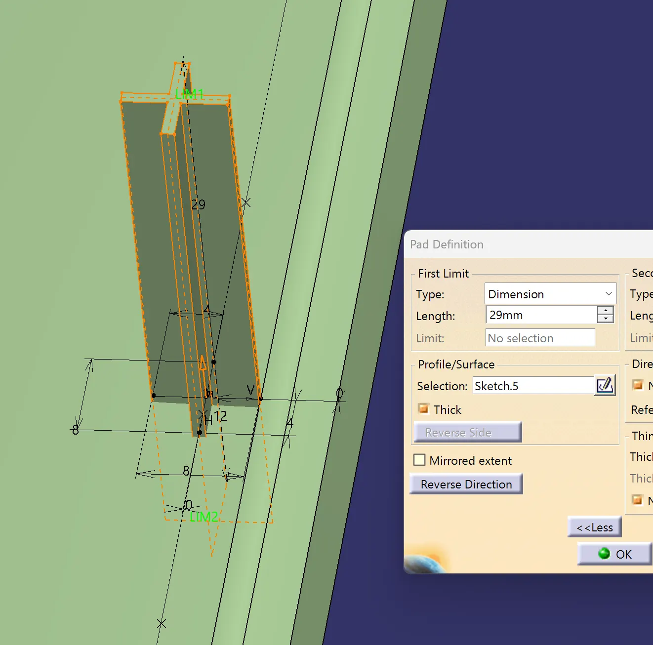
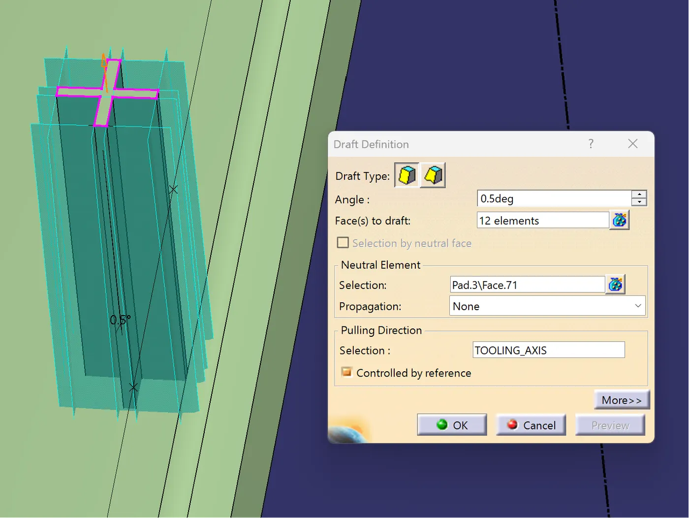
Dog house creation:
DOGHOUSE- Doghouse is an engineering feature used in the plastic trim design which helps to remove sink marks formed on Class-A surface while creating attachment feature on Class-B surface. Doghouse is a supporting feature, other features like locators, heat stakes, pushpins are mounted on top of doghouse for fixing and assembly purpose. Doghouses are subjected to draft analysis to prevent breakage of the component during ejection from the mould.
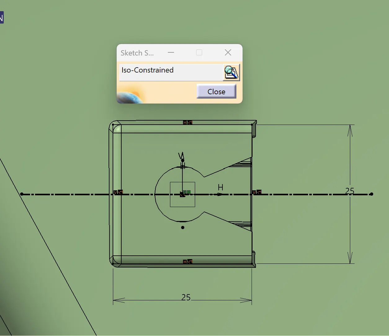
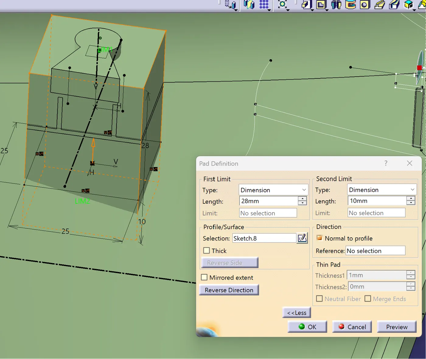
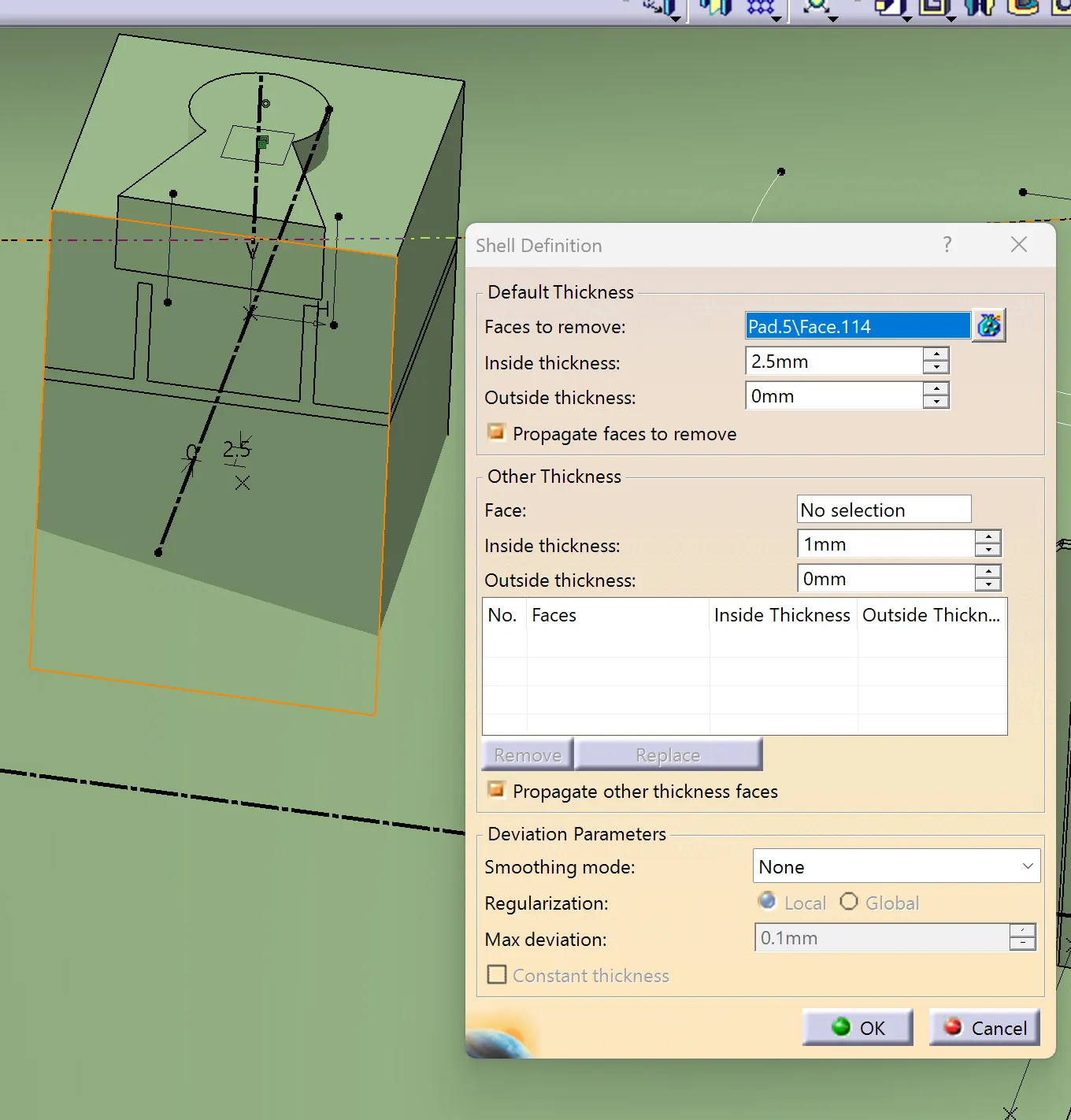
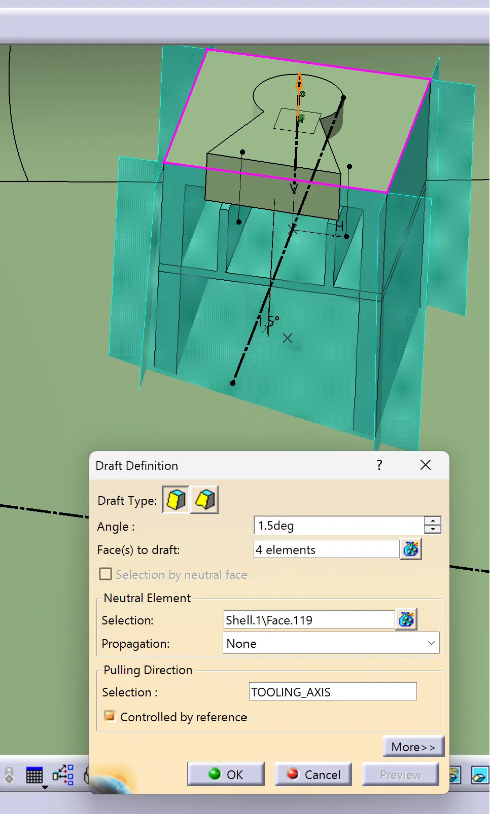
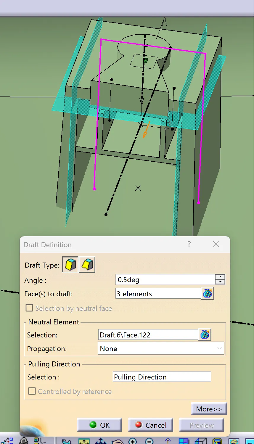
Here I has used a 25*25 dog house padded to a height of 40mm.
Create the sketch
CORNER RADII
Properly designed corners will make a big difference to the quality, strength and dimensional accuracy of a moulding. But there is another benefit too. Smooth curved corners help plastic flow in the mould by reducing pressure drops in the cavity and minimising flow-front break-up. Internal radii should be at least 0.5 and preferably 0.6 to 0.75 times the wall thickness.
CORNER RADII=(0.6-0.7 mm)
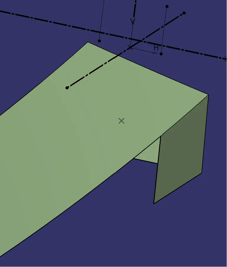
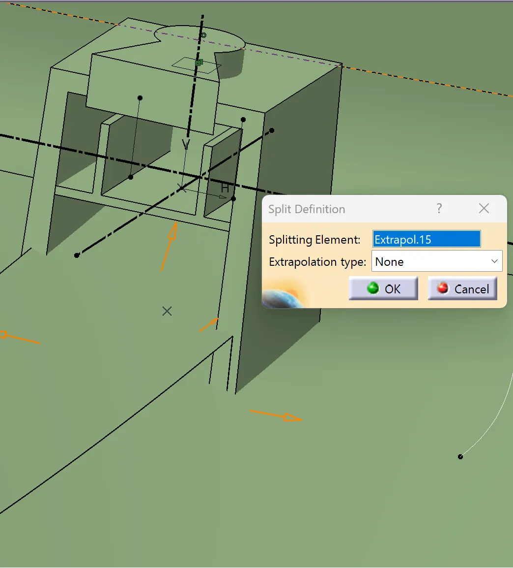
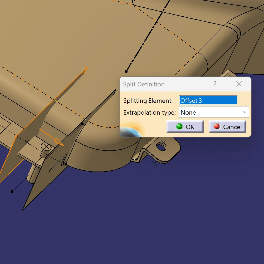
use split command spit from dog house main body,
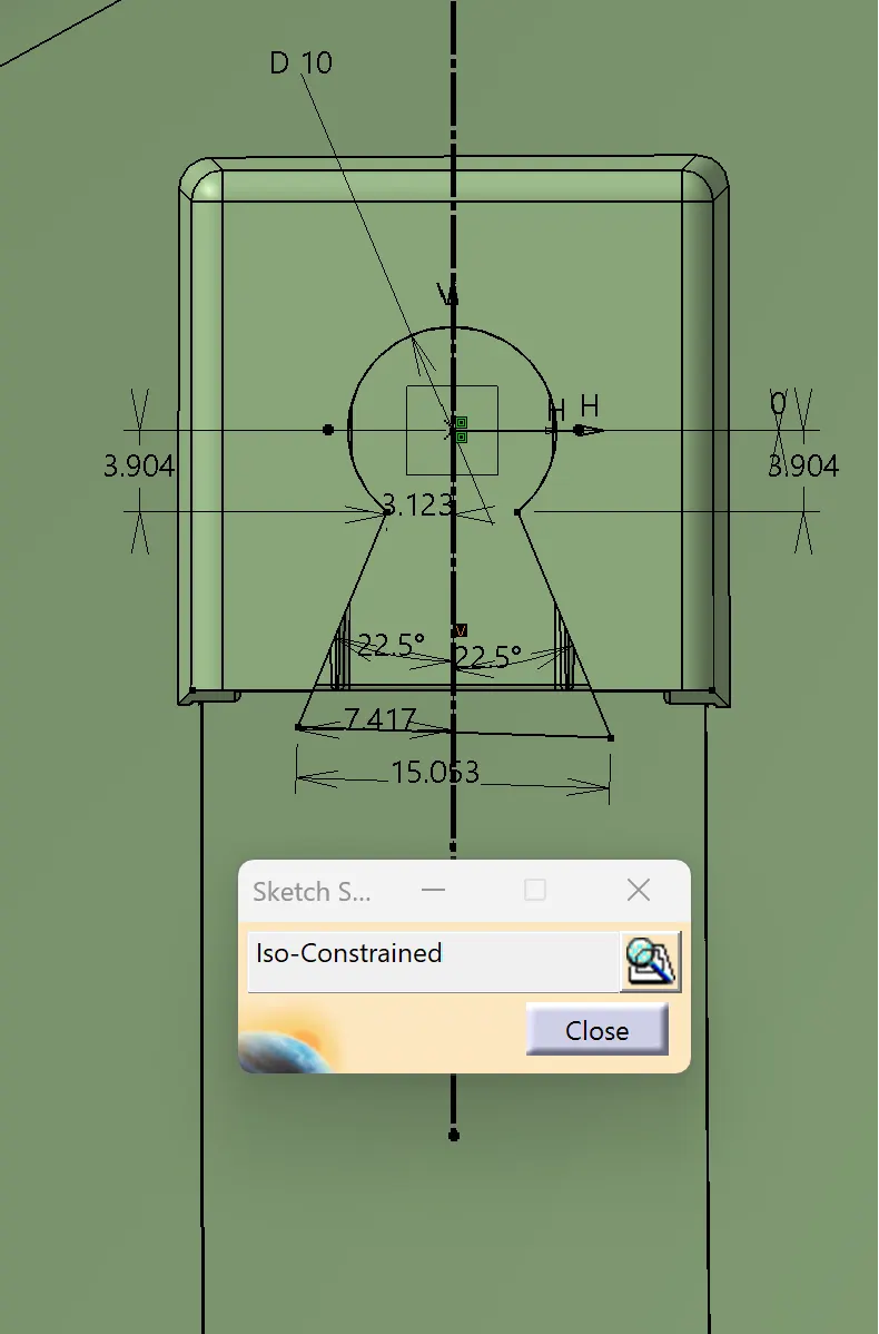
CREATION OF CUT OUT CLEARENCED OF POSINING THE PUSH PIN MECHANISEM.
CREATE THE SKETCH.
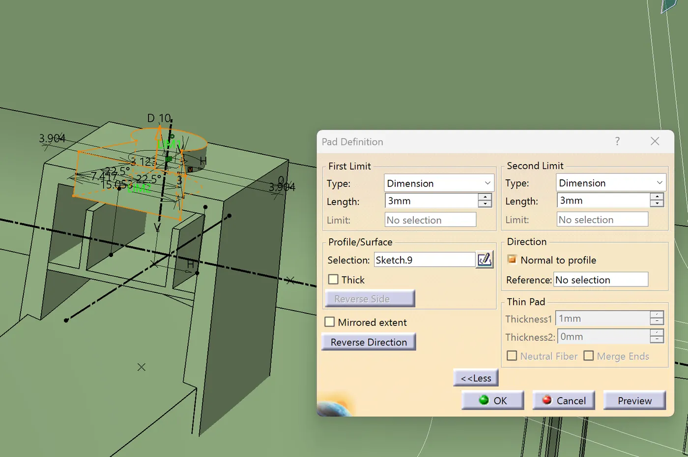
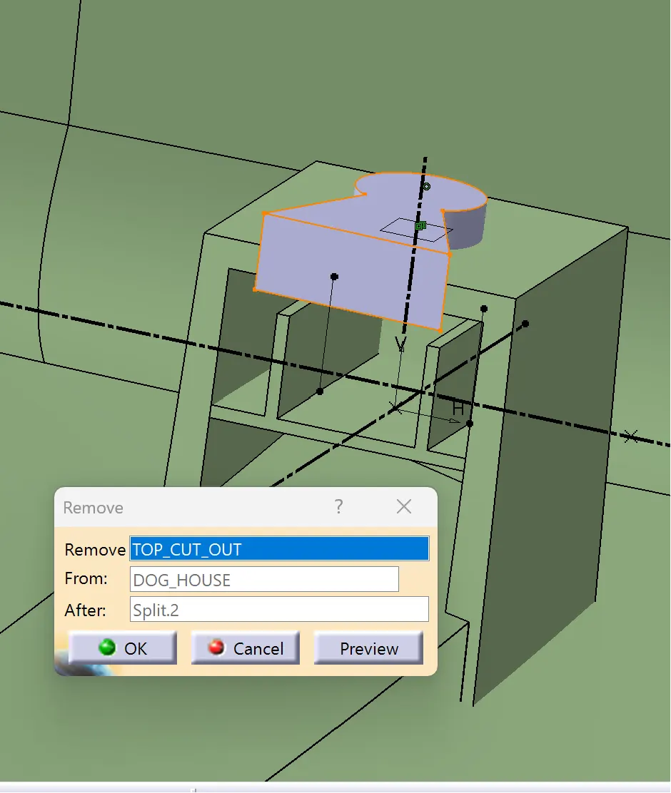
USE THE BOOLIEAN COMMANDS,
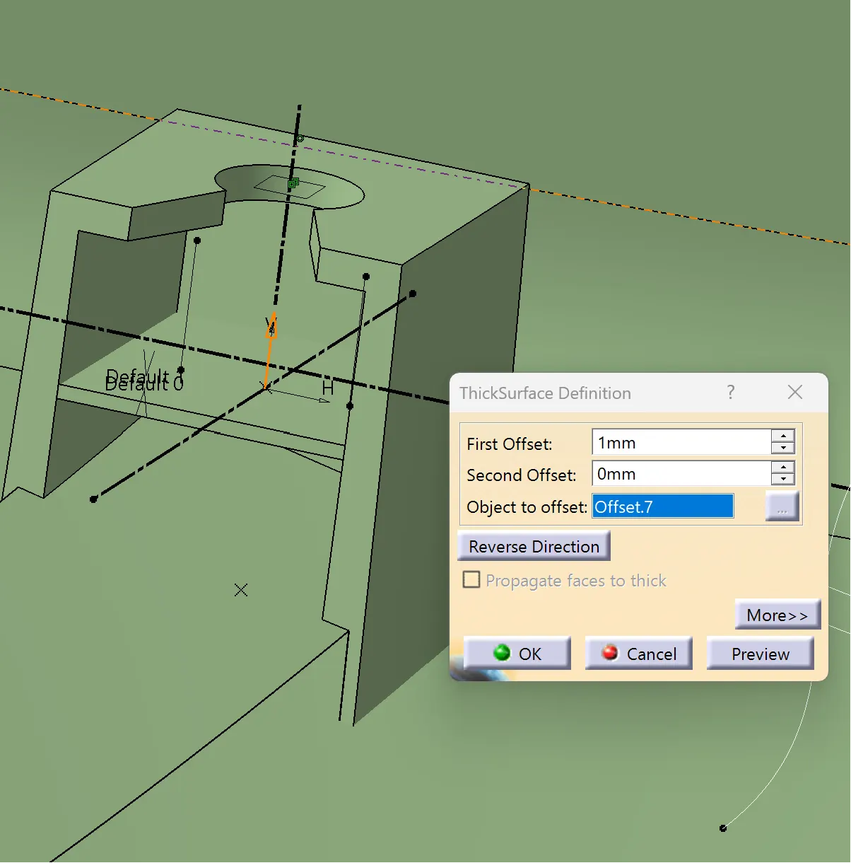
Rib cage:
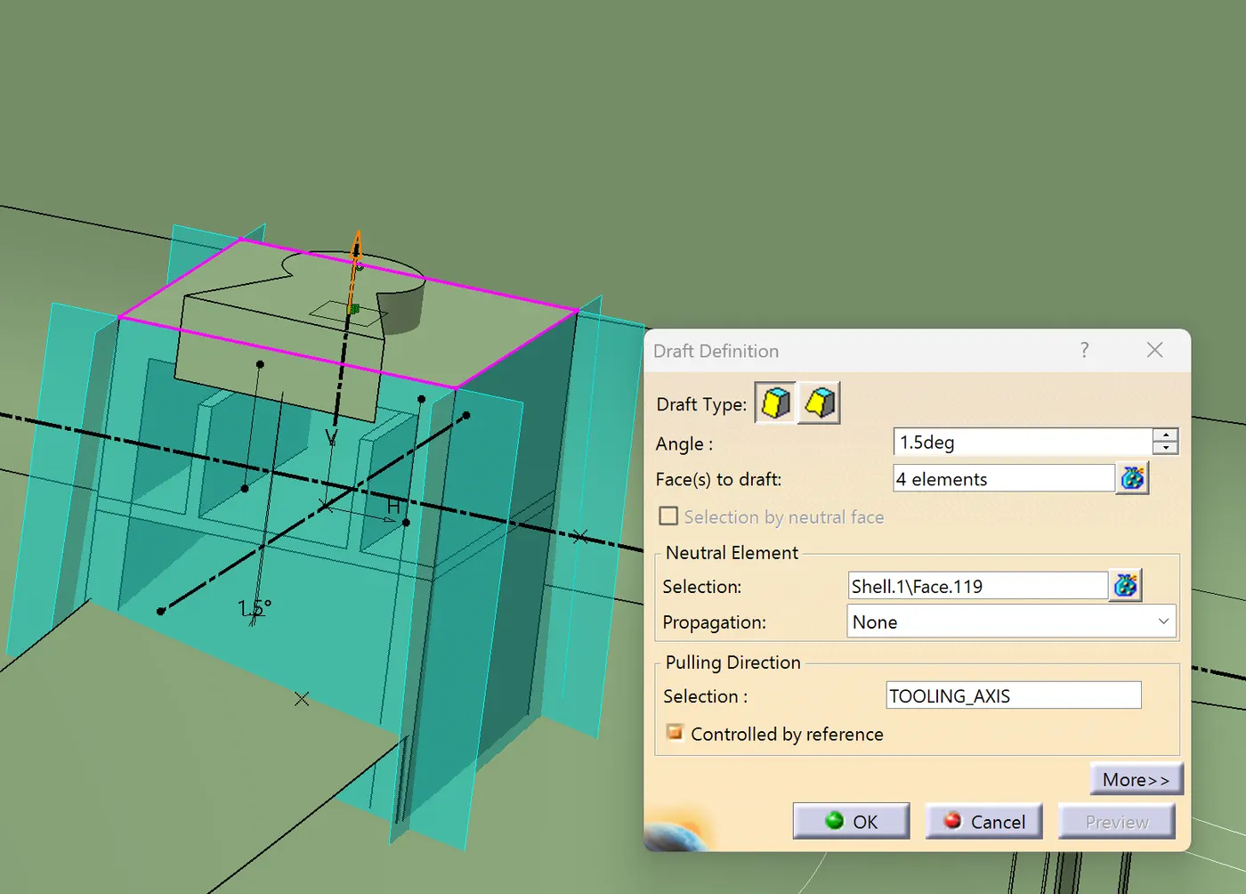
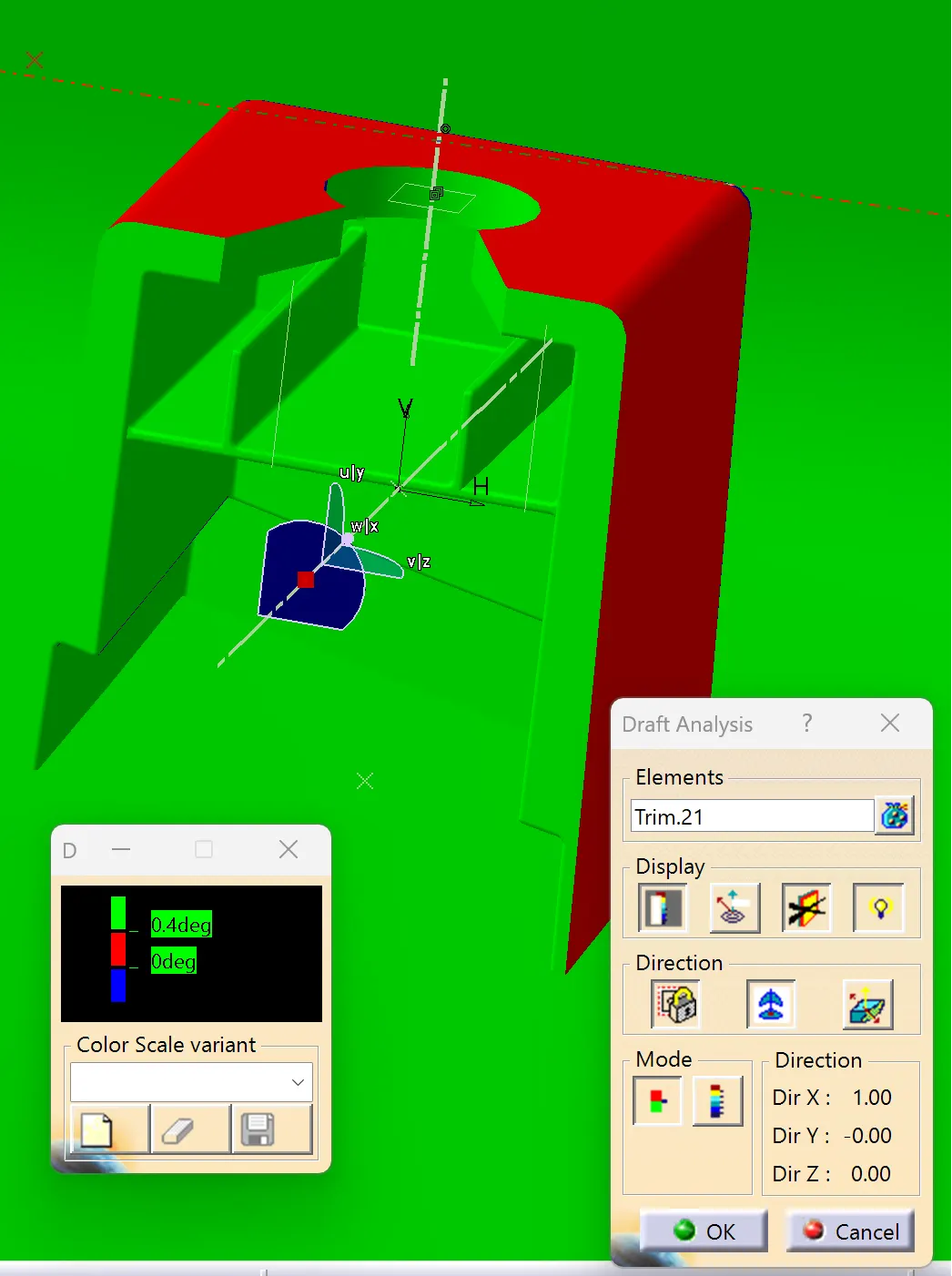
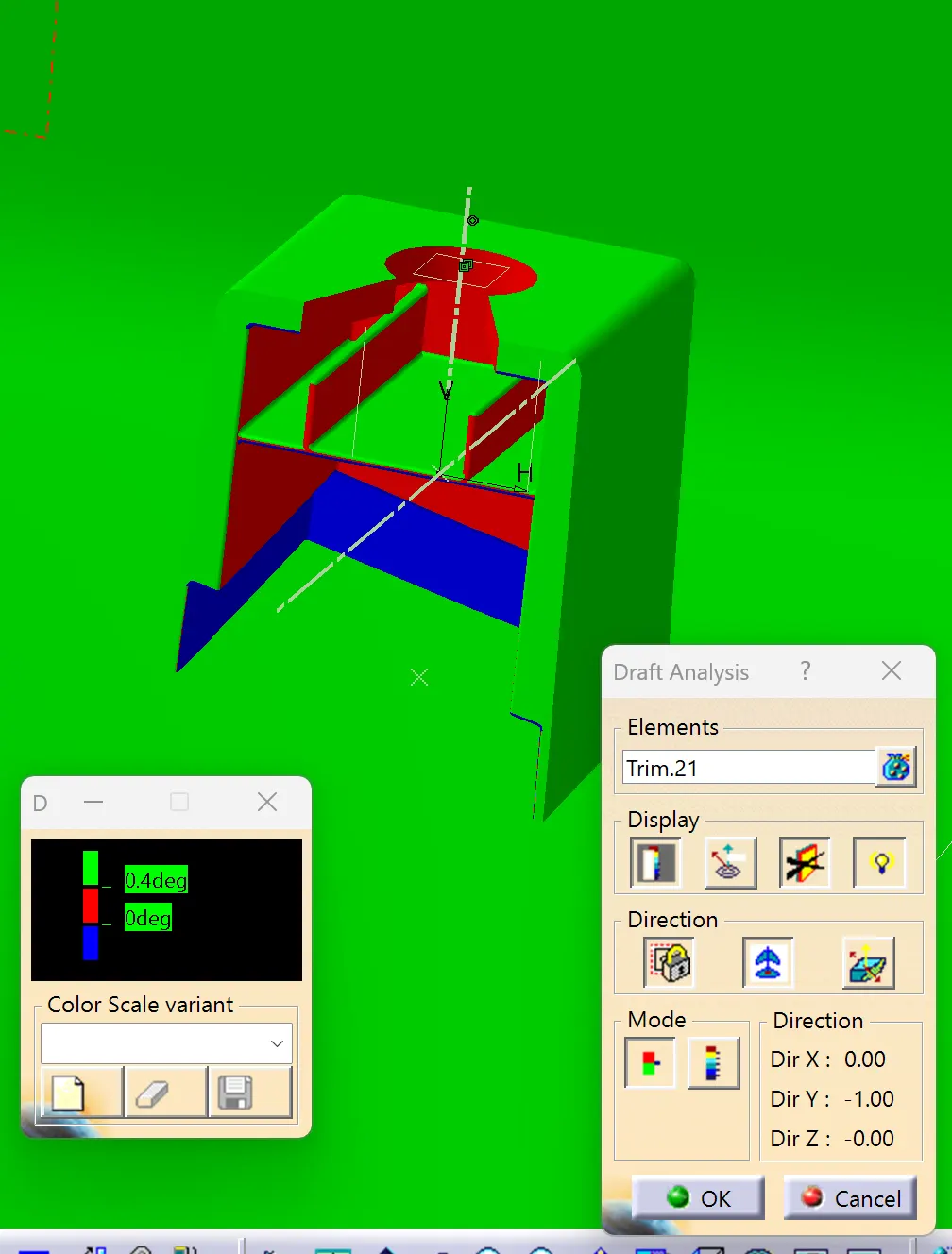
For provoding the additional support for the dog house we create a rib cage with two ribs of 1 mm thickness and providing a draft of 0.5 deg with respect to the side core tpooling axisb
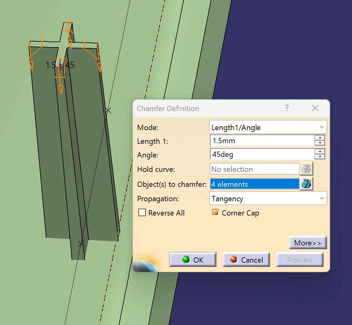
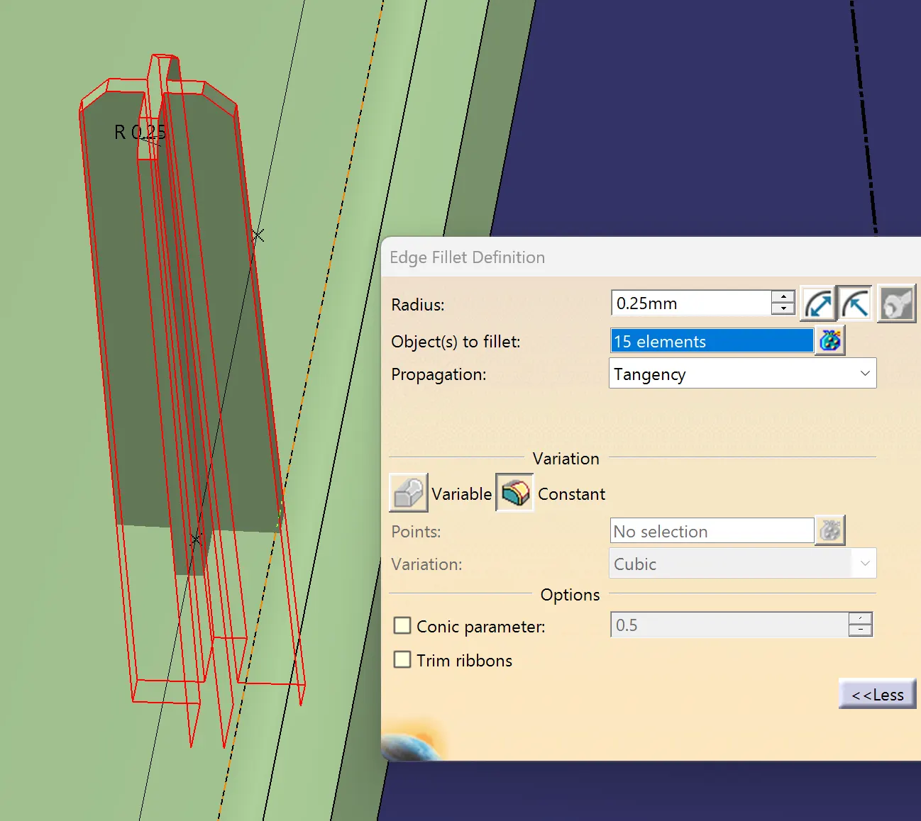
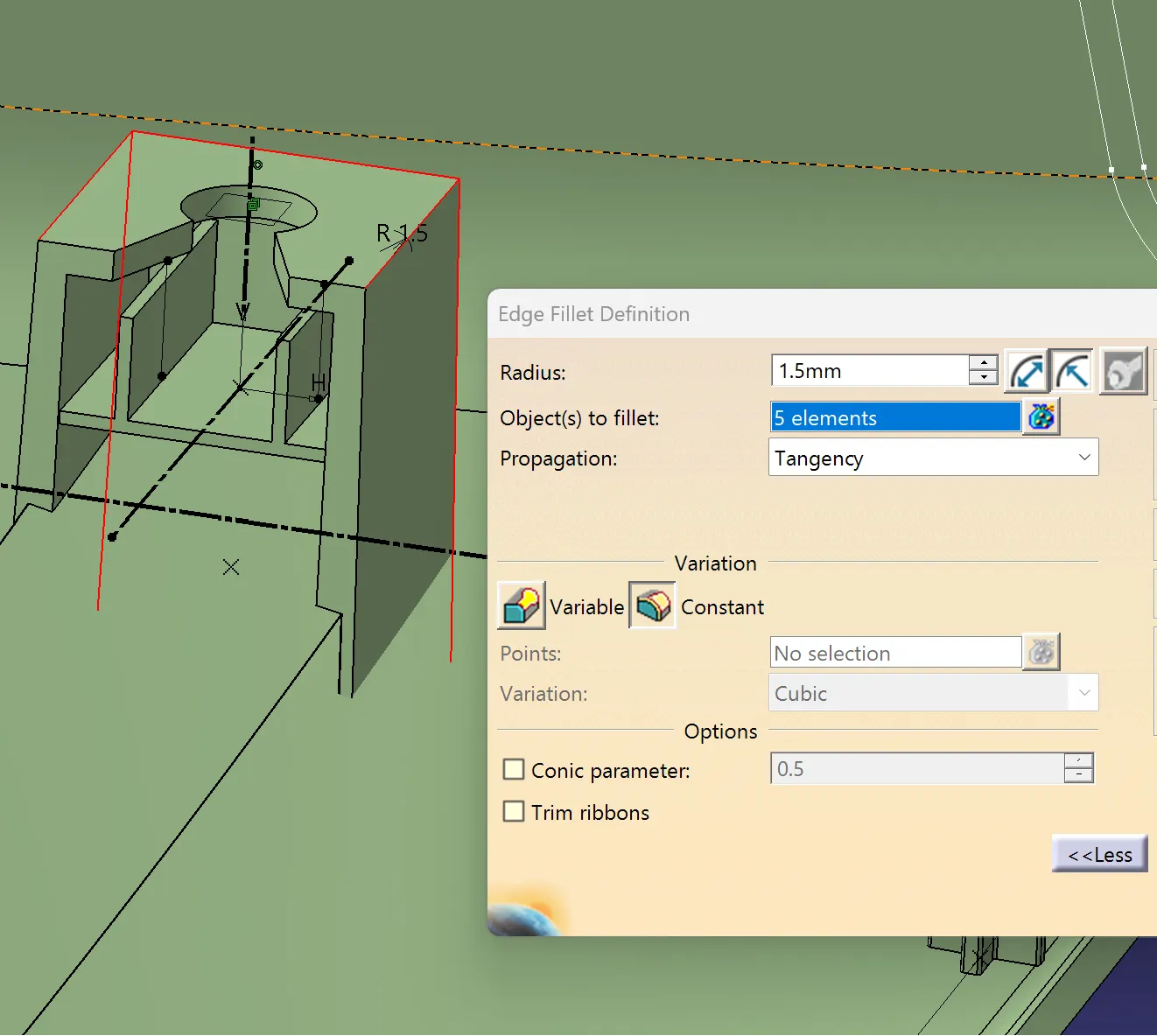
PROVIDE THE MINIMUM EDGE FILLET OF 1.5 ON OUTSIDE AND PROVIDE O.25
ALONG SIDE CORE AXIS:
ALONG THE MAIN TOOLING AXIS:
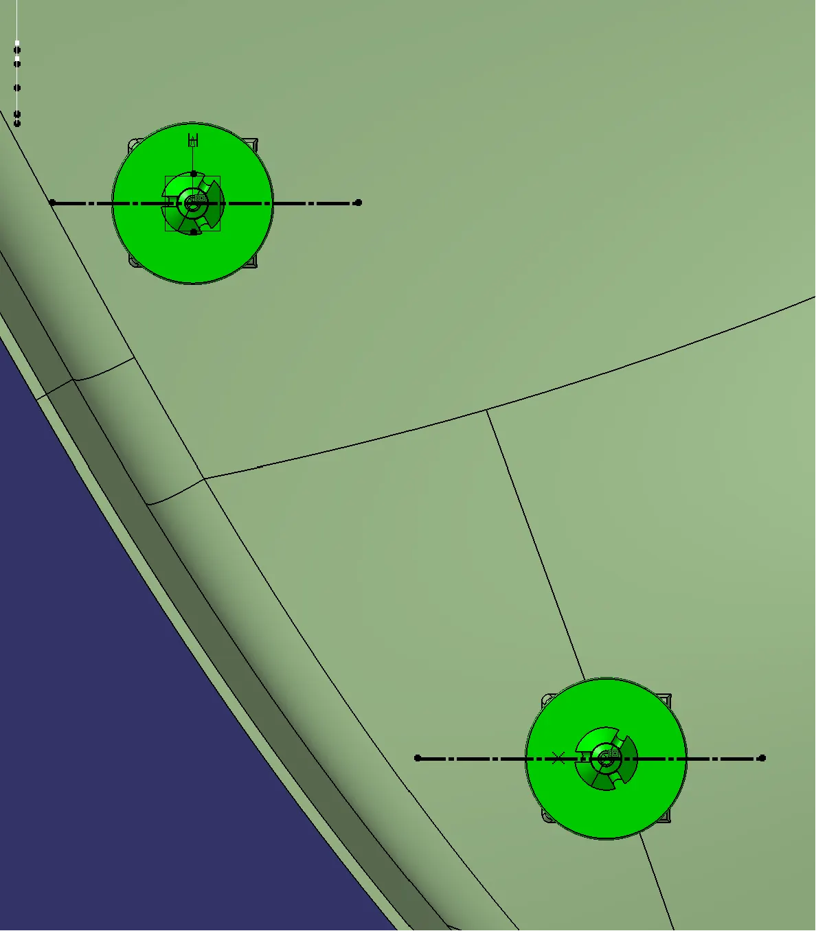
SO on the lower substract we need to provide upto 2 dog house maintaining that there might not be any engineeering feature with in a direction of the slider movement upto 90mm (minimum distance )
We use the translate option from point to point translation to copy and paste the dog houses atb arious locations and use the rotate option to change the direction of the opening for the slider
These are the 2 dog housess along with their slider axis
B side attachments on the Door arm rest:
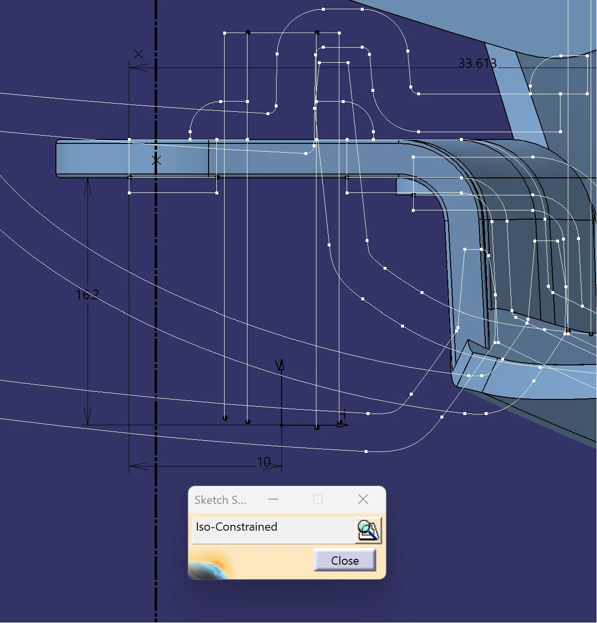
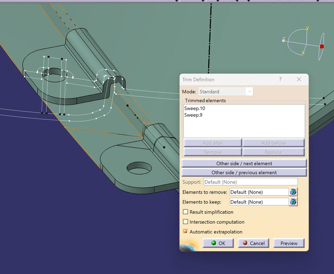
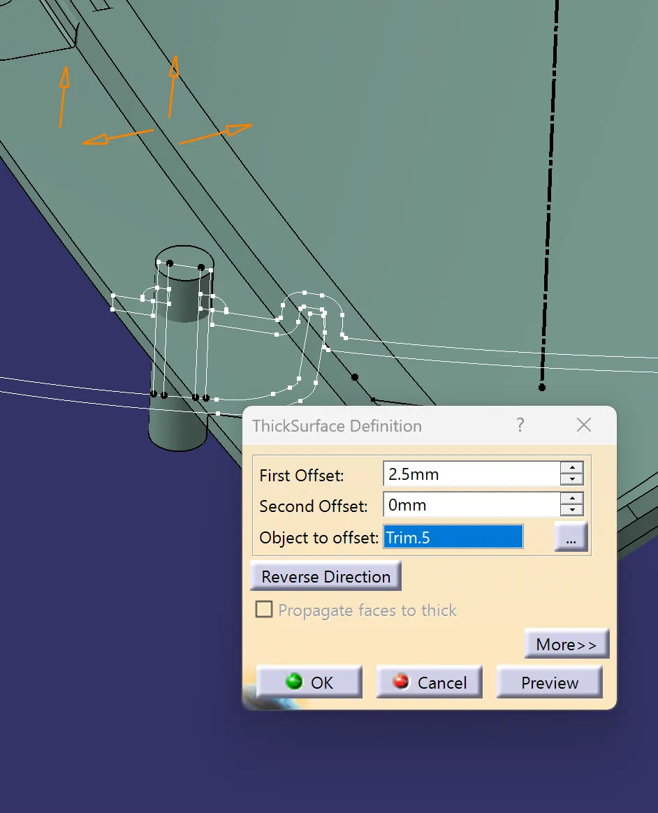
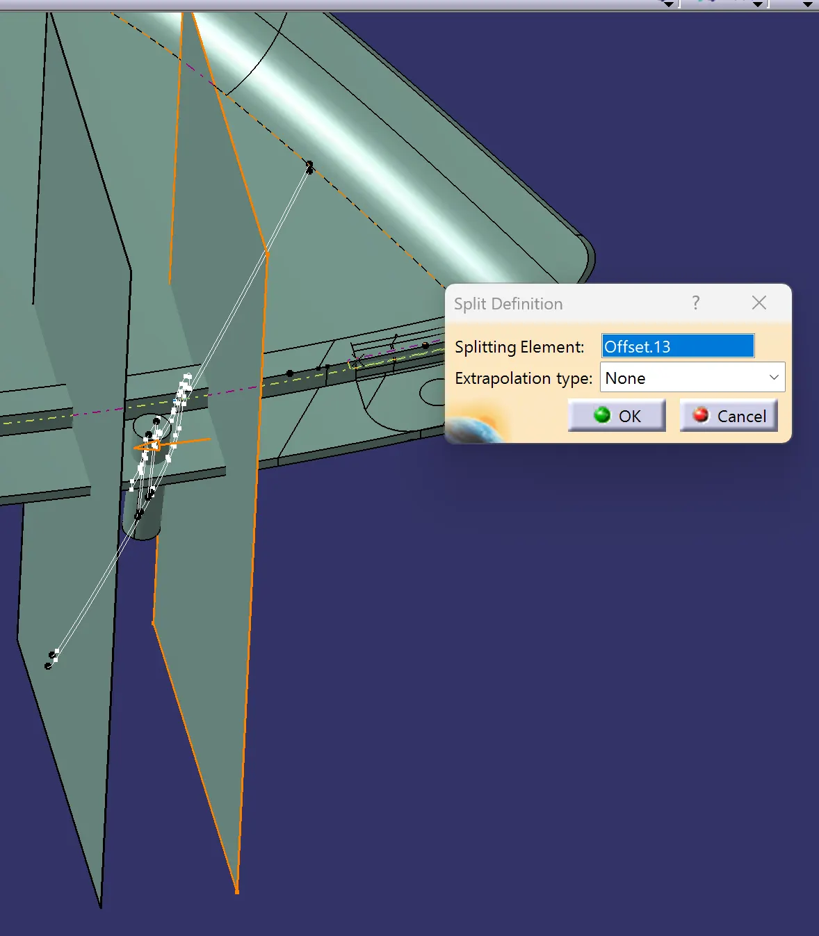
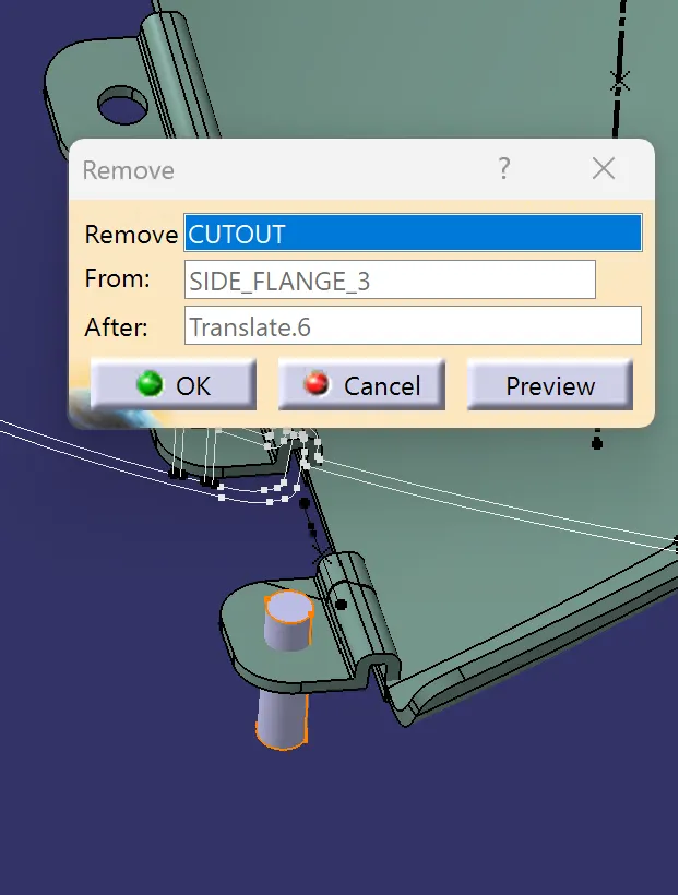
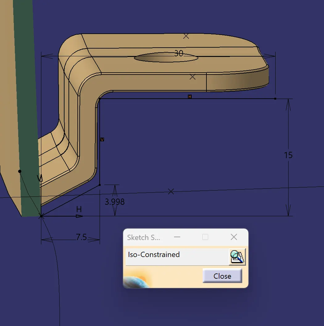
Flanges are the joining features that help to assemble different components. The mastersection was used to make flanges. After creating one flange point to point translation is used to translate the flanges. We need to provide a draft of 0.5 degrees for the flanges . The gap between flanges should be 50-100 mm. Boolean operations were used to add attachment features into closed body
Design:
In case of te door arm rest we need to folow the master section provided for the flange creation
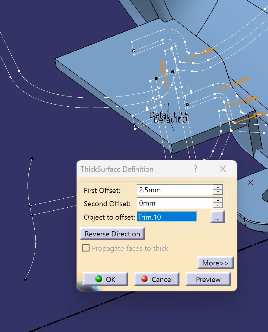
The thickness of the flange is equal to the thickness of the plastic component that is 2.5 mm
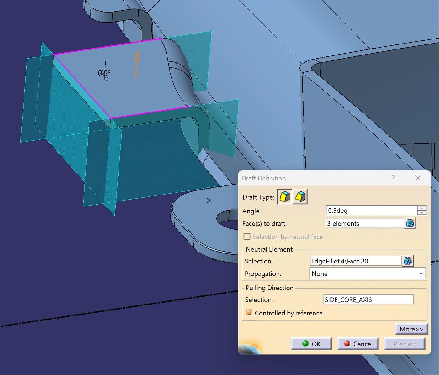
The draft provided is 0.5 deg
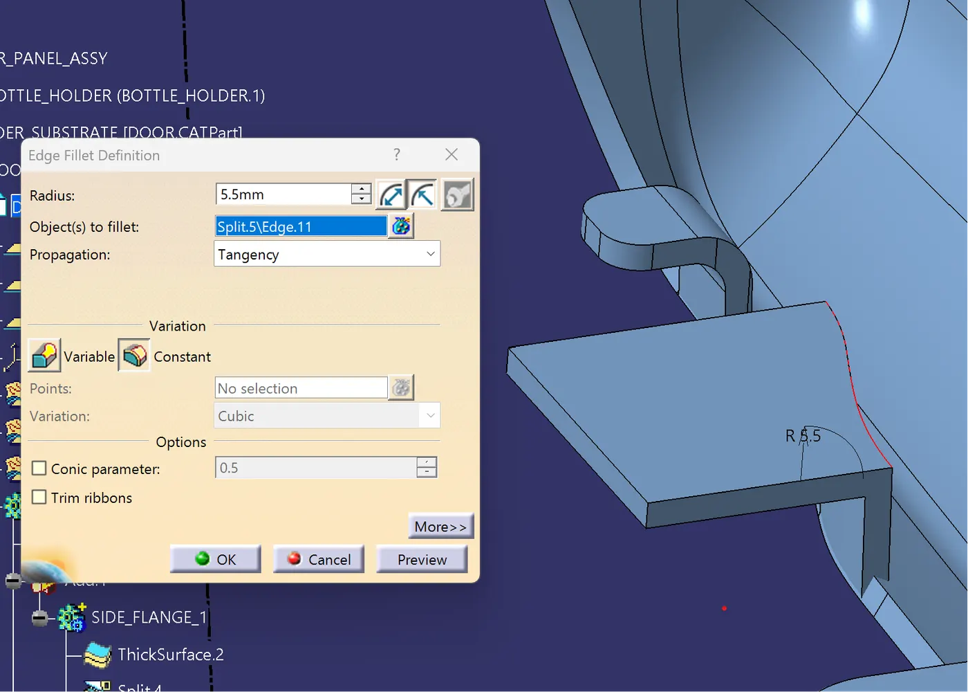
Apply requierd fillets on all the sharp edges
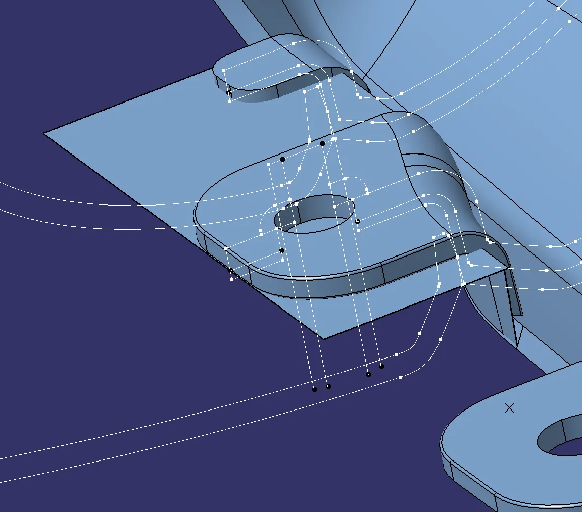
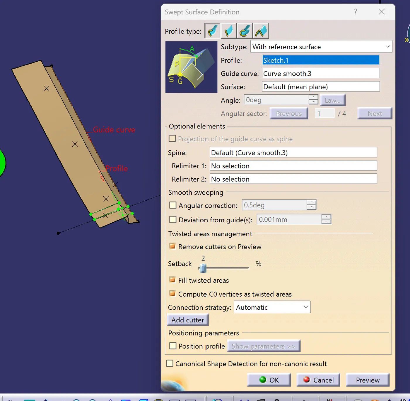
The sketches taking the references from the master section are
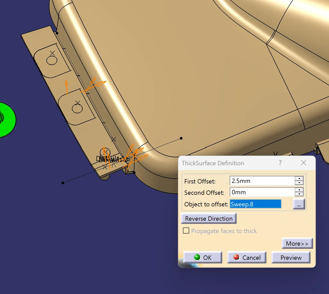
BY USING SWEEP THE COMMAND AND THICKEN IT AS PER MASTER SECTION
Thiocken the surface in the part workbench with a thickness of 2.5mm
Apply a draft of 0.5 deg on the edges of the flange
Now apply then proper fillets on the corner edges
Now make a hole on the hole to position then heat stake or the locator with respect to the flange for proper assembly
The diameter of the hole should provide of claerance of 0.5 to 1 mm between the flange and the heat stake or with the flange and the locator
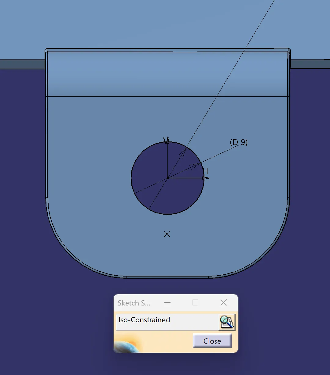
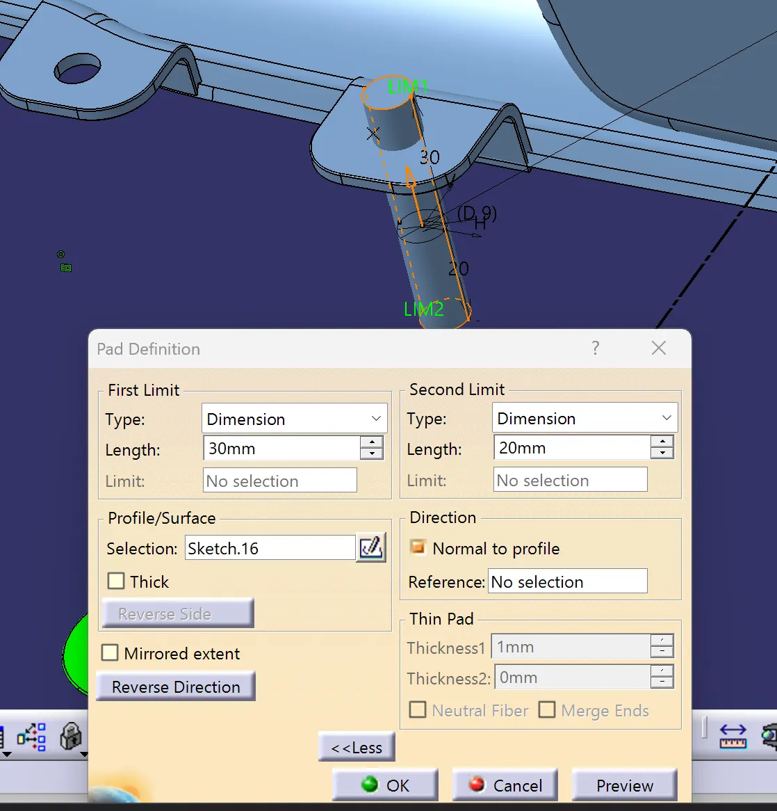
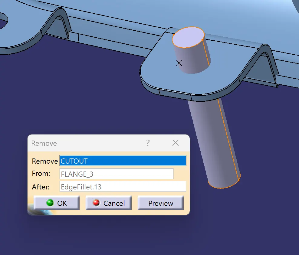
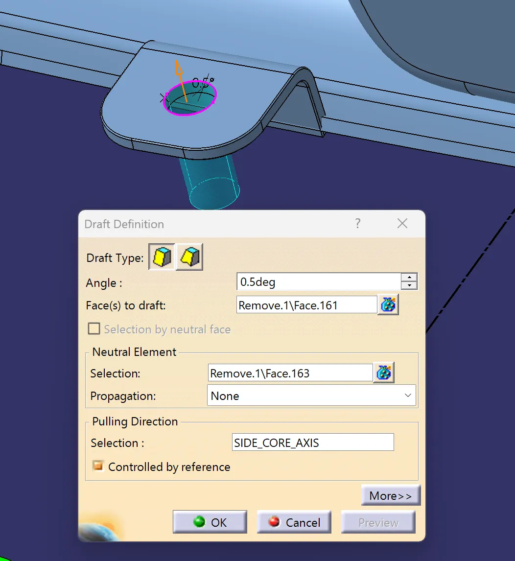
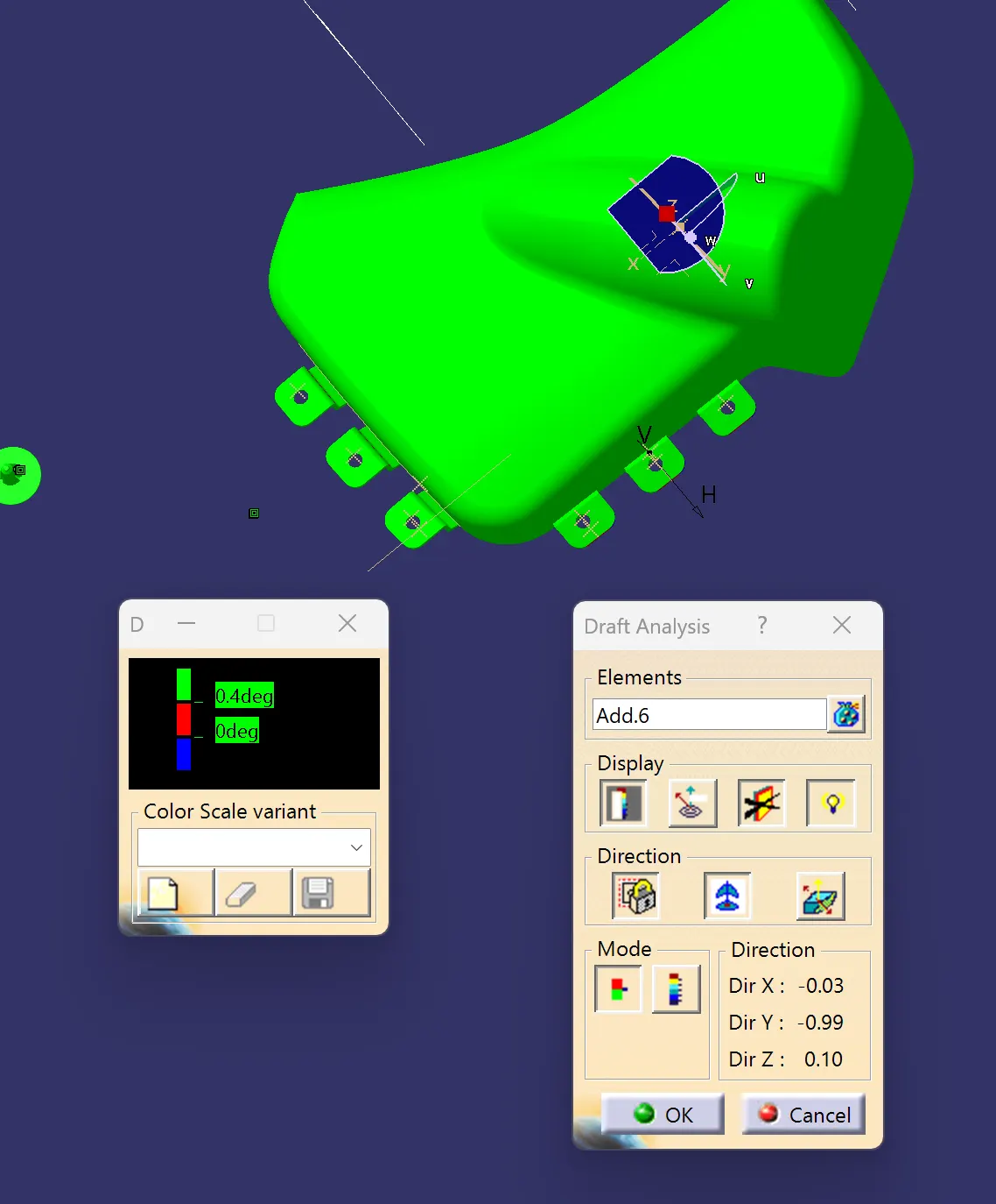
Draft analysis flanges with minimum draft of 0,5 mm along side core tooling axis
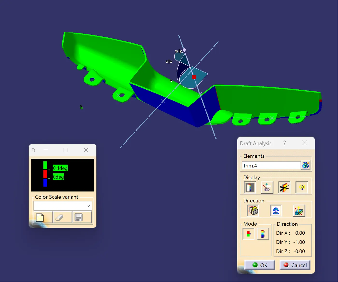
IN ACCORDINGLY WE NEED FOLLOW THE SAME STEPS FOR FOR CREATING THE FLANGES OF MAPM POCKET & BOTTLE HOLDER.
MAP POCKET:
CREATE THE SKETCH WITH REFFERENCE TO THE MASTER SECTION.
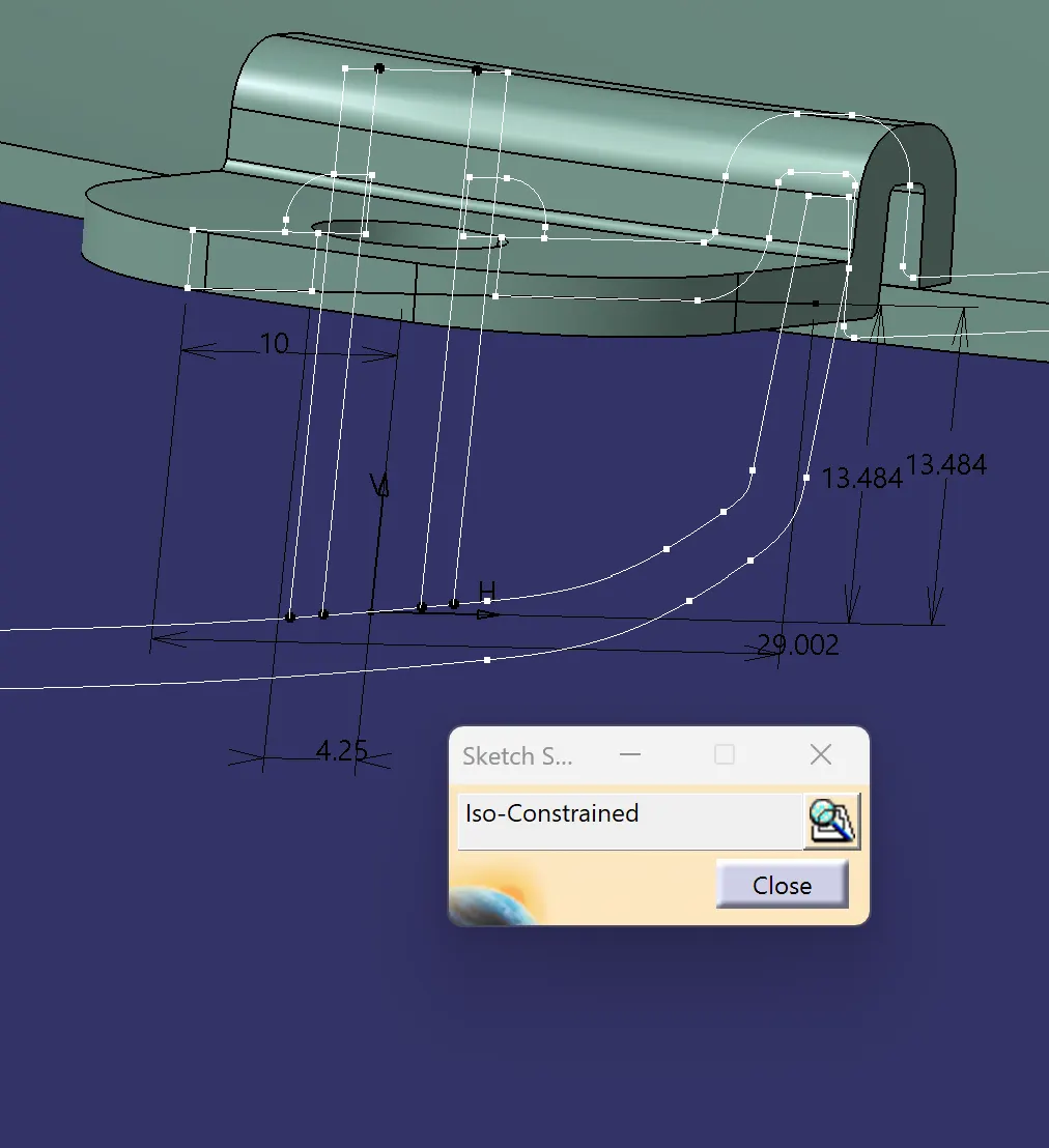
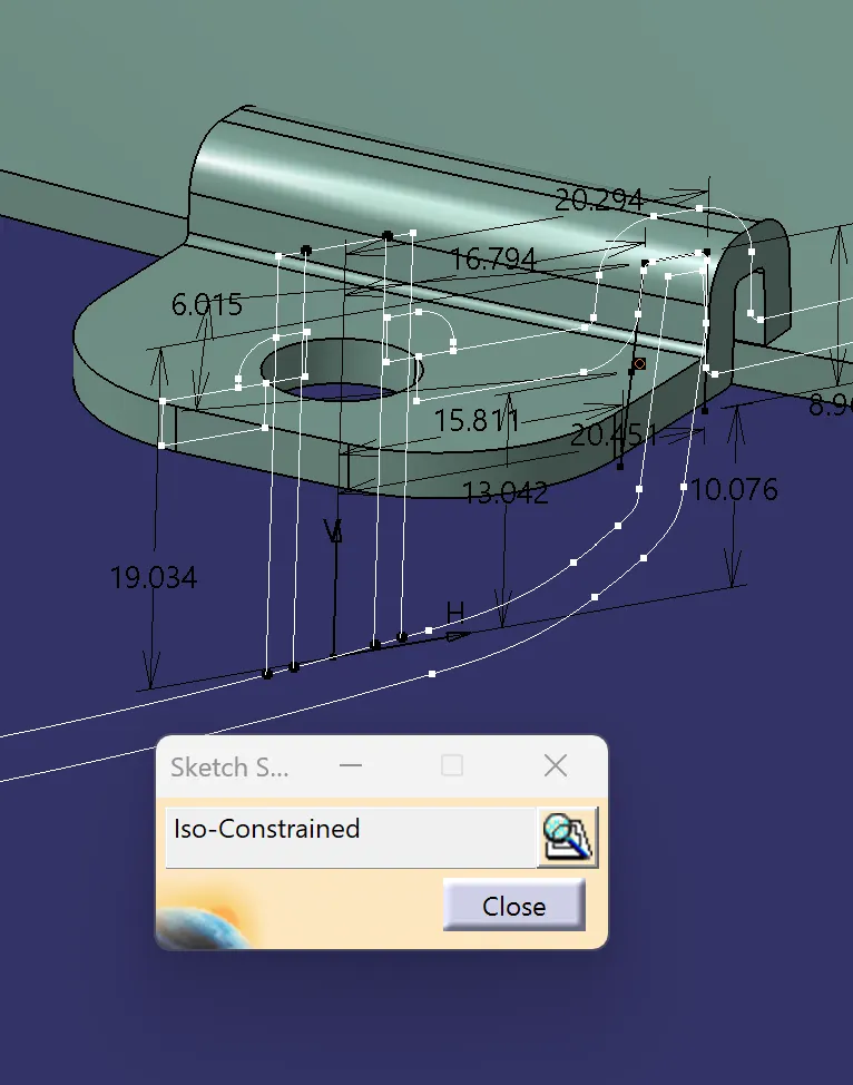
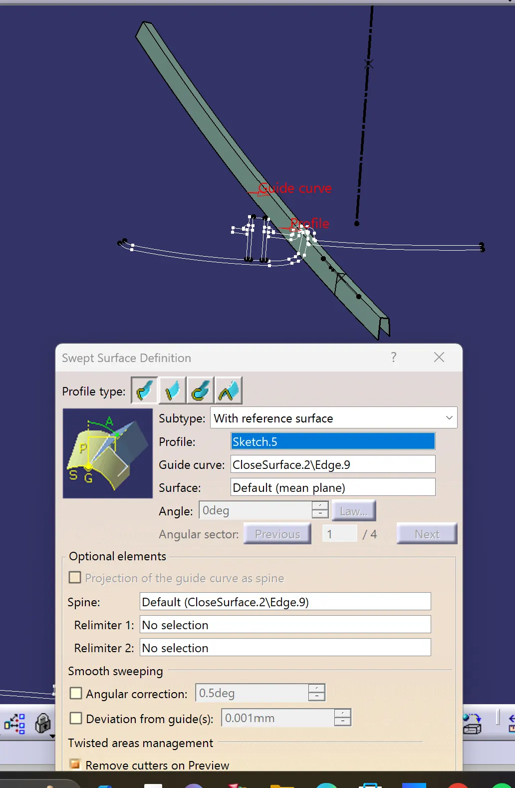
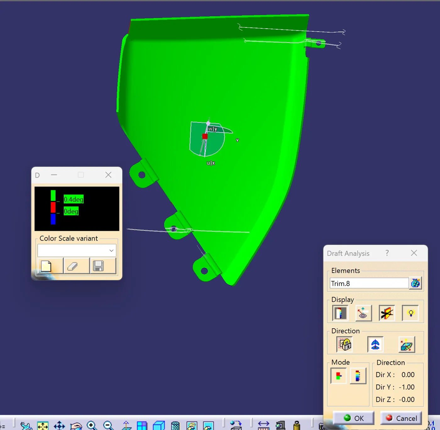
FROM THE SAME ABOVE MENTIONED STEPS WE NEED DESIGN THE FLANGES FOR THE BOTTLE HOLDER,BUT WE DOESENT HAVE THE MASTER SECTION SO WE NEED TO CREATE THE FLANGES AS SAME.
DRAFT ANALYSIS ALONG MAIN TOOLING AXIS:
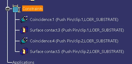
WE NEED PROVIDE THE ASSEMBLY CONSTRAINTS FOR THE DOG HOUSE AND THE PUSH PIN:
- CREATE AXIS LINE FOR THE BOTH
- PROVIDE THE AXIS TO AXIS CONSTRAINT
- PROVIDE THE TOUCH CONSTRAINT
- FOT THE BOTH DOG HOUSE
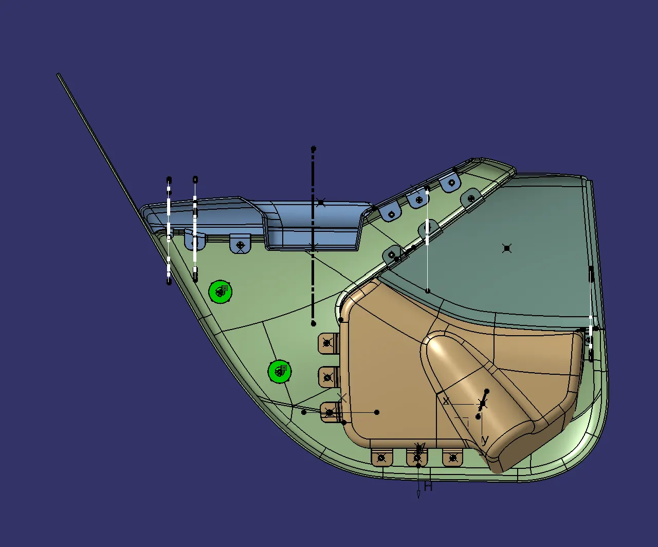
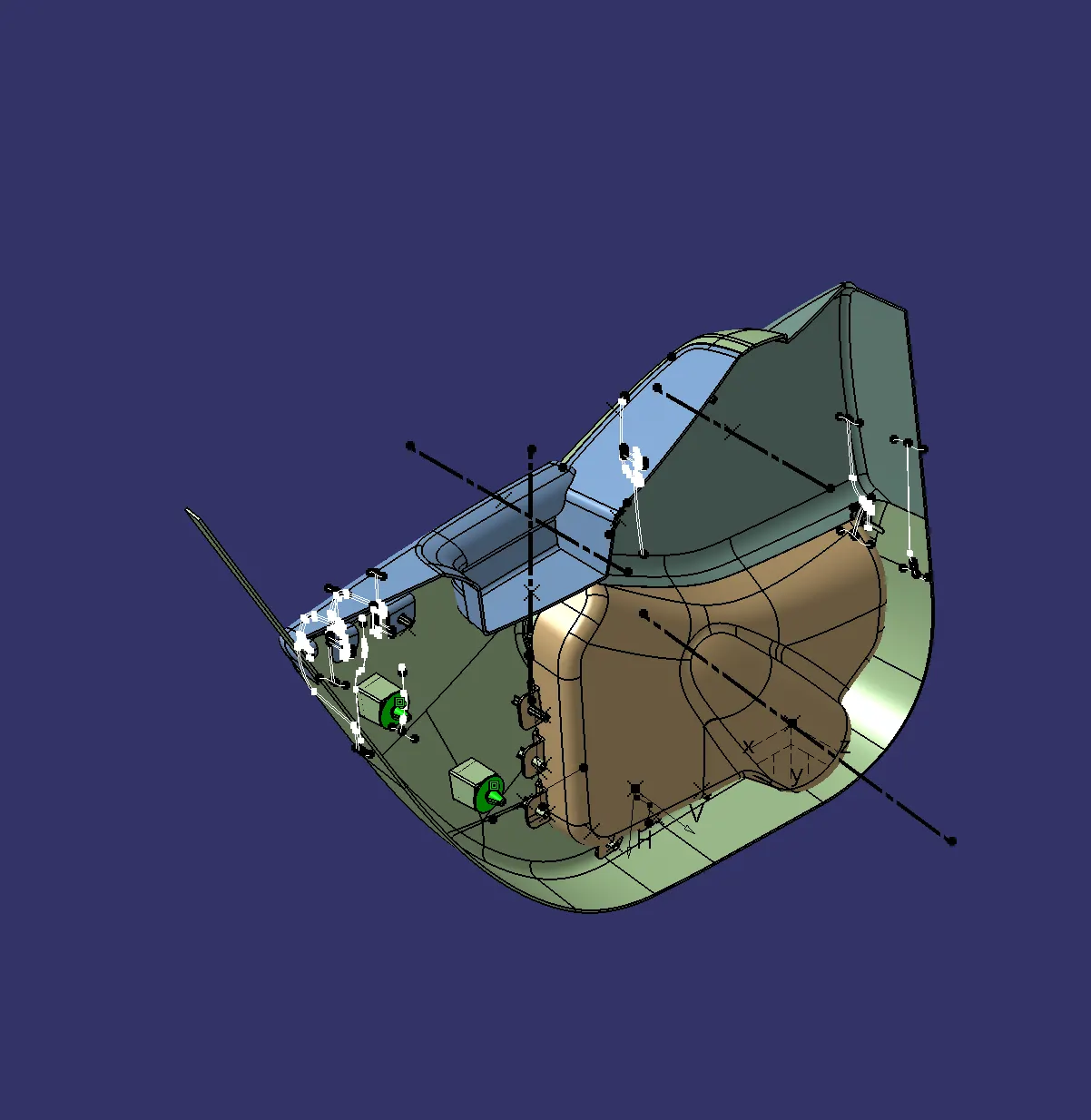
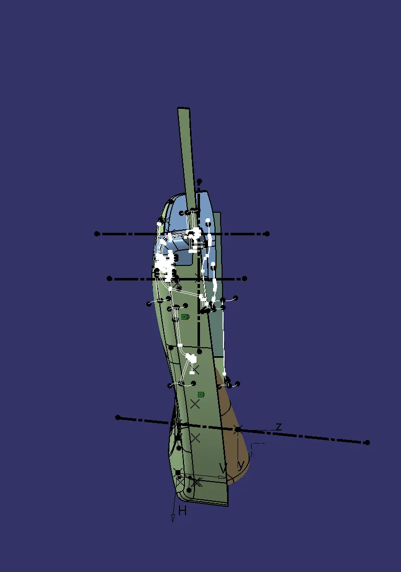
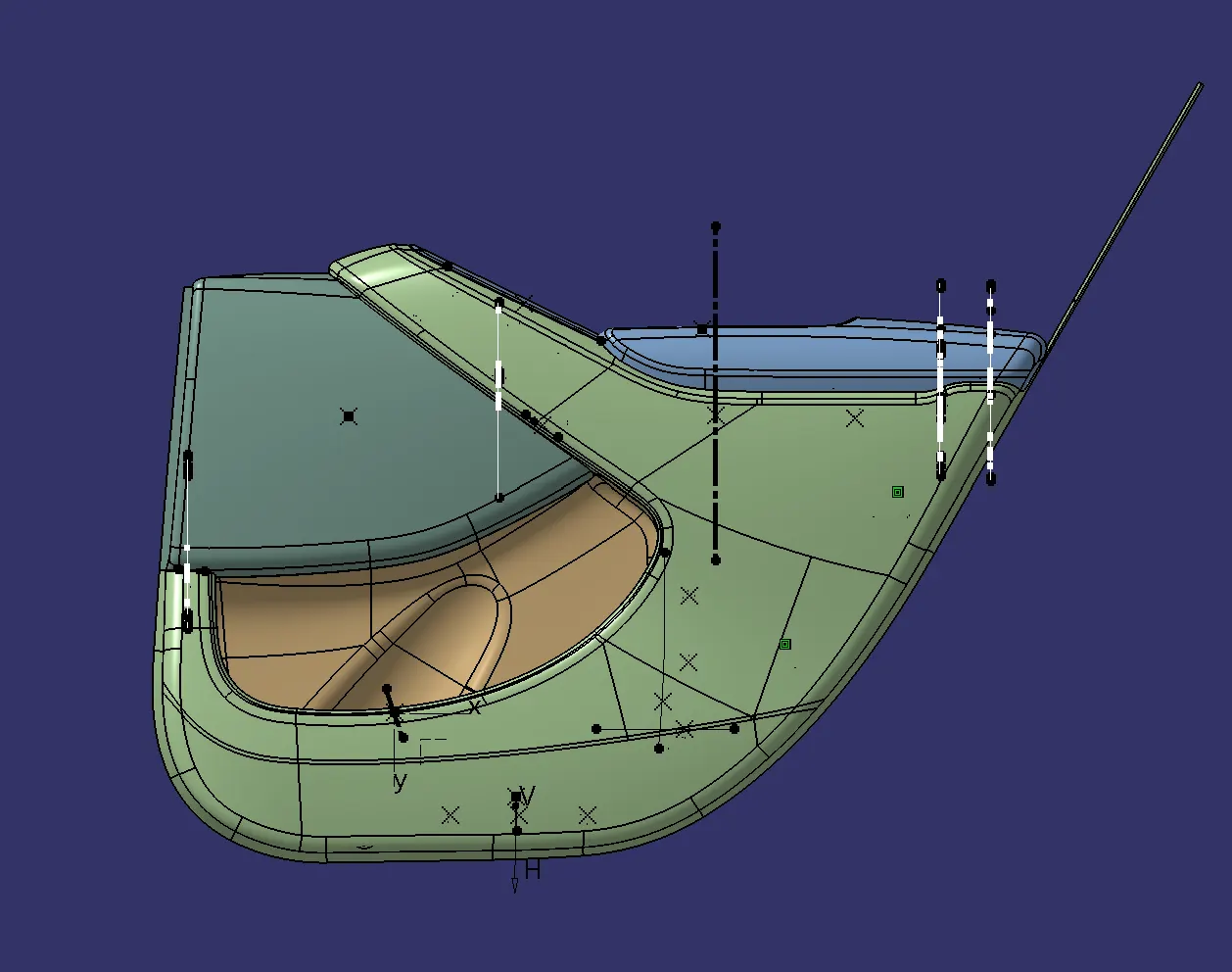
FINAL DOOR TRIM PRODUCT WITH MULTIPLE VIEWS:
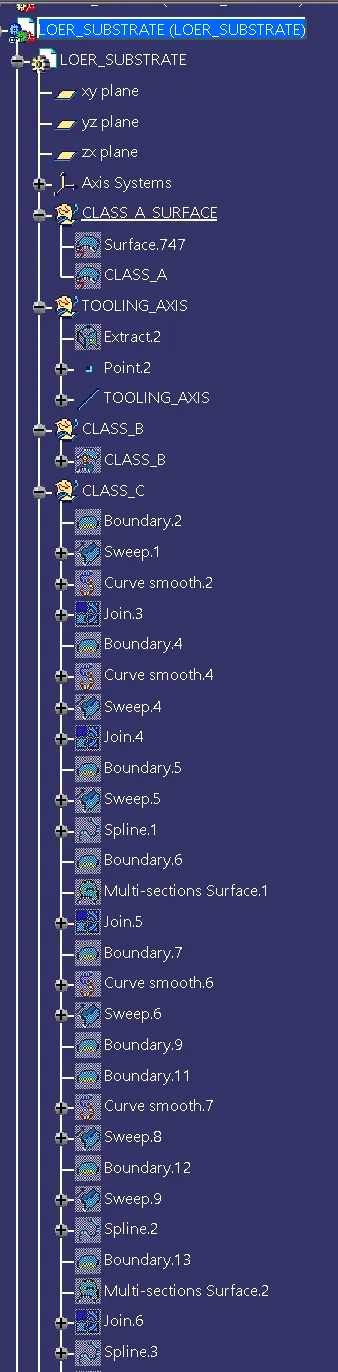
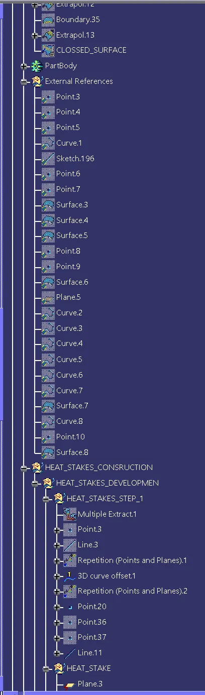
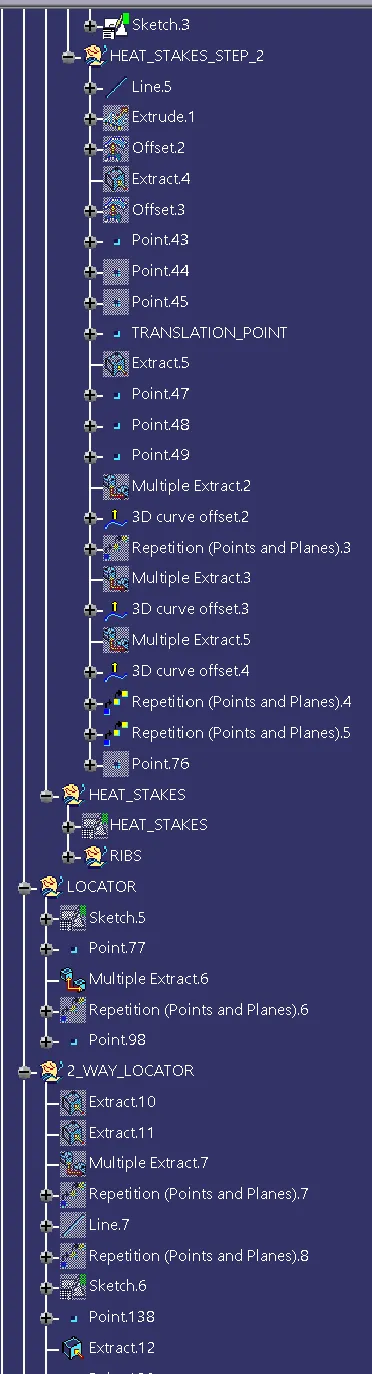
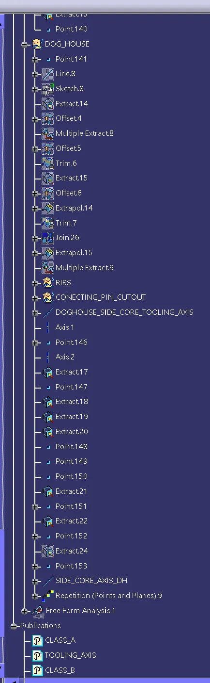
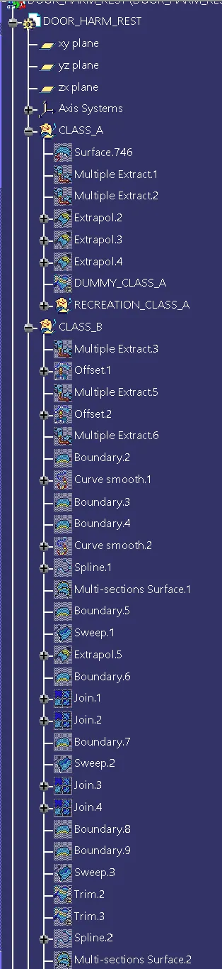
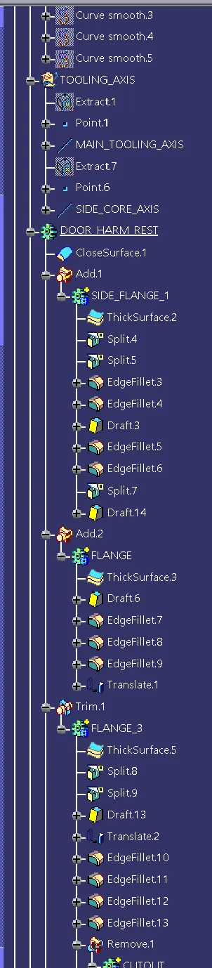
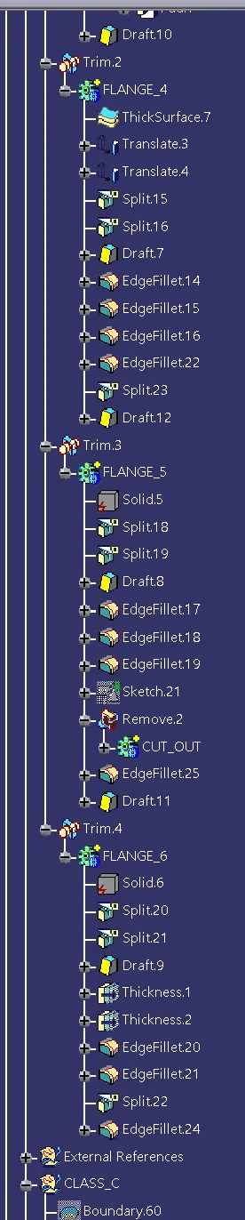
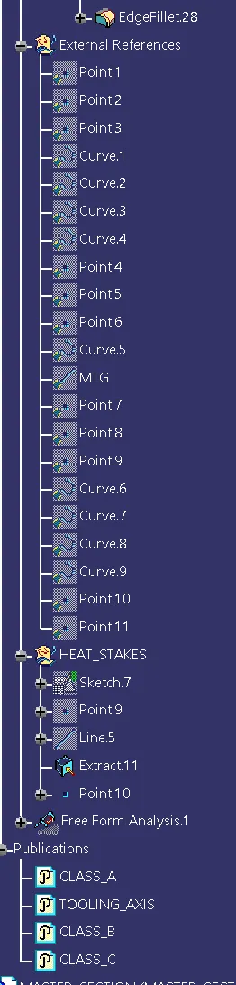
TREE STUCTURE:
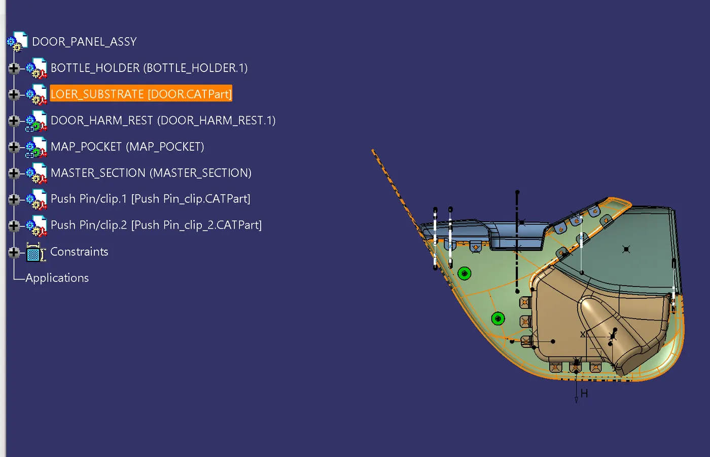






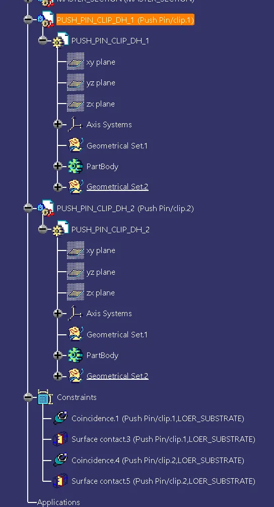
CONCLUTION:
The Design of The Automotive Door Trim Panel from a Class A surface to a Closed Part Body with all the necessary attachment features by following all the design rules using CATIA V5 is done Successfully and all the required CATPart and CATProduct files are attached.