Week 12- Final project
DOOR TRIM PANAL
AIM:-
Creation of CAD model considering following inputs as like in OEM and tier1 companies
a) Class A surface
b) Nominal thickness: Refer to master sections
c) Attachment strategy :
Use Pushpin with Dog house for Lower substrate – Door panel attachment
Use heat stakes for a part to the part attachment
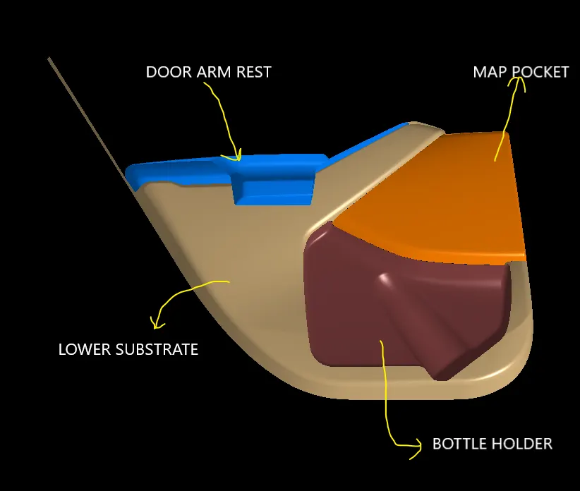
In this project we need to design four parts of the door trim using the master sections provided, namely
- Door Arm Rest
- Lower Substrate
- Bottle Holder
- Map Pocket
LOWER SUBSTRATE
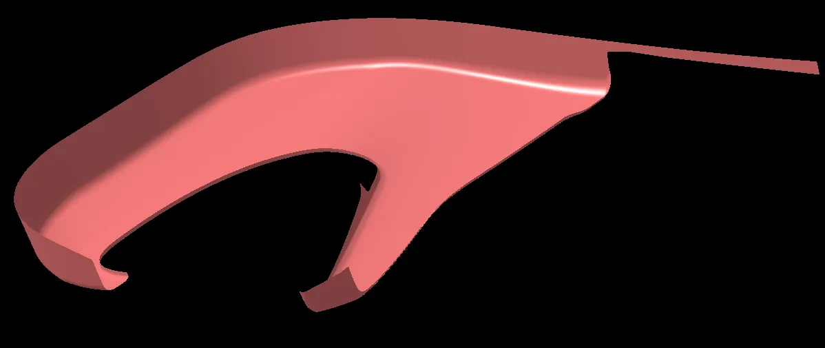
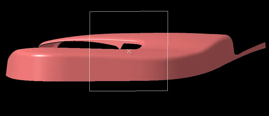
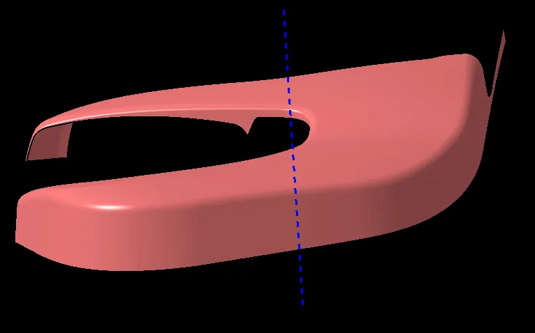
GIVEN CLASS A SURFACE
CRETION OF TOOLING AXIS
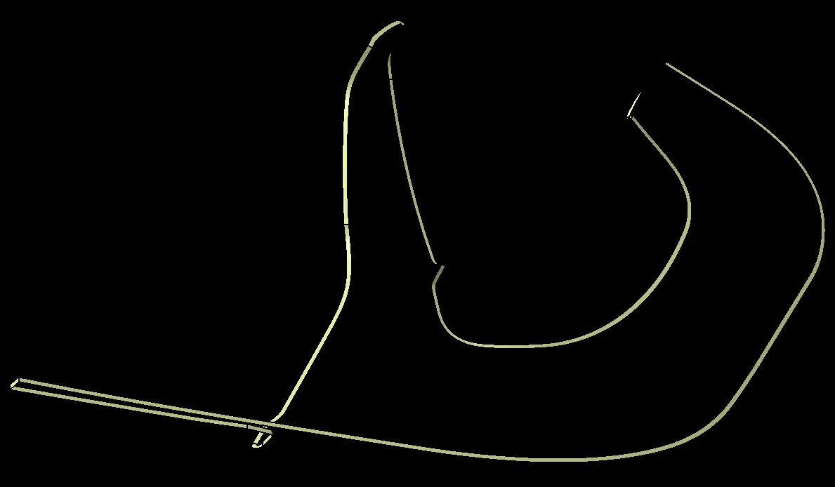
- create a point at center of gravity of given surface and at that point create XY plane
- now take intersection between class A and the plane that we created above
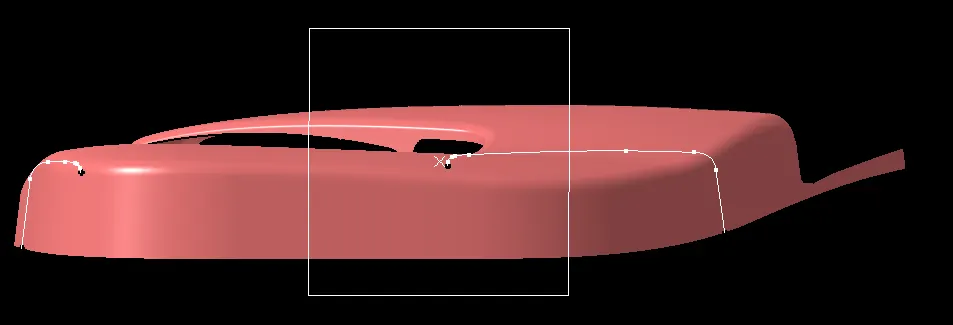
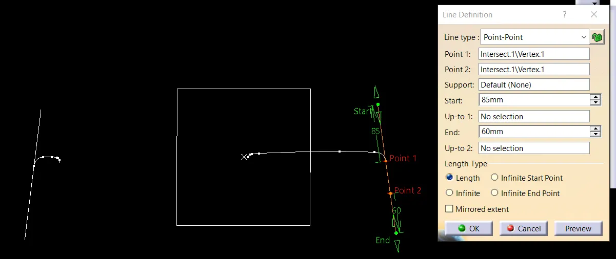
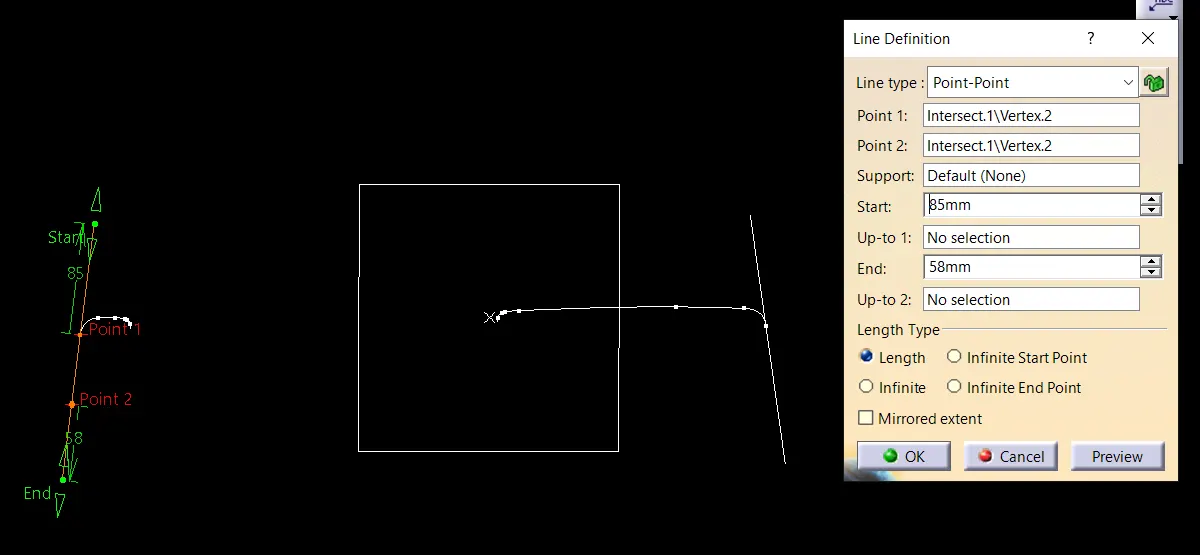
- create 2 lines as shown below with the help of intersection
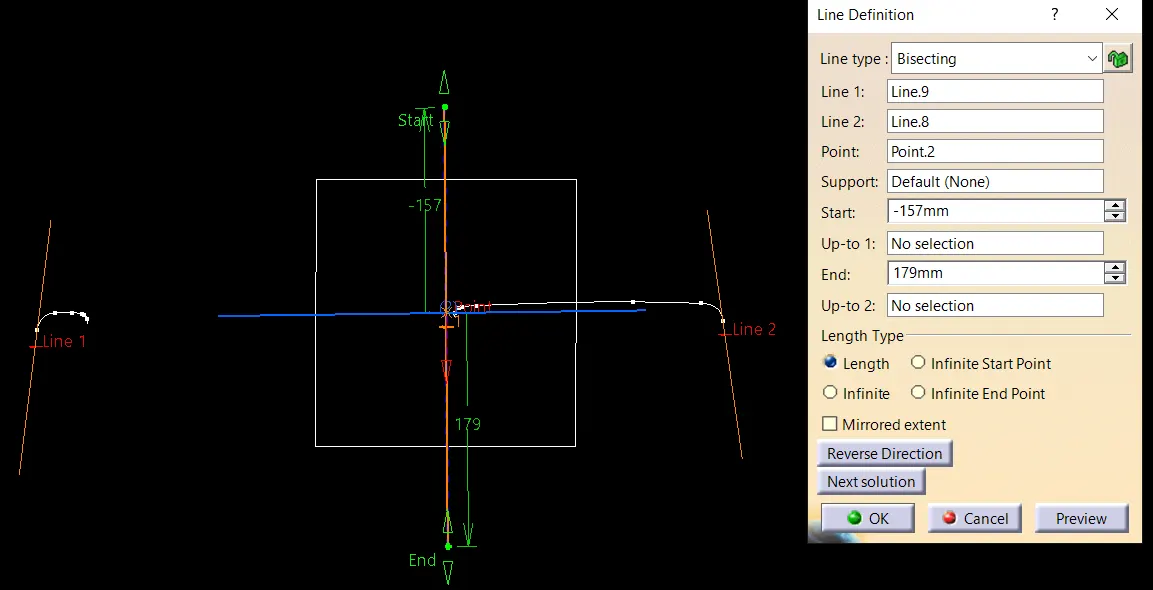
- create a bisecting line where the two lines and point will be selected as inputs this line will be the MAIN TOOLING AXIS
CLASS B SURFACE
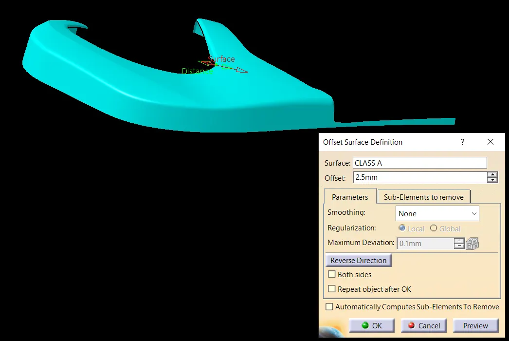
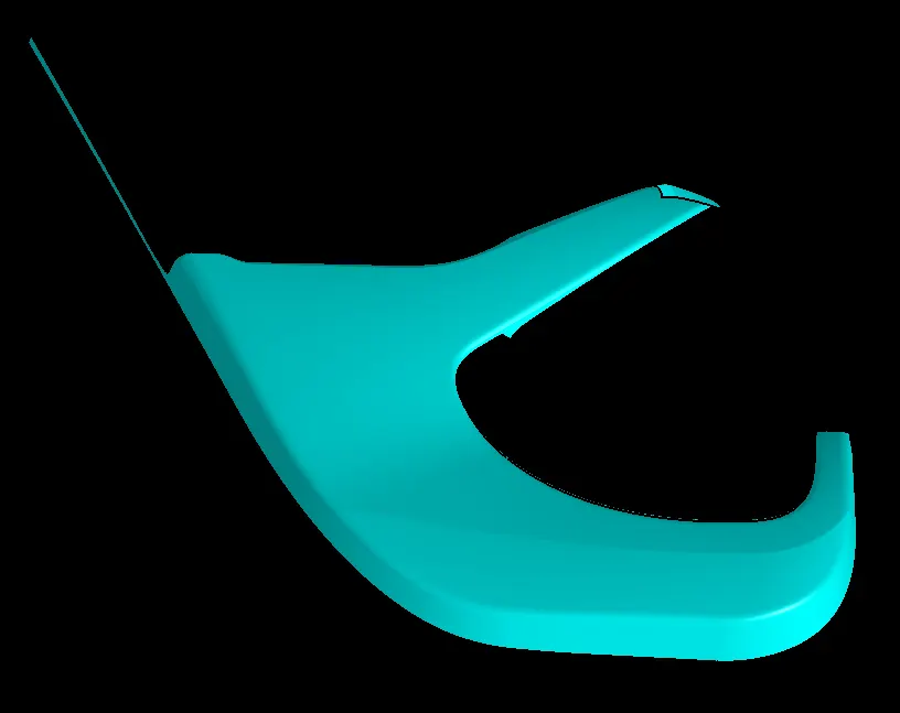
To create CLASS B SURFACE take offset of 2.5mm from CLASS A
CLASS C SURFACE
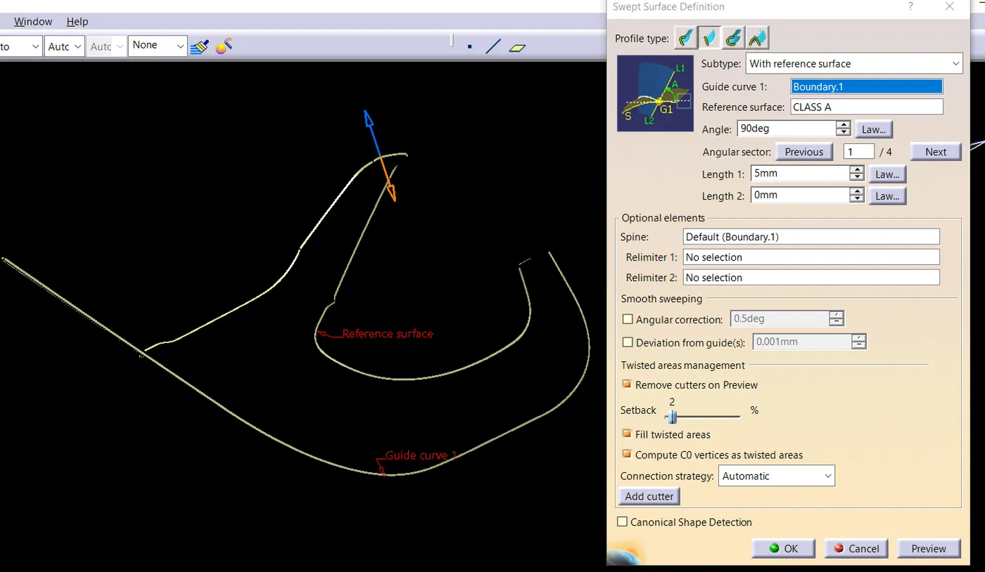
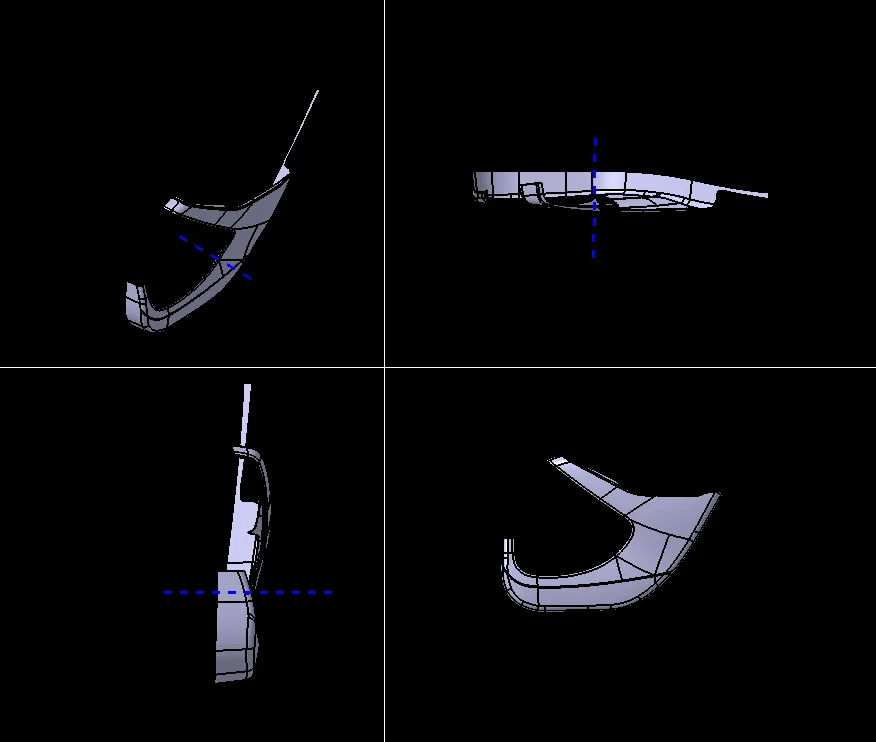
Create class C surface with sweep command
SOLID SURFACE
DRAFT ANALYSIS
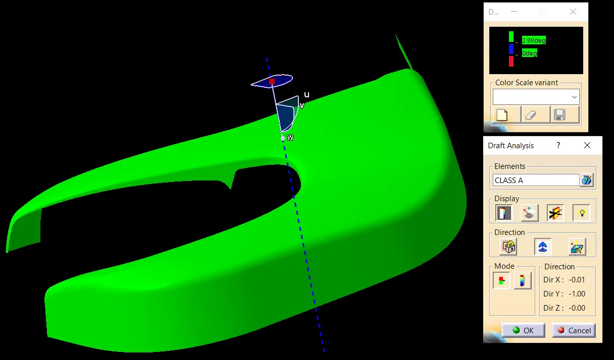
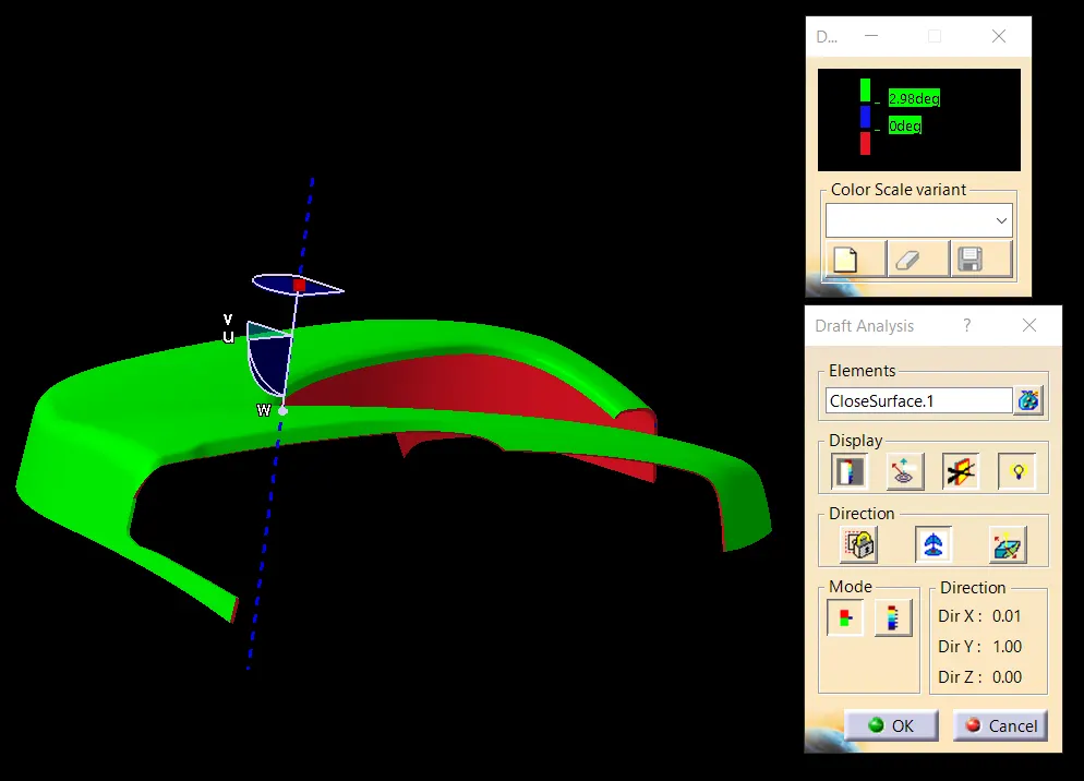
This analysis tells us whether our component will be safely ejected in the tooling axis we have provided. Draft analysis shows color codes which are defined by the user for different values and the values are also defined by the user. These colors help us to analysis if the component is clearing the analysis or not
After creating a tooling axis we do the draft analysis. Before drafting we have to make sure that in the view mode it is selected for the materials.
After selecting the feature draft analysis tool we drag the compass from its position to the tool axis. Then lock the compass. After that select anywhere on the component and it will give you the result.
CLASS A
We change the minimum draft for the component to 3°
here All areas are within minimum draft value
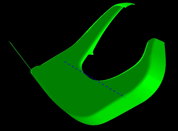
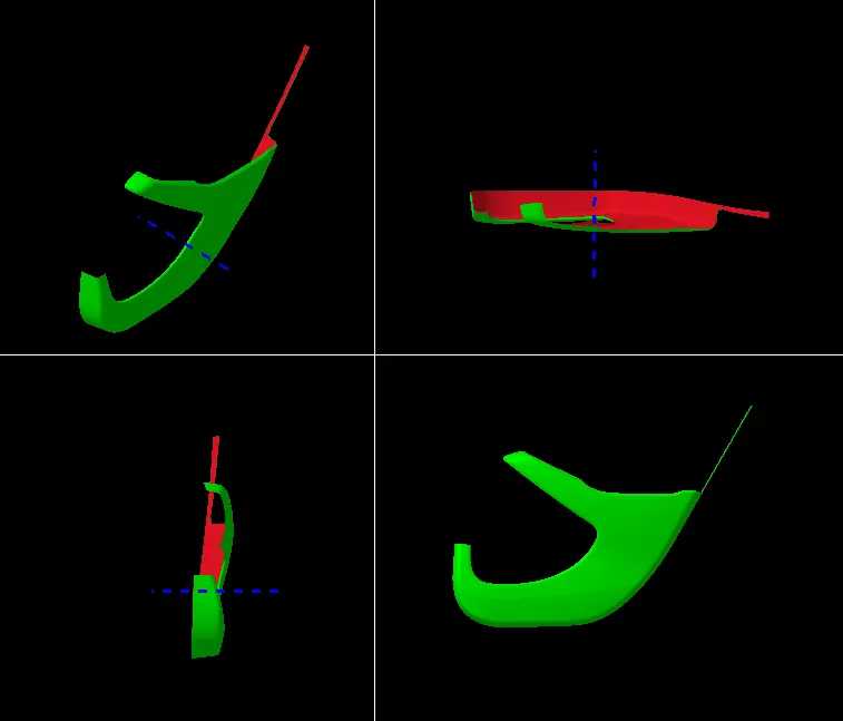
DRAFT ANALYSIS OF SOLID PART
all surfaces clearing the draft of 3 degrees
CREATION OF DOG HOUSE
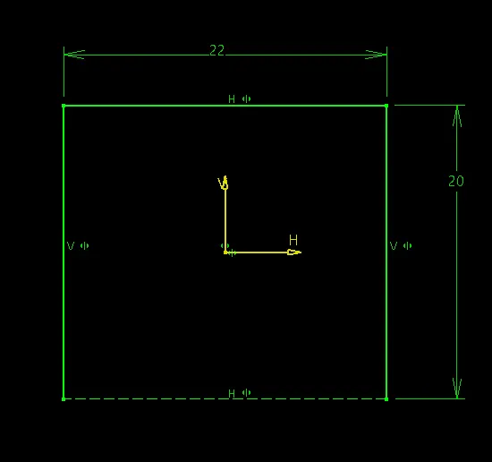
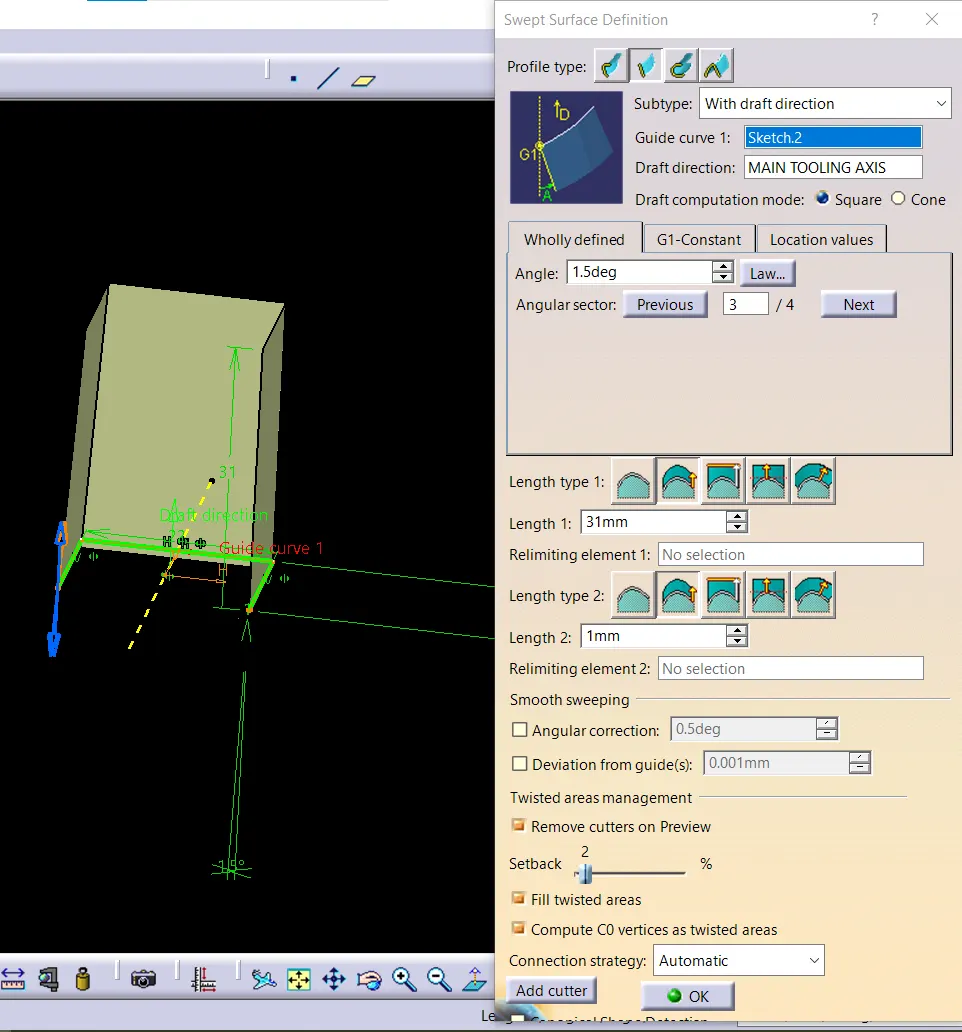
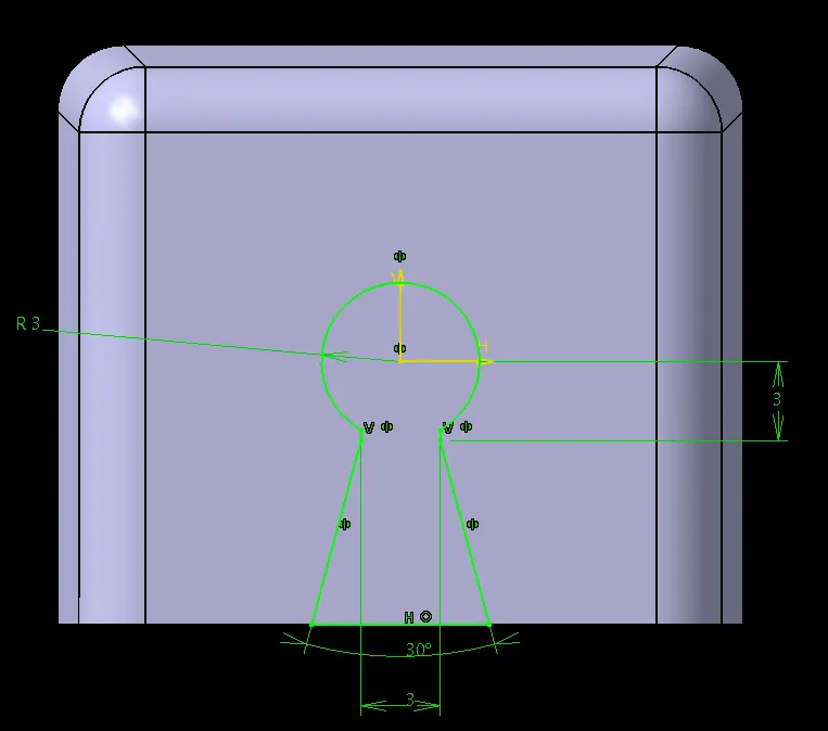
- The sketch is swept in the draft direction with 1.5 degrees.
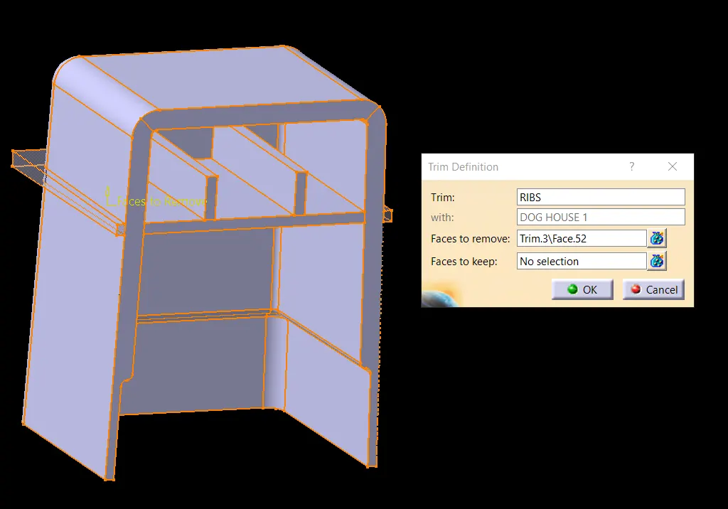
- The base surface is offset and trimmed to form a cube with no front face.
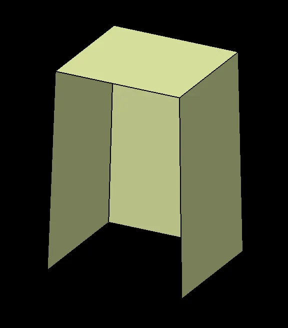
- convert it into solid by using thick surface command
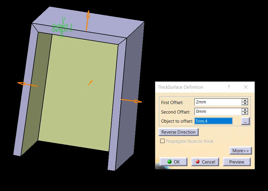
CREATION OF SIDE CORE AXIS
outside surfaces of dog house will be clear with main tooling axis but for inside surfaces to be clear in draft analysis we need to create side core axis
Inside walls of the dog house was drafted with side core axis as pulling direction at 0.5 degrees draft angle
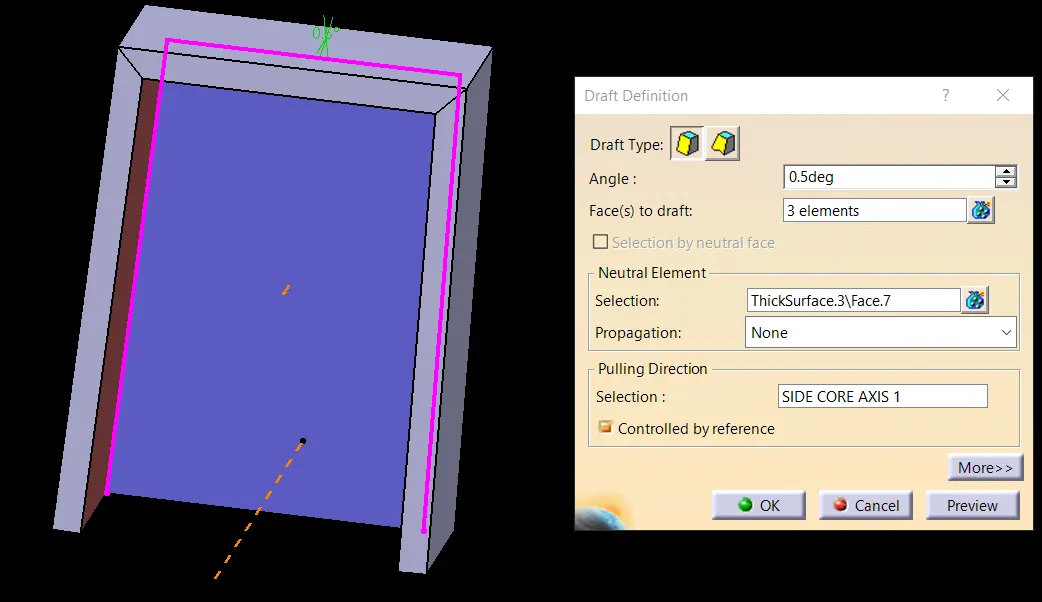
to avoiding sink marks
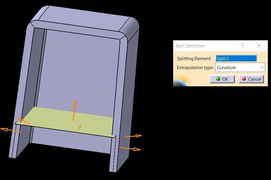
attaching ribs to dog house
top profile of dog house
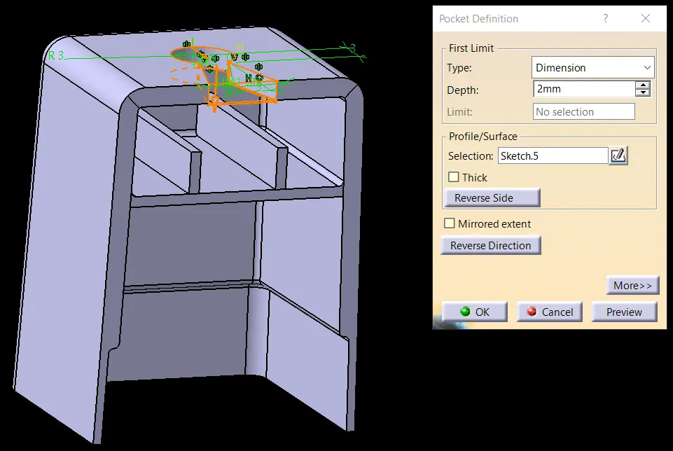
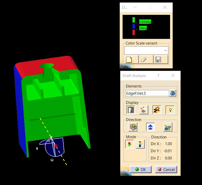
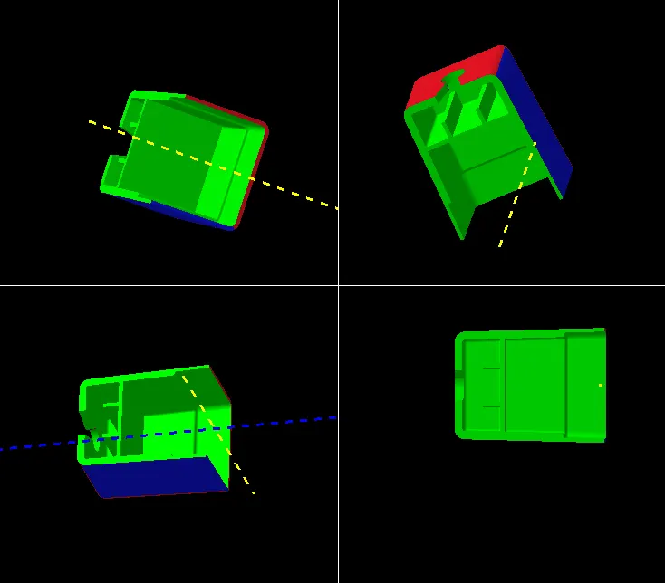
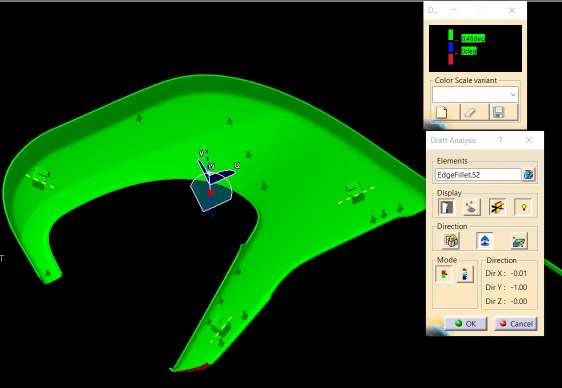
DRAFT ANALYSIS OF DOG HOUSE
outside surfaces cleared with 1.45deg draft with main tooling axis
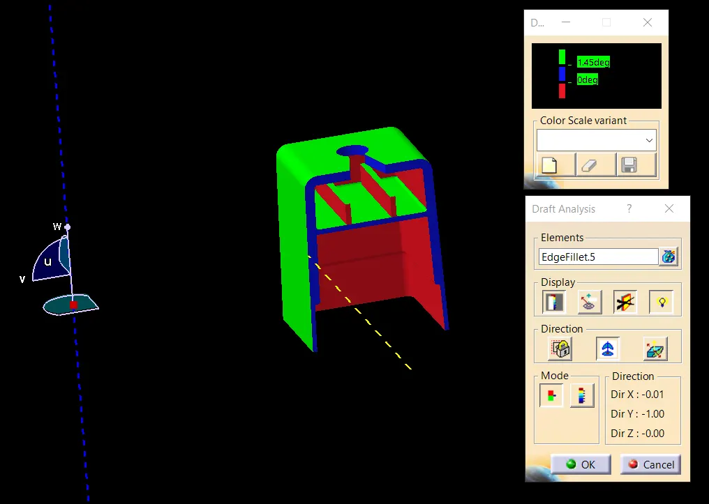
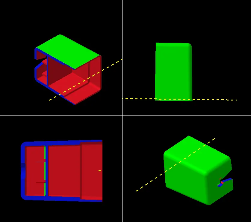
inner surfaces will be clear with 0.48deg draft with side core axis
DESIGN OF HEAT STAKES
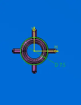
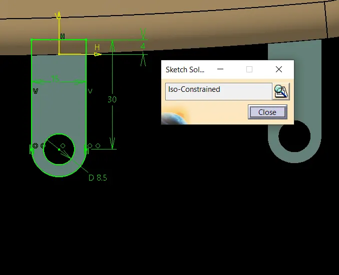
- create a sketch according to the given master section here i create a circle of outer dia 7.5mm
- pad it with thick check box on and give thickness value 1.5mm
- provide draft to inner and outer surface of 0.5deg and select pulling direction as the main tooling axis of lower substrate
- give fillet of radius 0.25mm
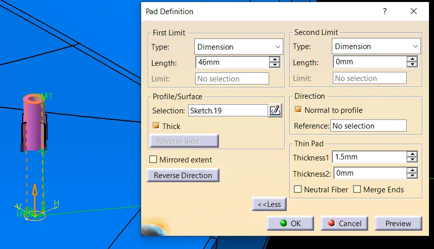
design of Boss gussets (rib like structure giving strength to the screw boss) must meet ribs guidelines
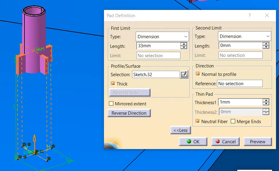
- provide draft of 0.5deg to each wall with pulling direction as main tooling axis of lower substrate
- give fillet to edges of radius 0.25mm
DRAFT ANALYSIS OF FINAL PART WITH HEAT STAKES AND DOG HOUSE
FOR DRAFT VALUE 0.48deg with main tooling axis
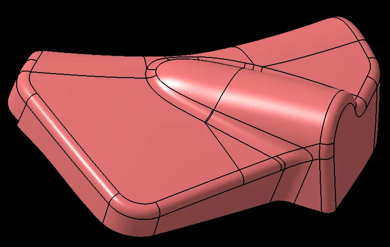
BOTTLE HOLDER
GIVEN CLASS A SURFACE
CREATION OF TOOLING AXIS
- create a point at center of gravity of given surface and at that point create XY plane
- now take intersection between class A and the plane that we created above
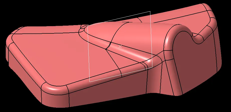
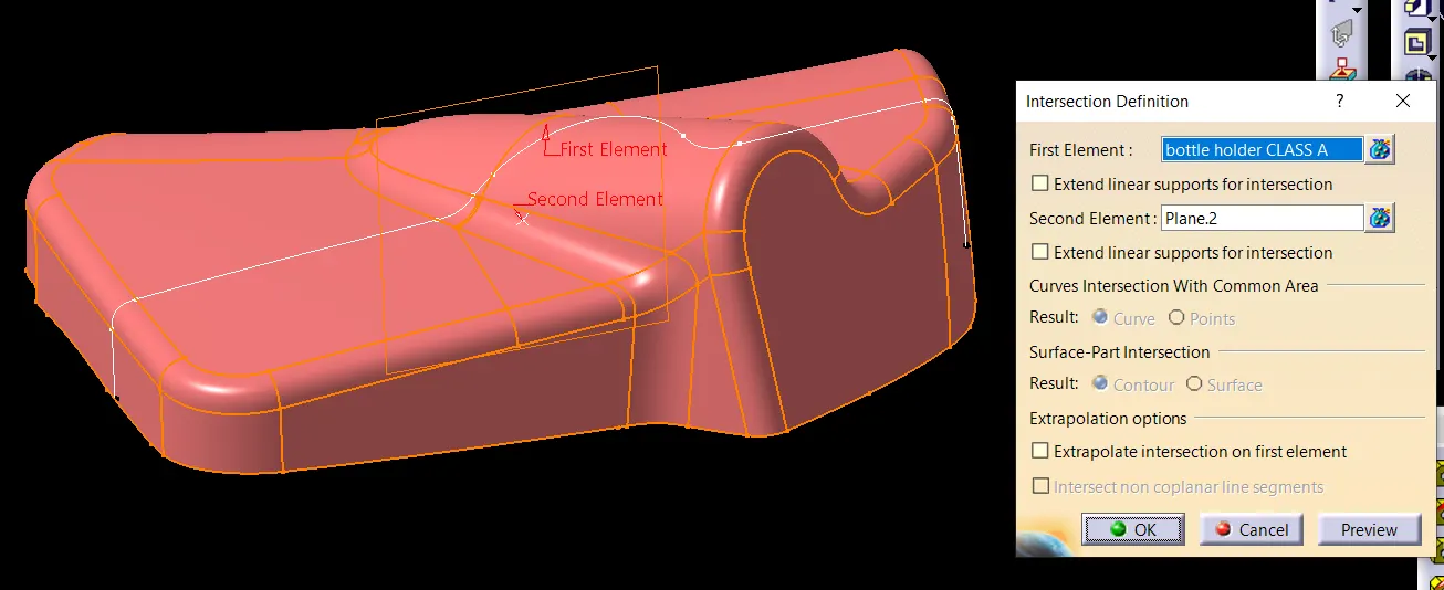
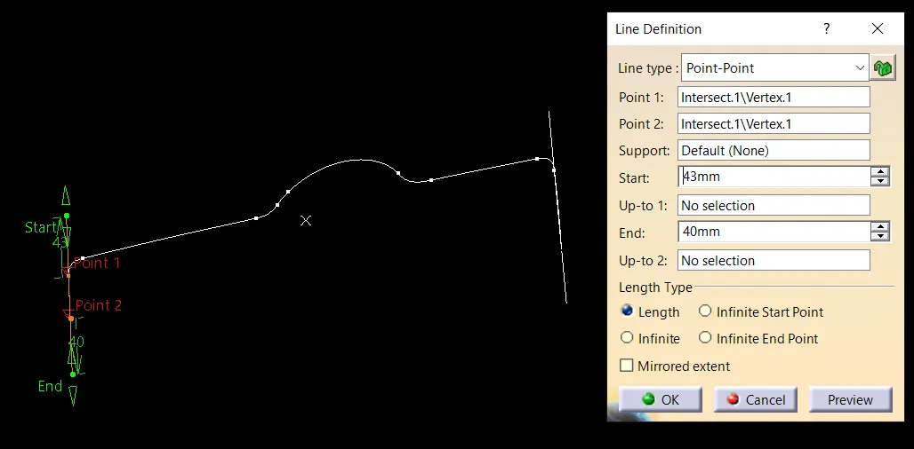
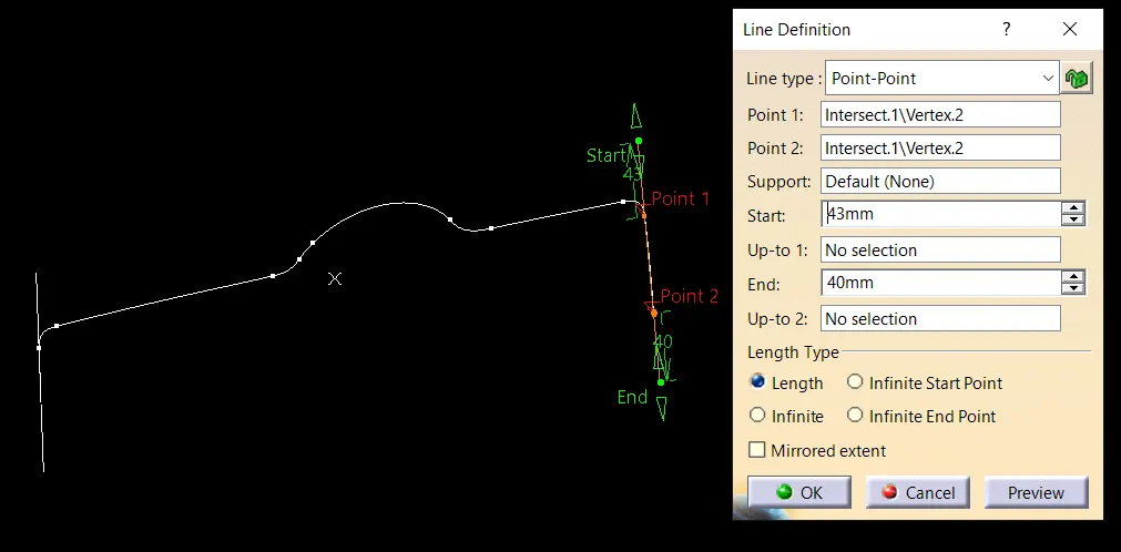
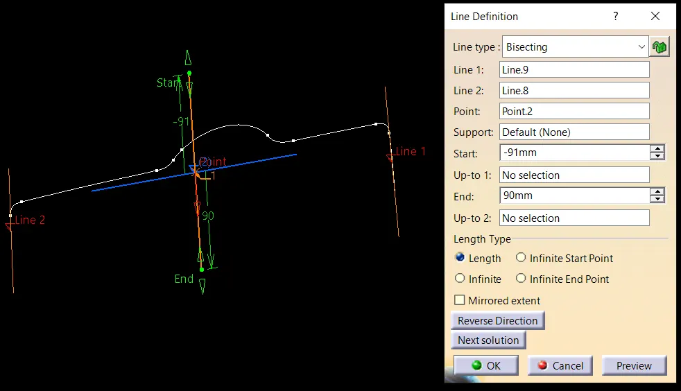
- create 2 lines as shown below with the help of intersection
- create a bisecting line where the two lines and point will be selected as inputs.
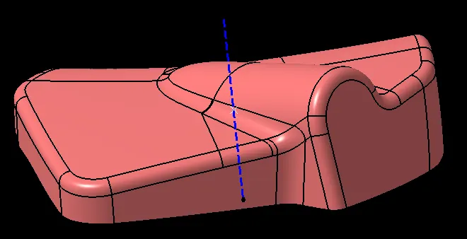
- now we do draft analysis with above created bisecting line here i slightly inclined the bisecting line in order to minimizing the patches which is not cleared in draft analysis and lock the compass the create a new line at the same position as of inclined line and name this line as main tooling axis
CLASS B SURFACE
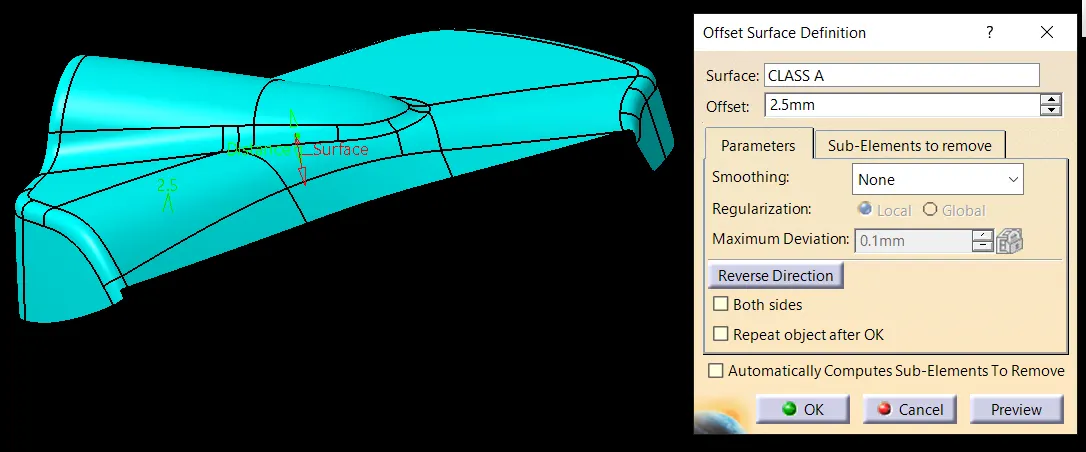
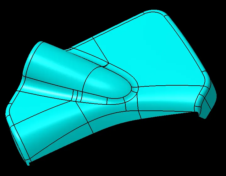
To create CLASS B SURFACE take offset of 2.5mm from CLASS A
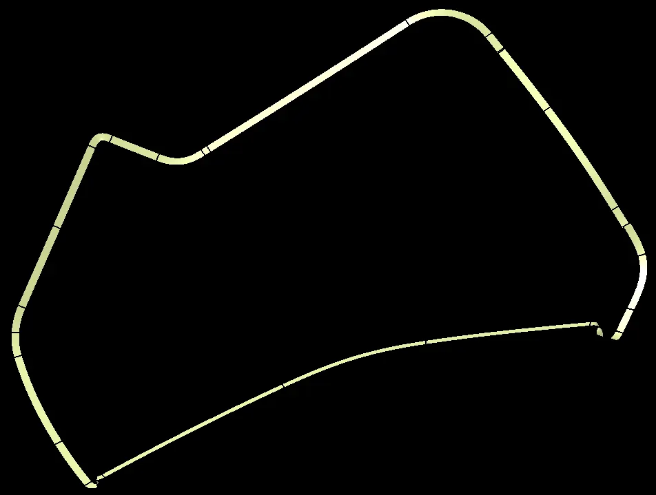
CLASS C SURFACE
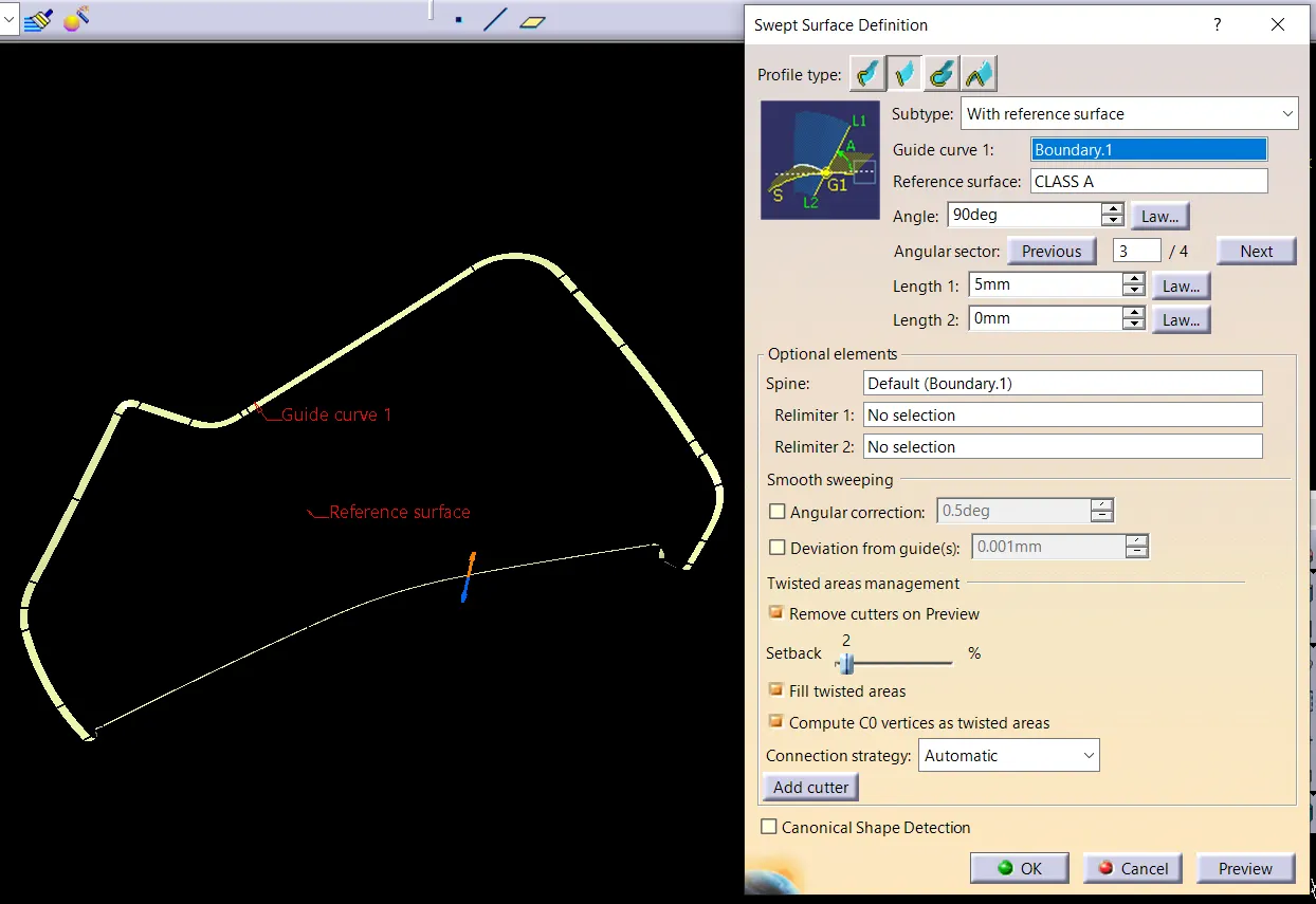
Create class C surface with sweep command
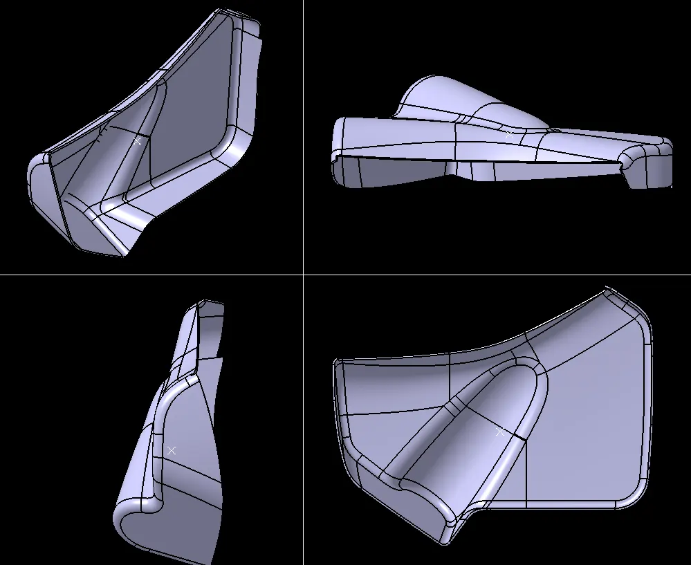
SOLID PART
DRAFT ANALYSIS
CLASS A
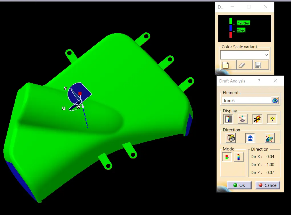
FOR DRAFT VALUE 3 DEGREE
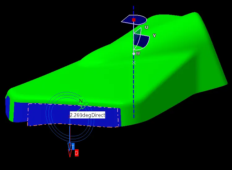
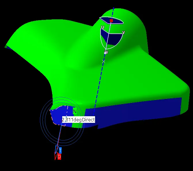
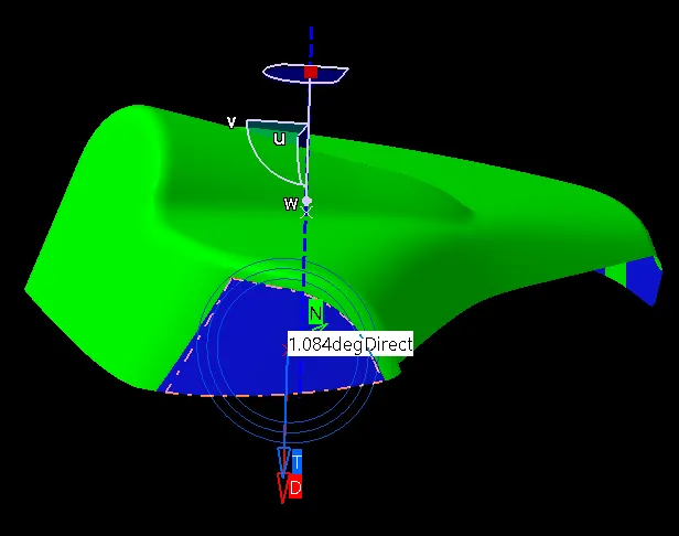
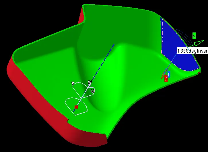
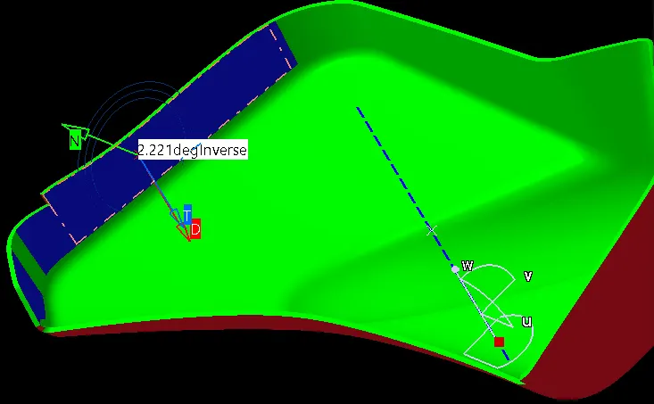
all the green areas means the draft angle is above 3 degrees and it is feasible to manufacture the component. but there are some blue patches which needs to be improved
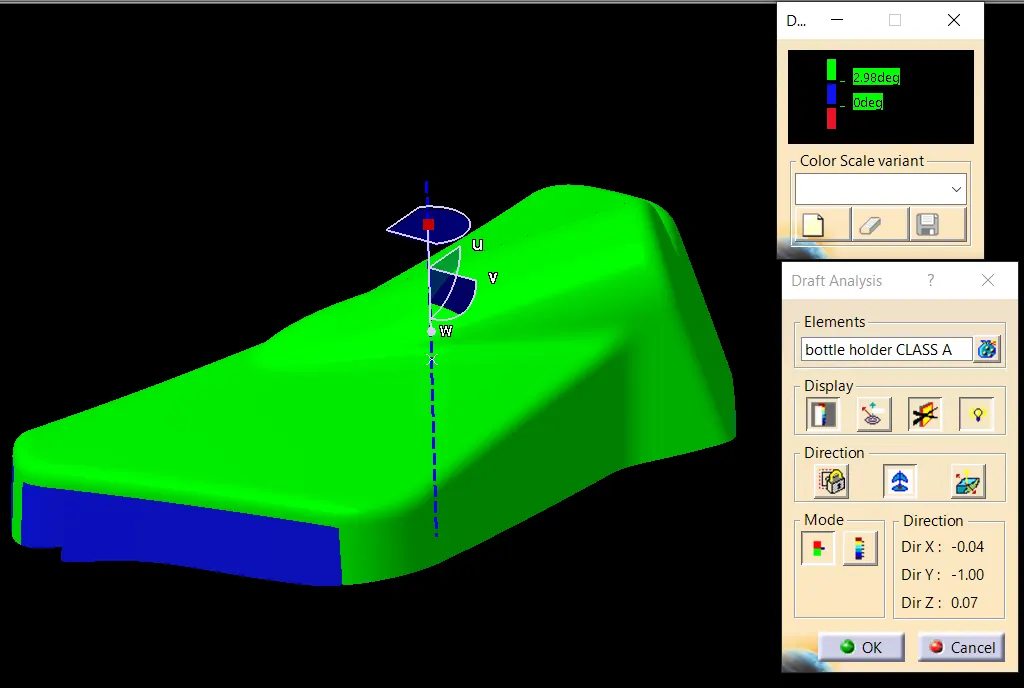
patches with minimum draft value on them
CLASS B
FOR DRAFT VALUE 3 DEGREE
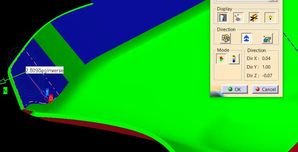
since class B is the offset of class A so same patches will also occure in class B
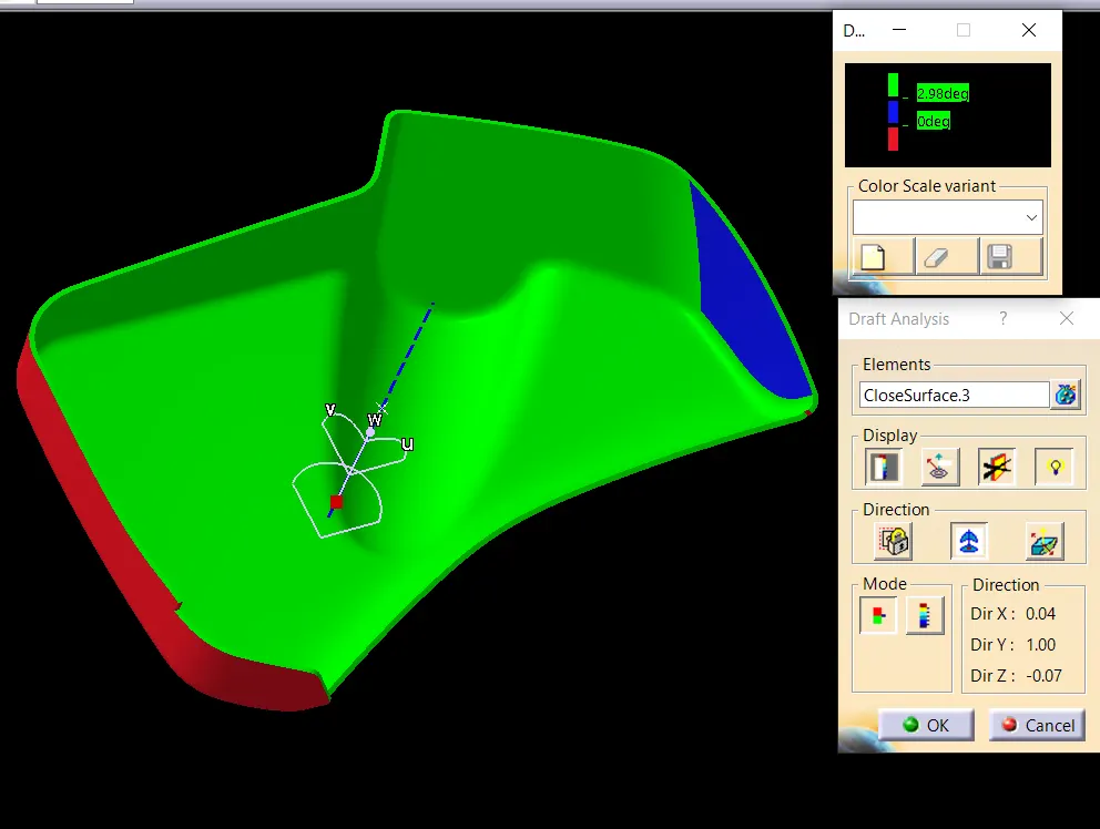
patches with minimum draft value on them
CLASS C
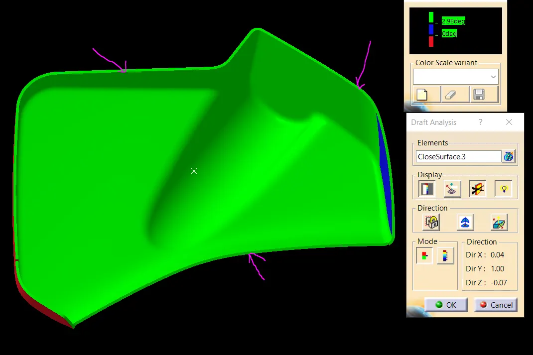
WITH DRAFT VALUE 3 DEGREE
all areas are within minimum draft value
ADD FLANGE TO MAIN COMPONENT
FINAL PART DRAFT ANALYSIS WITH DRAFT VALUE 3DEG
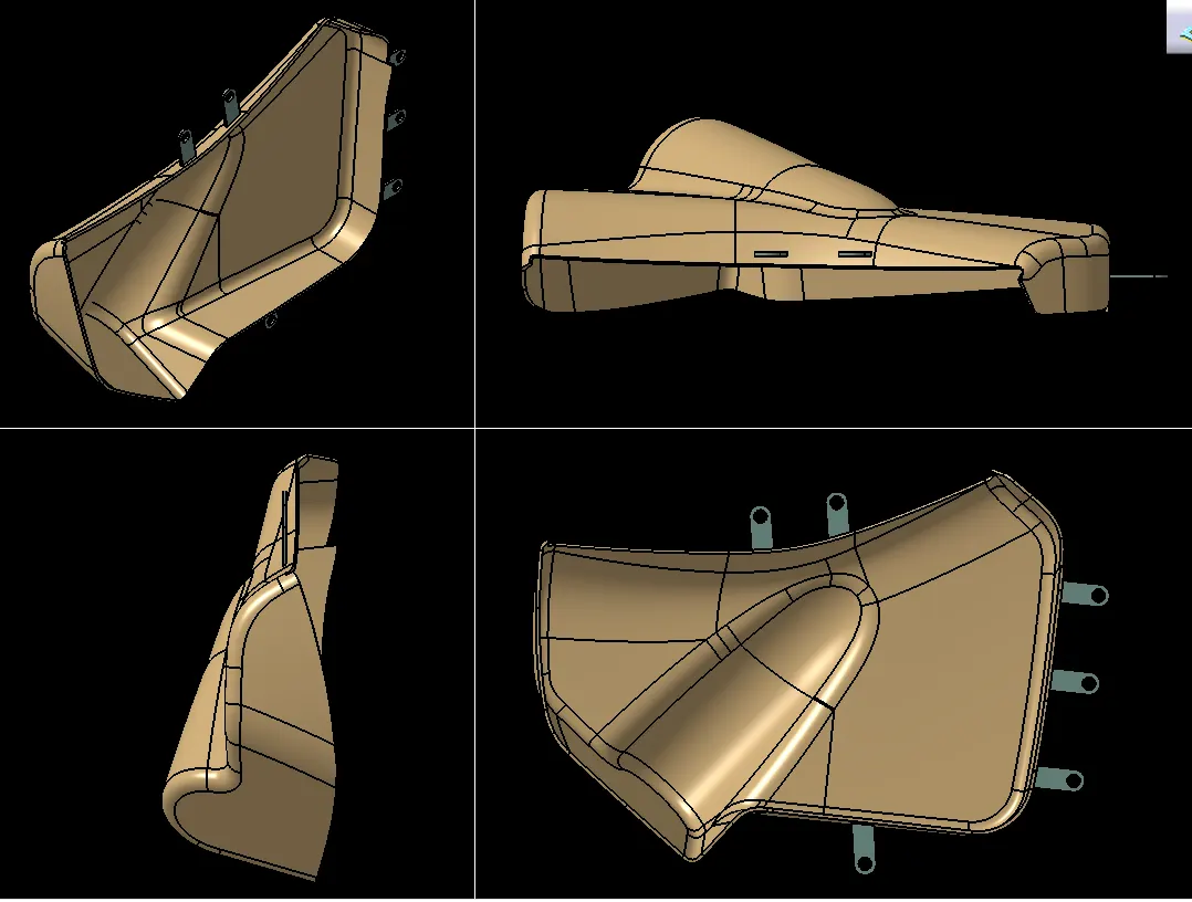
DIFFERENT VIEWS
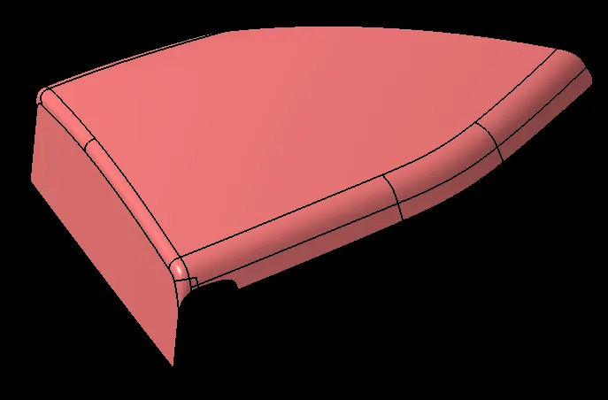
MAP POCKET
GIVEN CLASS A SURFACE
CREATION OF TOOLING AXIS
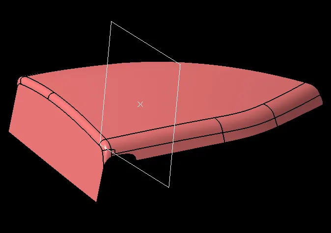
- create a point at center of gravity of given surface and at that point create YZ plane
- now take intersection between class A and the plane that we created above
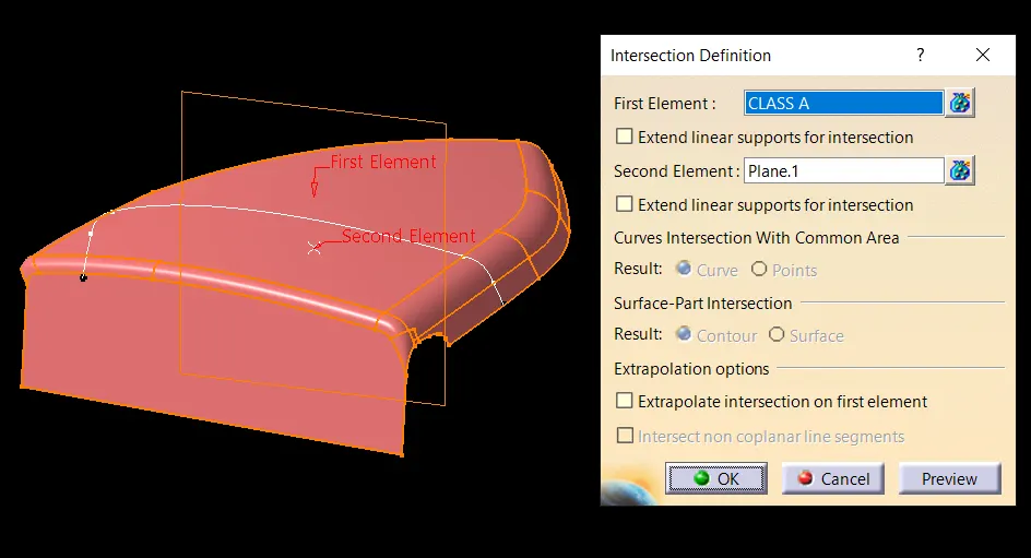
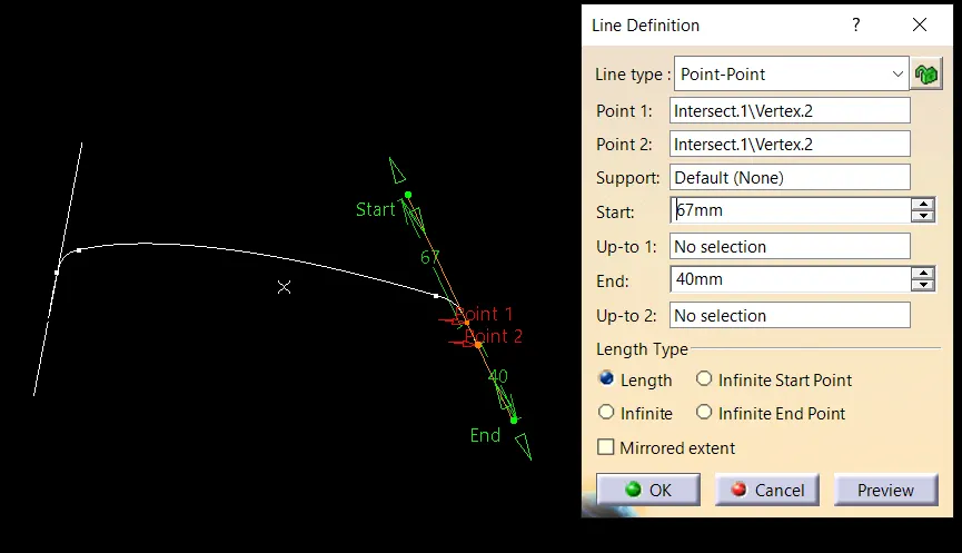
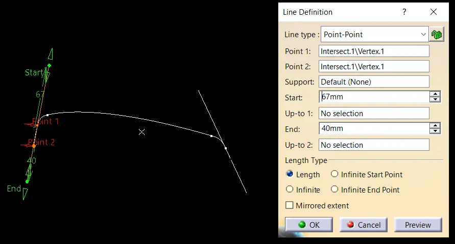
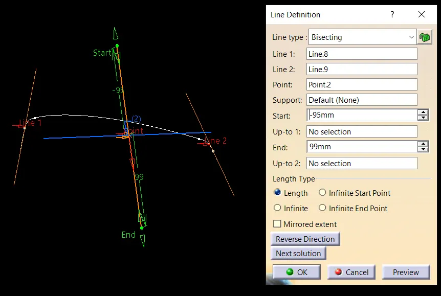
- create 2 lines as shown below with the help of intersection
- create a bisecting line where the two lines and point will be selected as inputs.name this line as main tooling axis
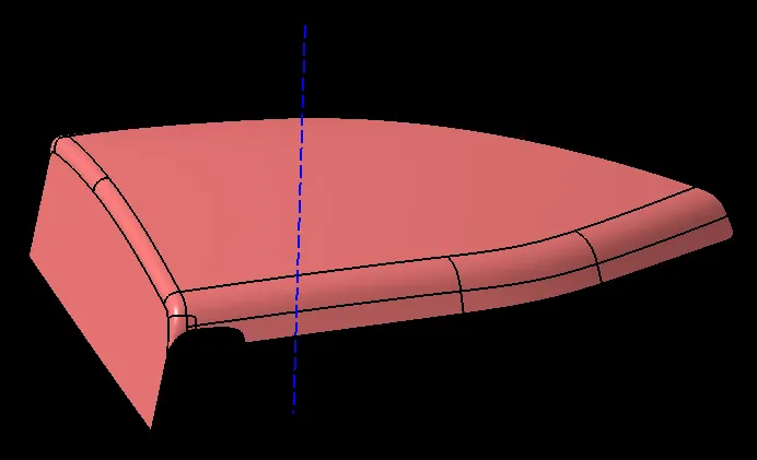
CLASS B SURFACE
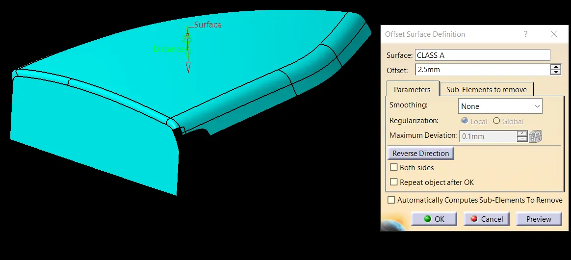
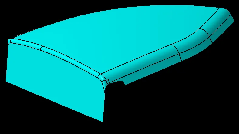
To create CLASS B SURFACE take offset of 2.5mm from CLASS A
Missing surfaces are created with the help of multi section command
CLASS C SURFACE
Create class C surface with sweep and muti section command
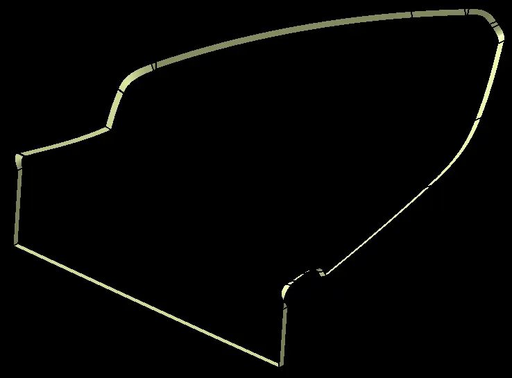
SOLID PART
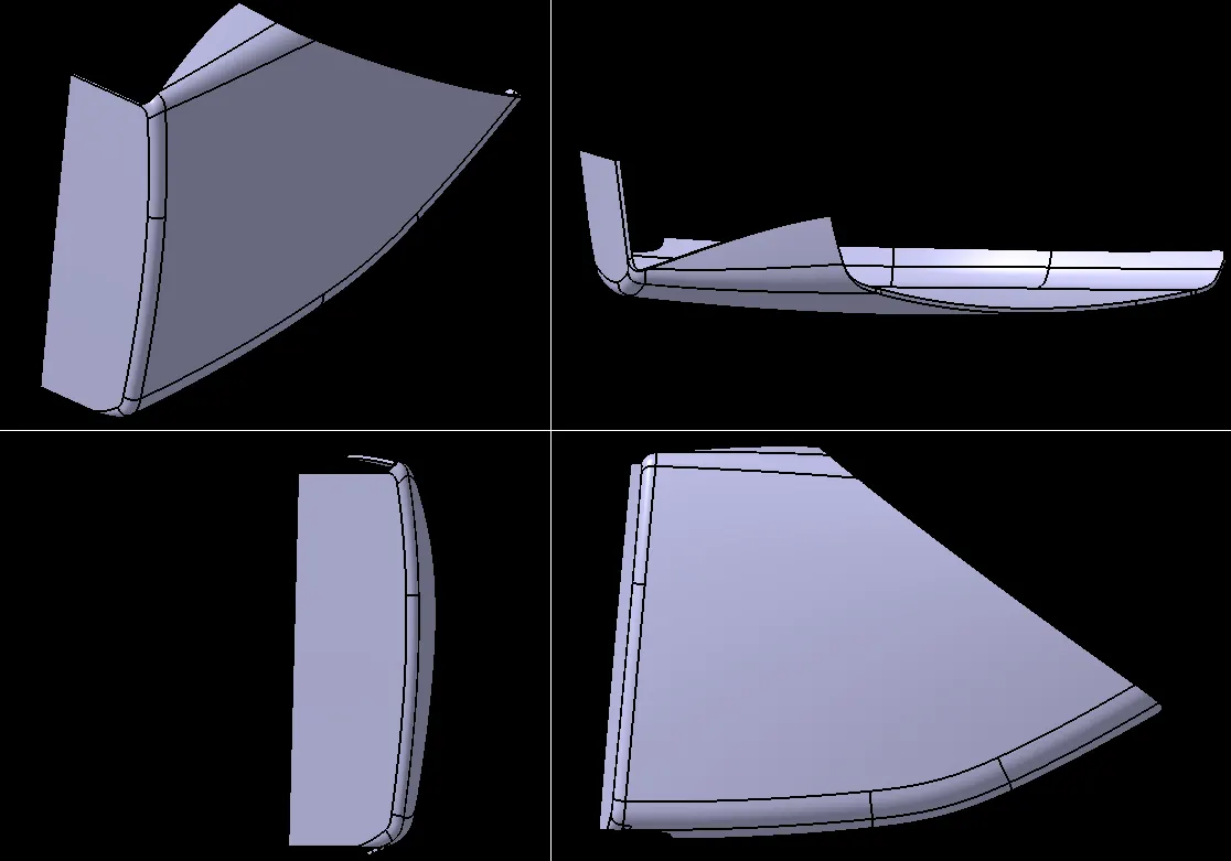
DRAFT ANALYSIS
CLASS A
with draft value 3deg
entire surface shows the green that means the draft angle is above 3 degrees and it is feasible to manufacture the component.
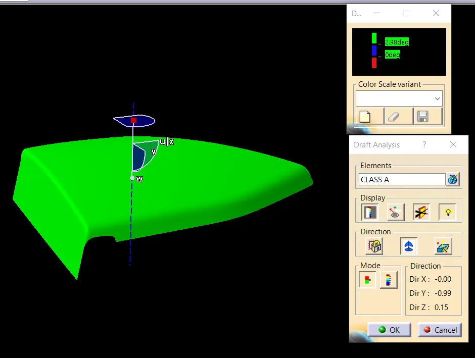
draft analysis for solid part with draft value 3deg
all surfaces are clearing the drafting criteria
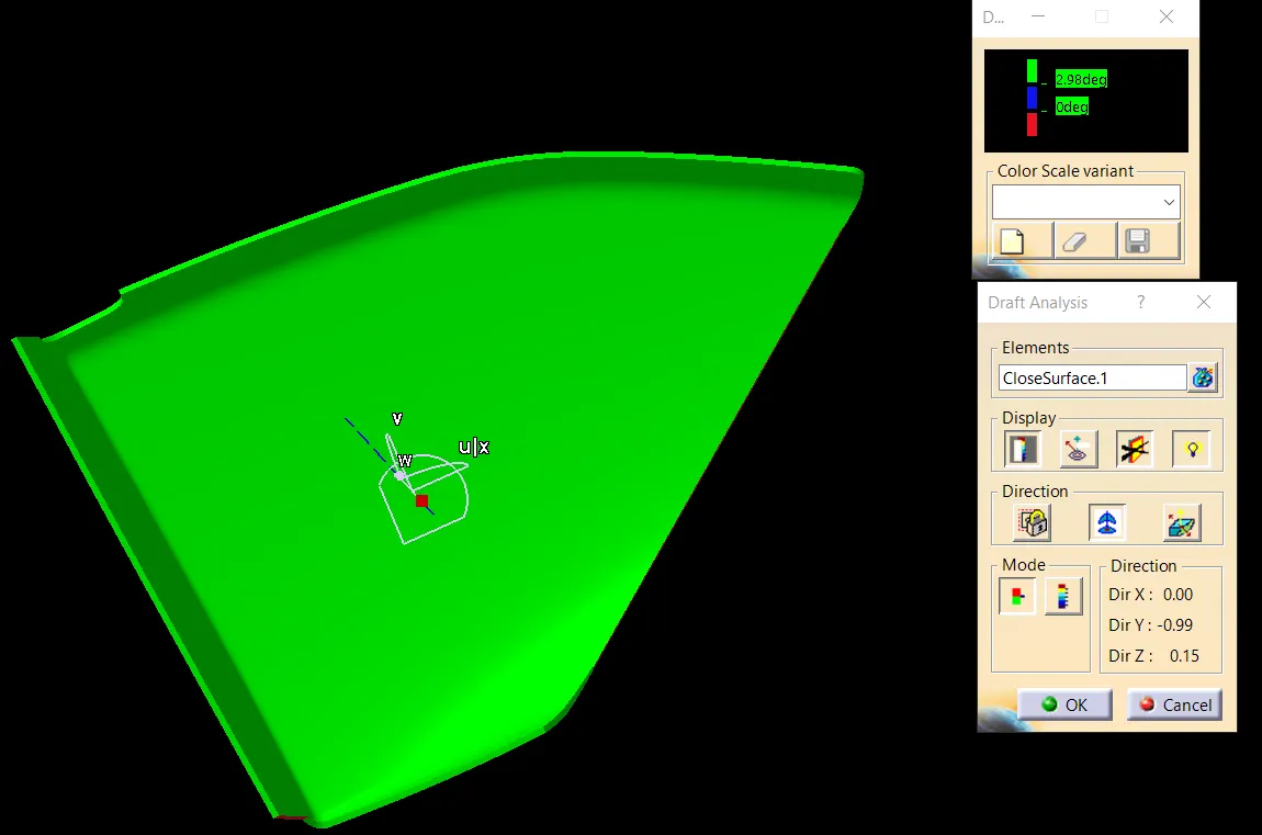
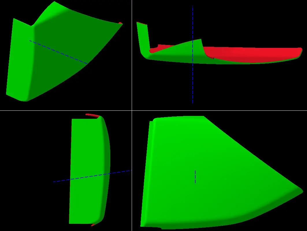
FLANGE DESIGN
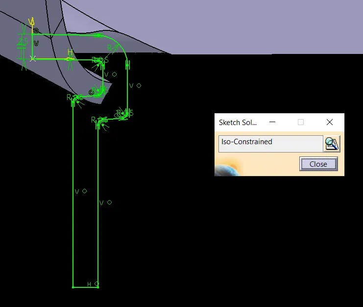
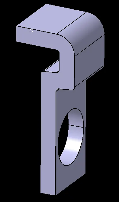
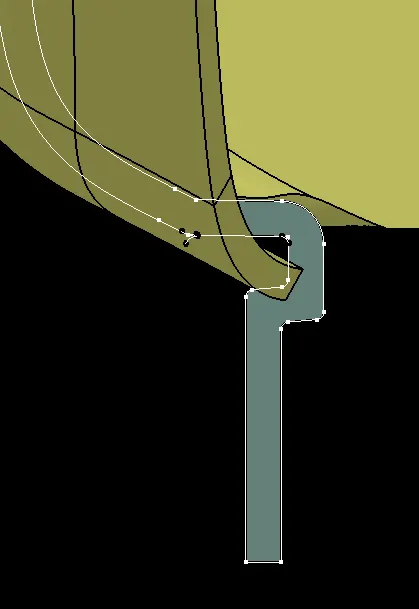
DRAFT ANALYSIS OF SOLID PART WITH FLANGE
WITH DRAFT VALUE 3DEG
DESIGN OF HEAT STAKES
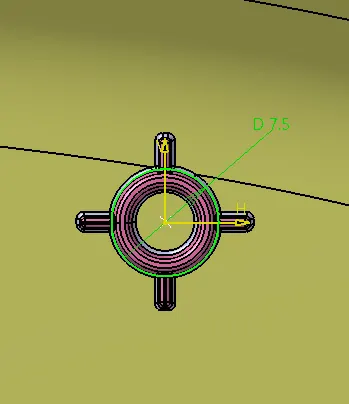
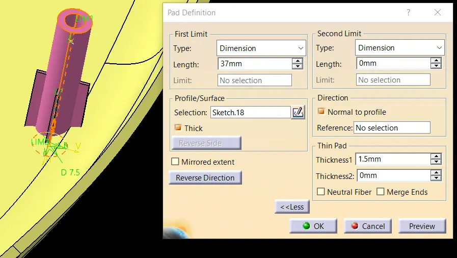
- create a sketch according to the given master section here i create a circle of outer dia 7.5mm
- pad it with thick check box on and give thickness value 1.5mm
- provide draft to inner and outer surface of 0.5deg and select pulling direction as the main tooling axis of map pocket
- give fillet of radius 0.25mm
design of Boss gussets (rib like structure giving strength to the screw boss) must meet ribs guidelines
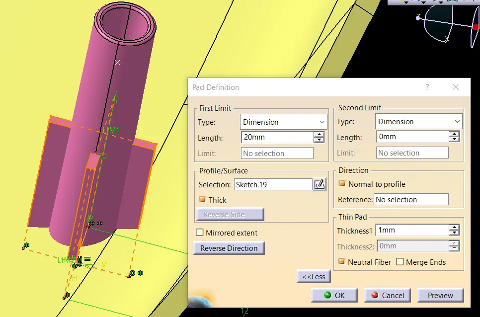
- provide draft of 0.5deg to each wall with pulling direction as main tooling axis of map pocket
- give fillet to edges of radius 0.25mm
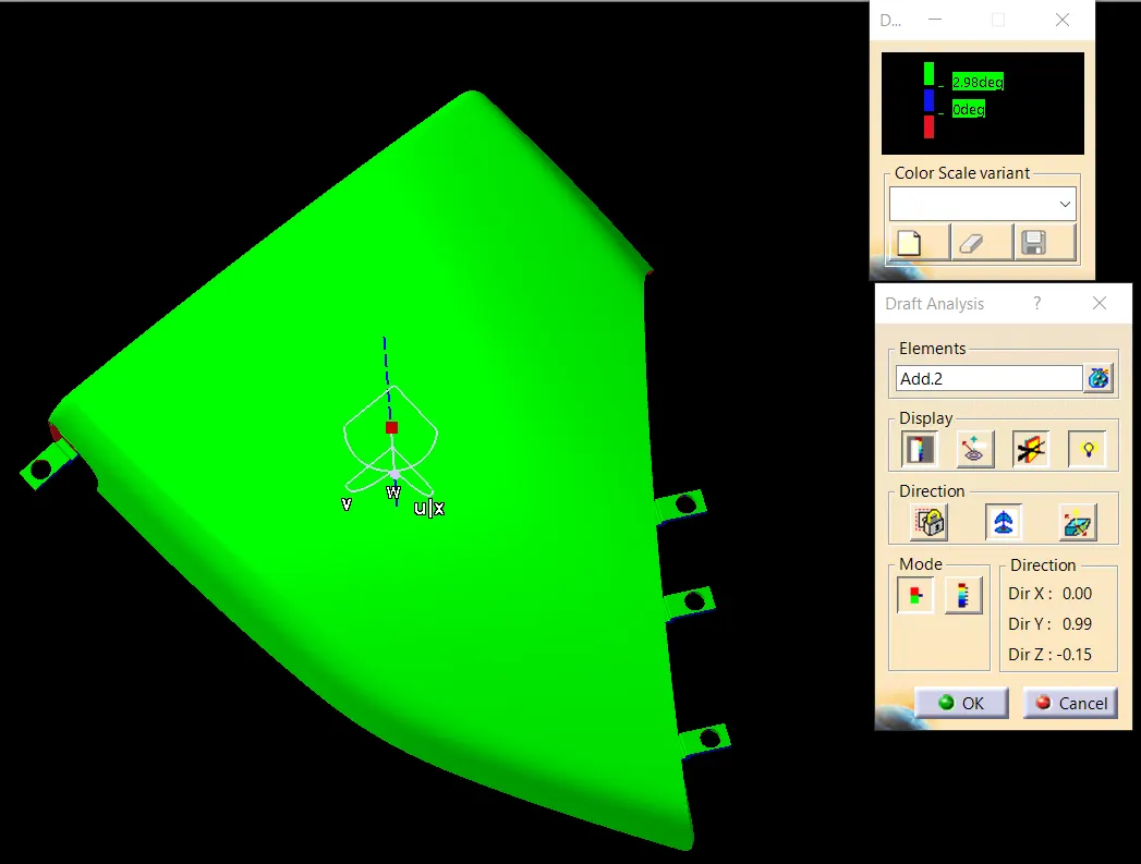
DRAFT ANALYSIS OF FINAL PART WITH HEAT STAKES
FOR DRAFT VALUE 0.48deg with main tooling axis
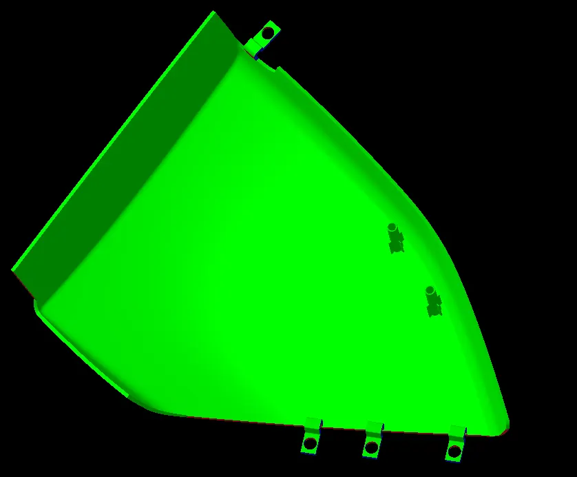
DOOR ARM REST
GIVEN CLASS A SURFACE
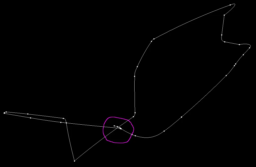
here there is defect in the CLASS A surface so we cannot proceed with the given class A surface
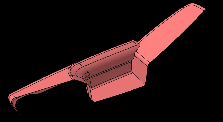
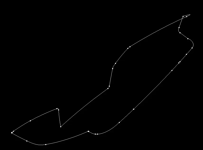
alought we are not allowed as a plastic designer to make any improvements in the class-A surface but for this project correcting the CLASS A surface by using extract,trim join and boundry command
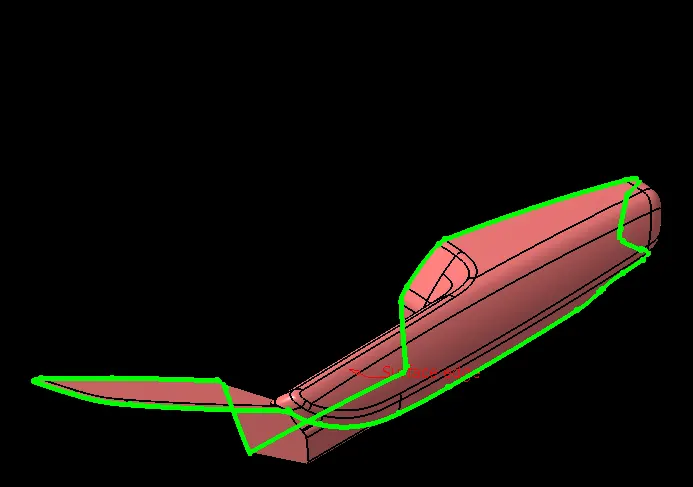
CREATION OF TOOLING AXIS
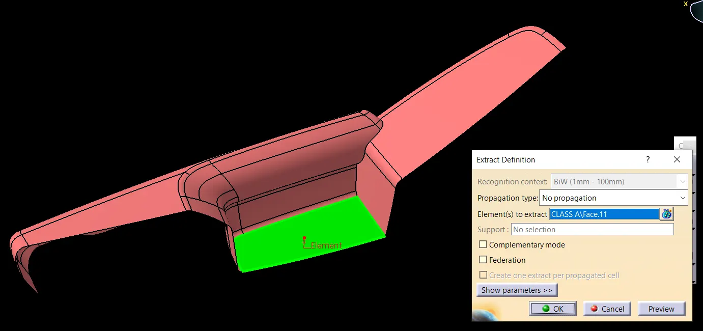
- extract the base surface as shown below
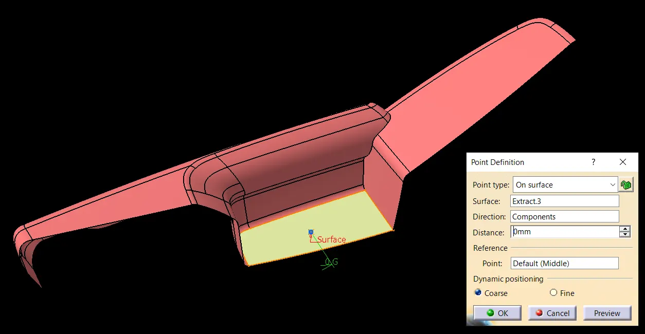
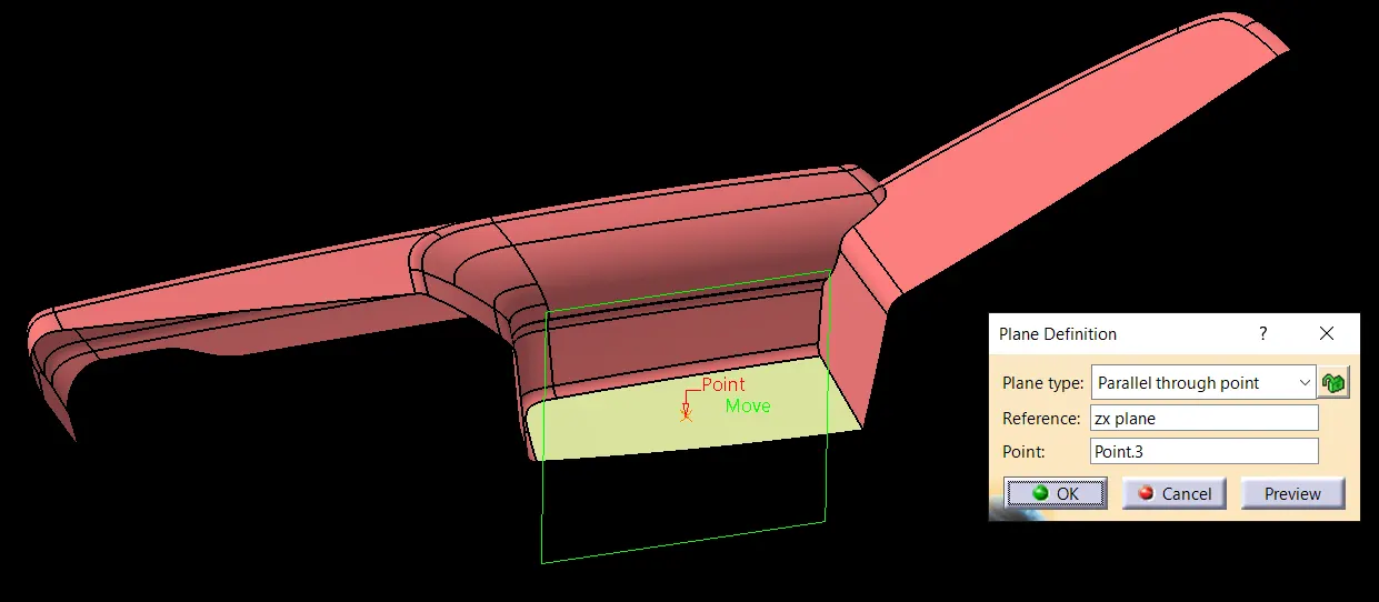
- create a point at center of extracted surface and at that point create ZX plane
- now take intersection between class A and the plane that we created above
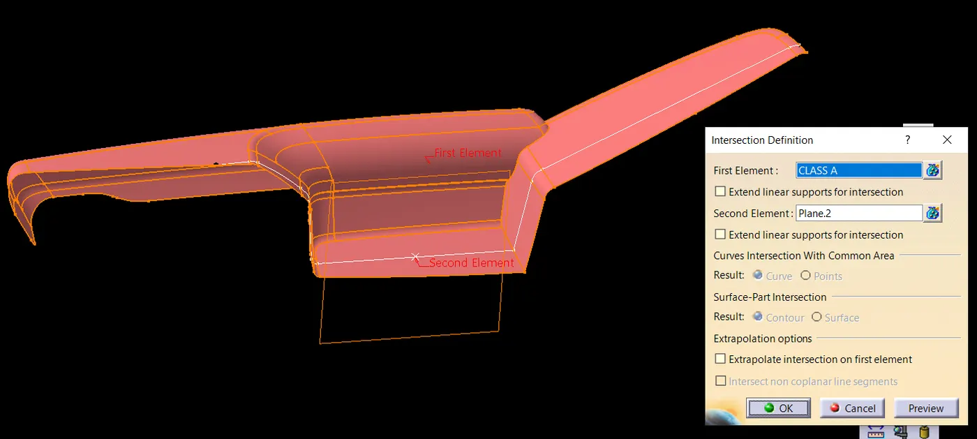
- create 2 lines as shown below with the help of intersection
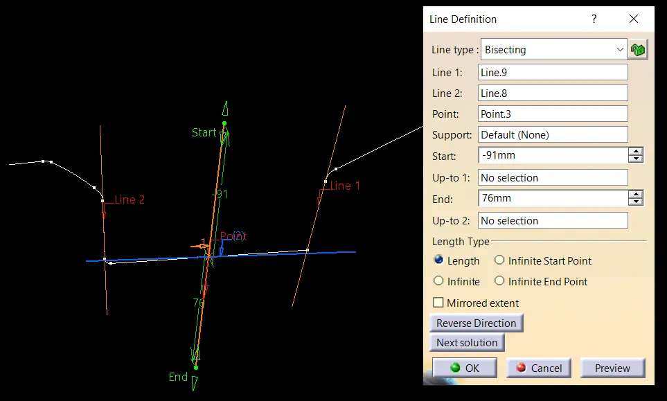
- create a bisecting line where the two lines and point will be selected as inputs.
- now we do draft analysis with above created bisecting line here i slightly inclined the bisecting line in order to minimizing the patches which is not cleared in draft analysis and lock the compass the create a new line at the same position as of inclined line and name this line as main tooling axis
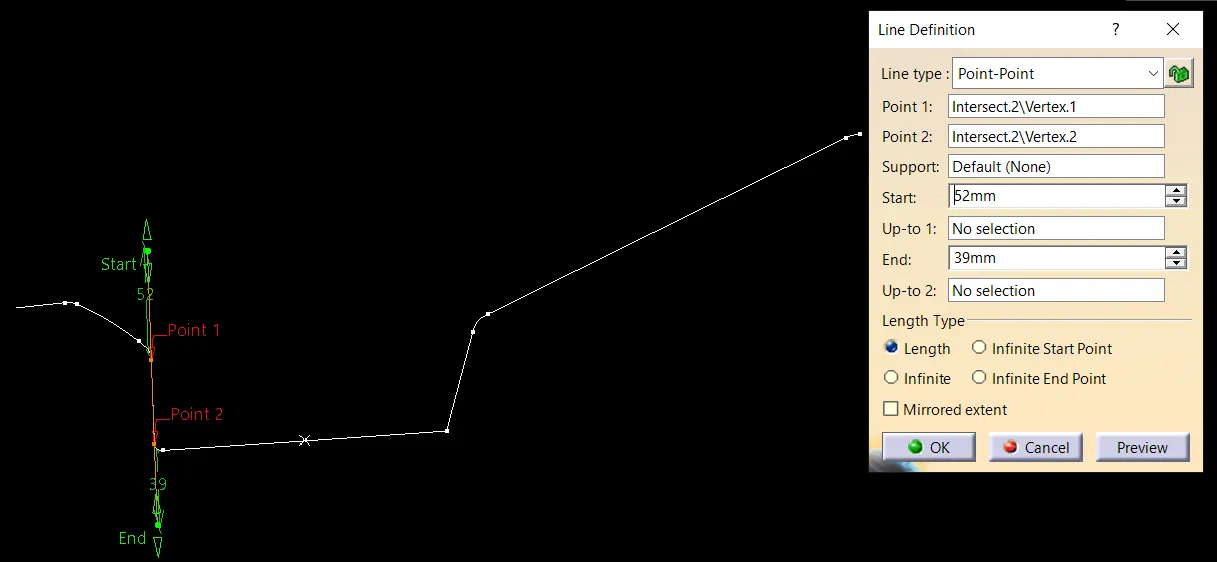
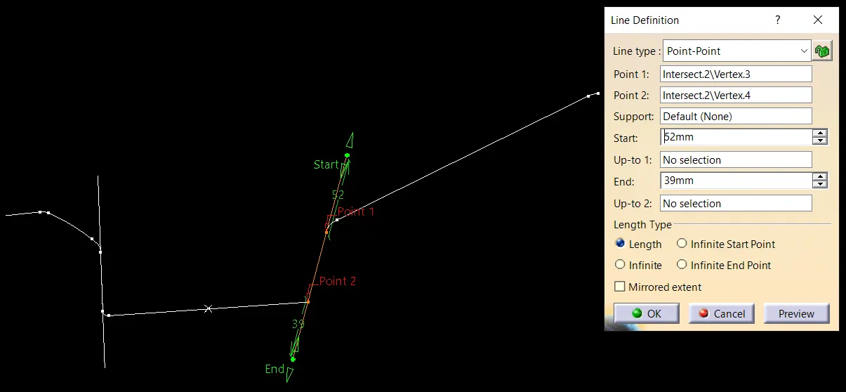
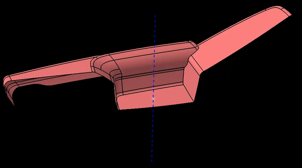
CLASS B SURFACE
To create CLASS B SURFACE take offset of 2.5mm from CLASS A
missing surfaces are created by multi section command
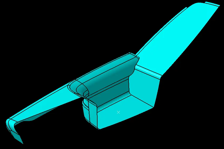
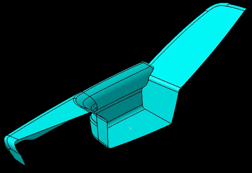
CLASS C SURFACE
Create class C surface with sweep and muti section command
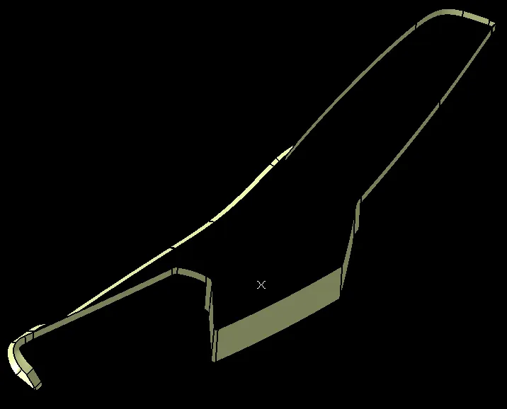
SOLID PART
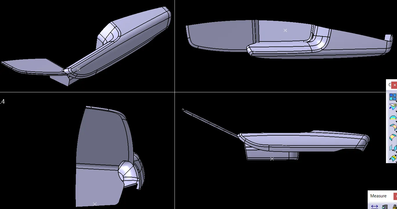
DRAFT ANALYSIS
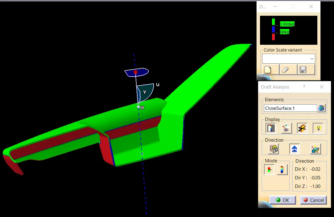
CLASS A SURFACE with draft value 3deg
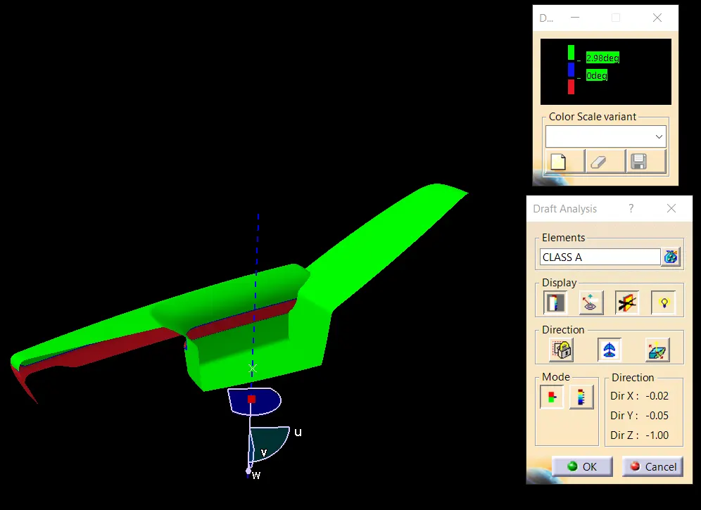
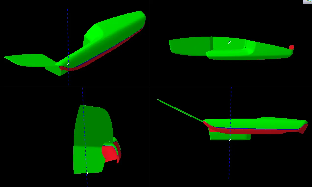
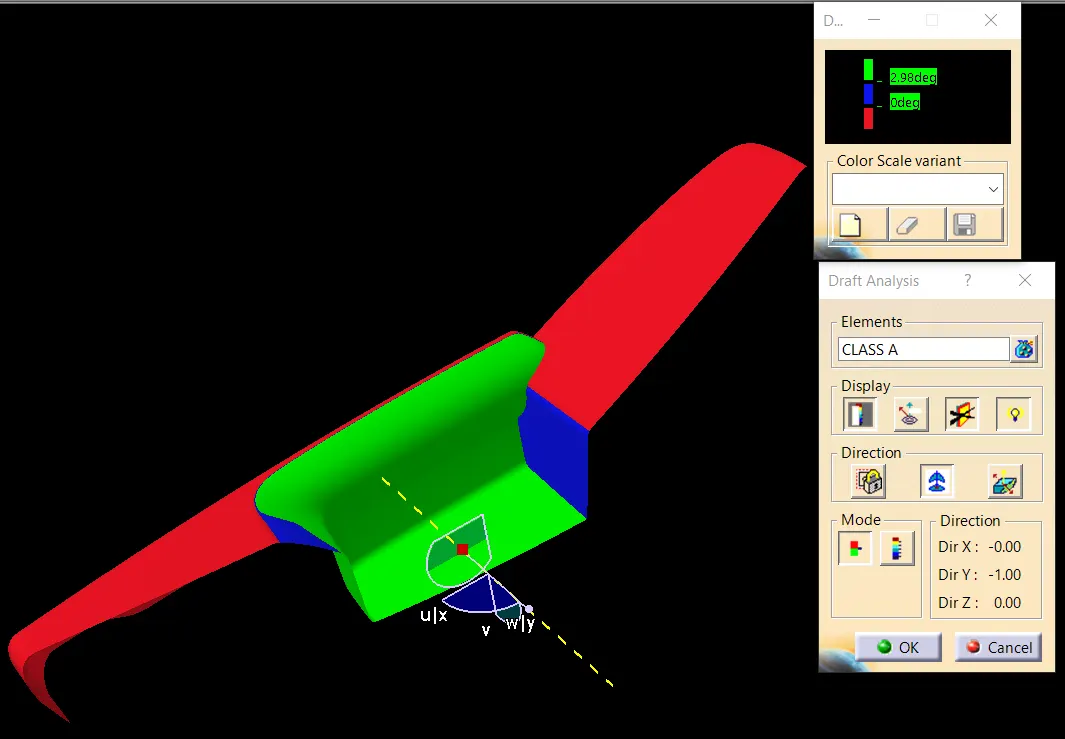
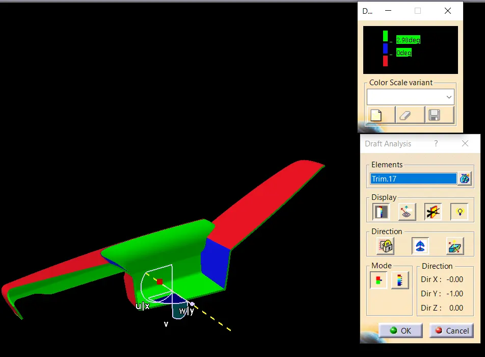
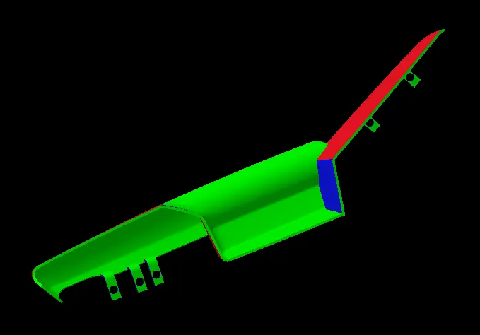
As the entire surface is not getting drafted from a single tooling axis it needs to be draft using a second tooling axis as shown in the image. This results in providing a side core axis that can be used to produce the component and to make sure that it passes the draft criterias.
DRAFT ANALYSIS OF SOLID PART
WITH DRAFT VALUE 3deg
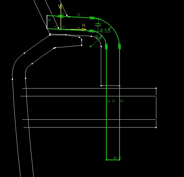
FLANGE
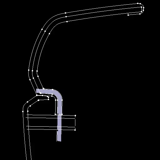
FINAL PART WITH FLANGE
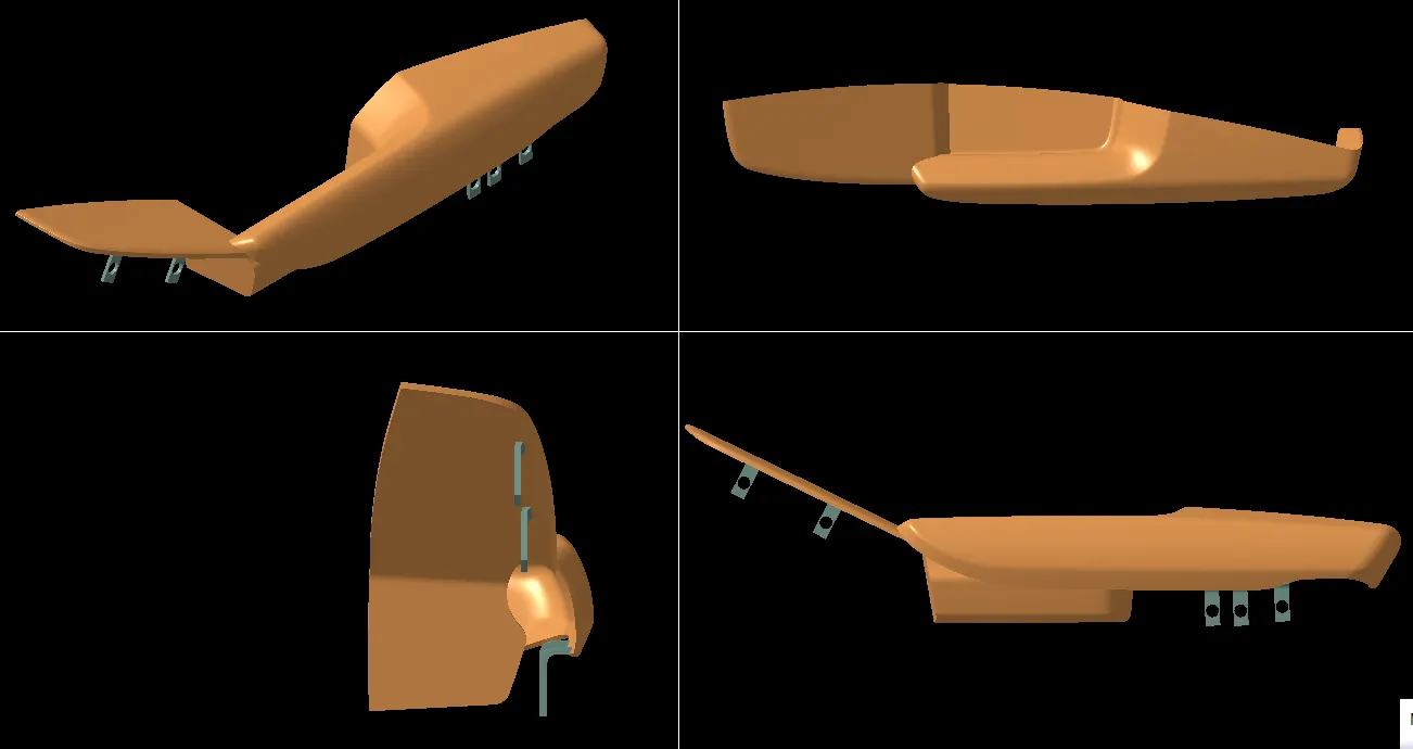
DRAFT ANALYSIS OF FINAL PART WITH SIDE CORE AXIS
FOR DRAFT VALUE 3deg
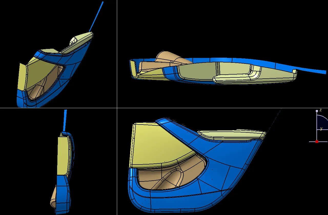
ASSEMBLY
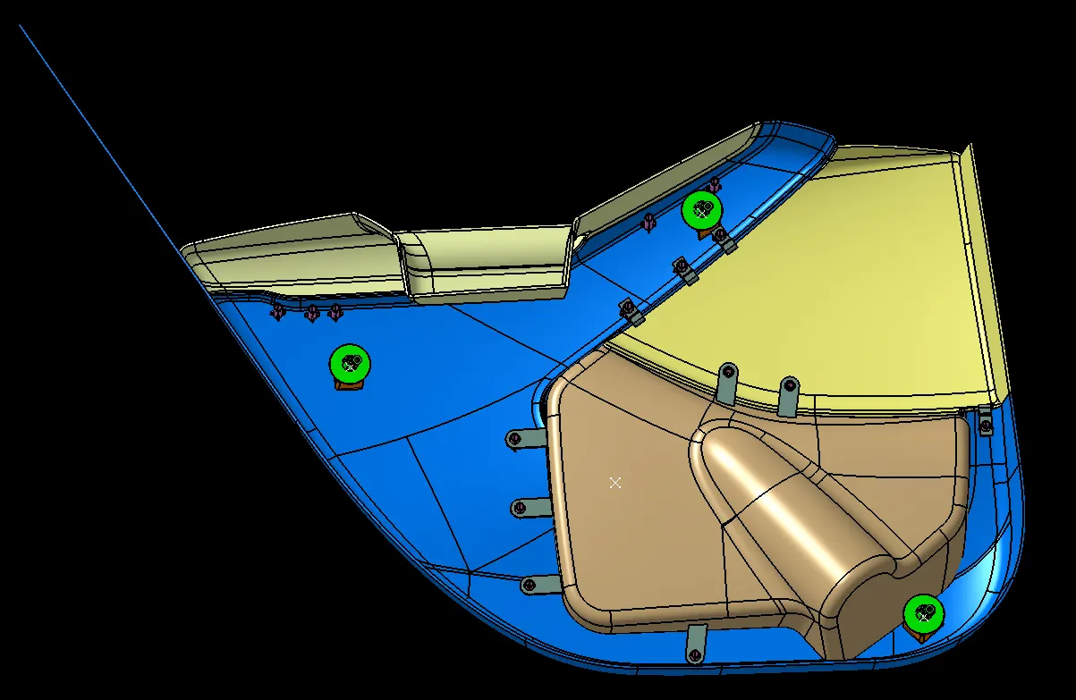
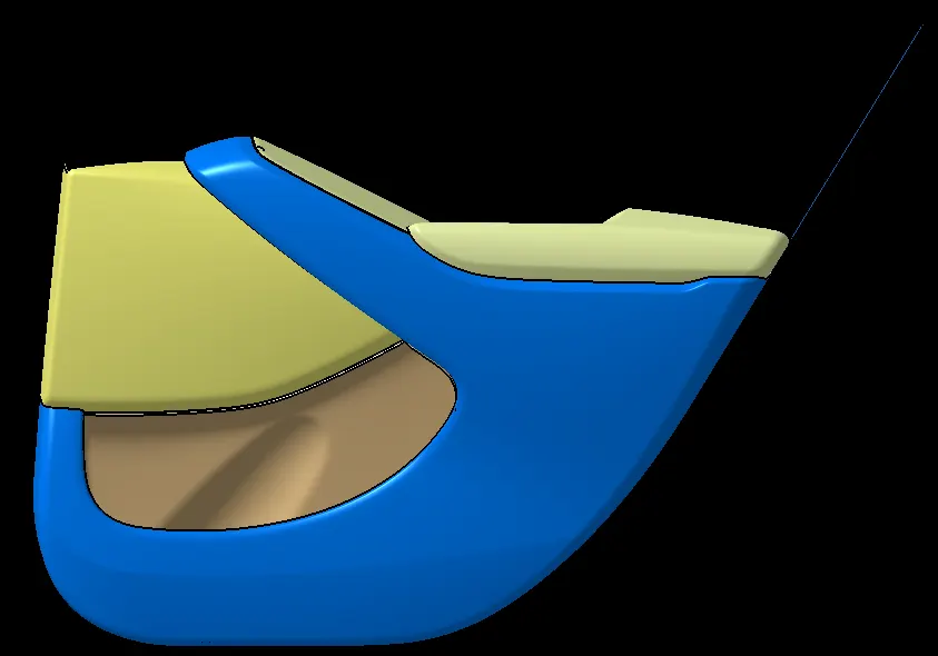
DIFFERENT VIEWS
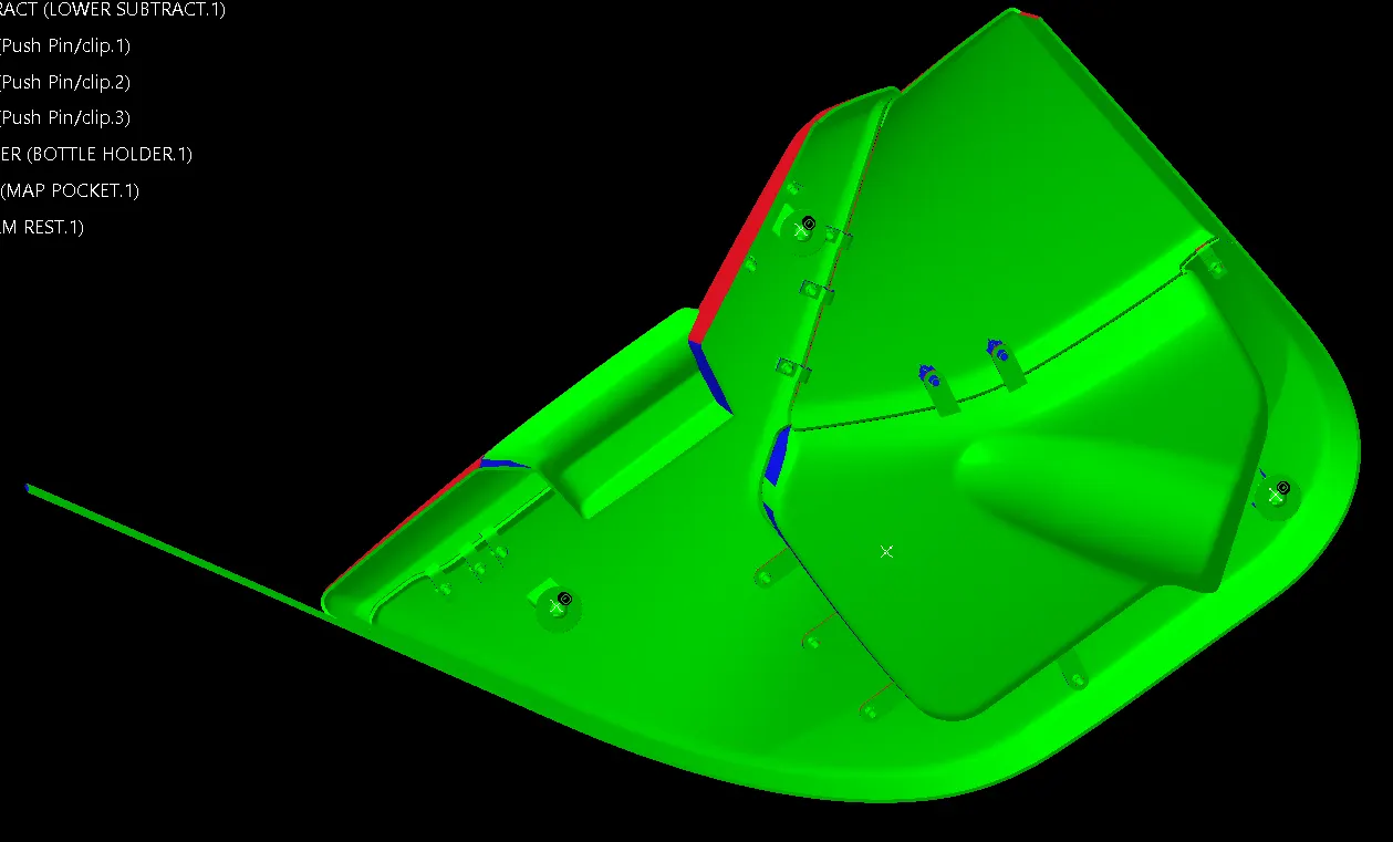
DRAFT ANALYSIS OF FINAL ASSEMBLY
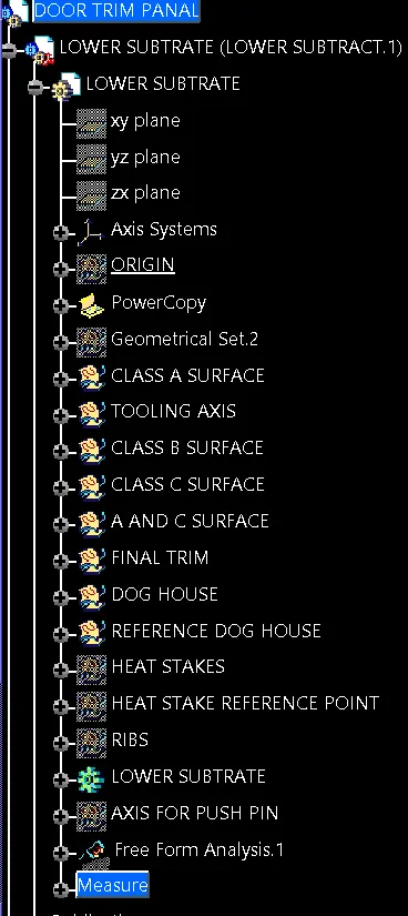
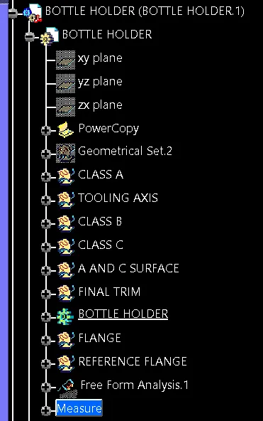
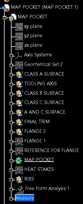
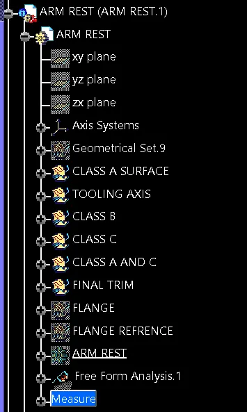
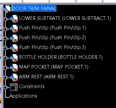
TREE STRUCTURE