Week 12- Final project
FINAL PROJECT
DOOR DRIM ASSEMBLY:
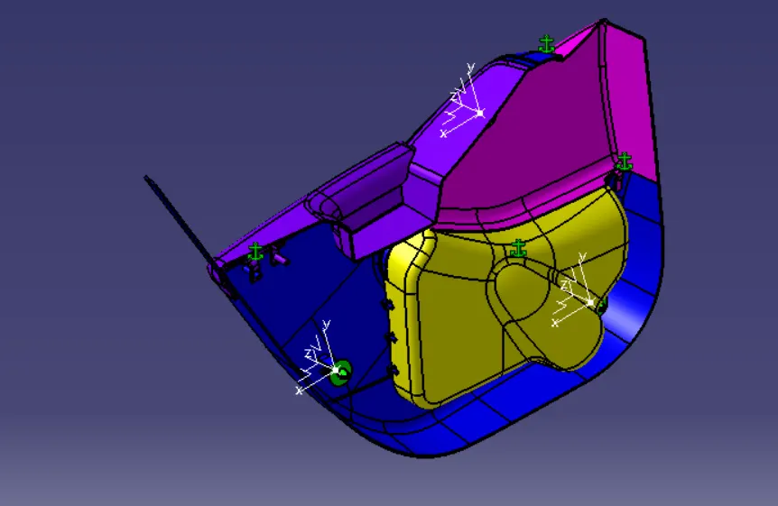
ISOMETRIC VIEW:
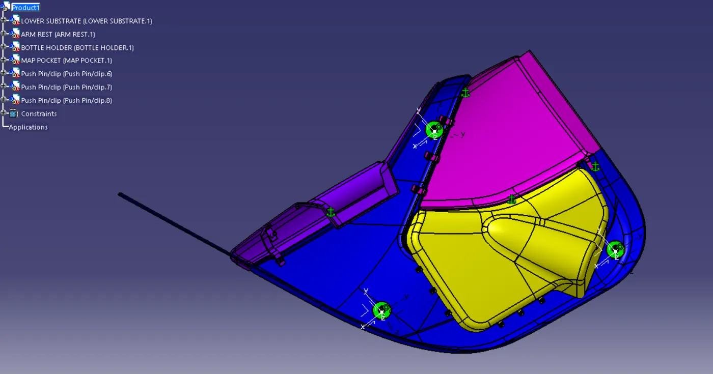
TOP VIEW:
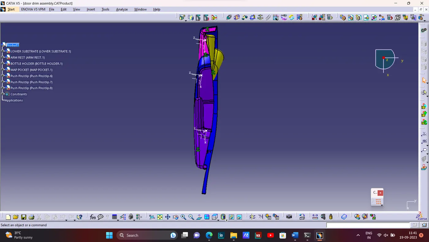
SIDE VIEW:
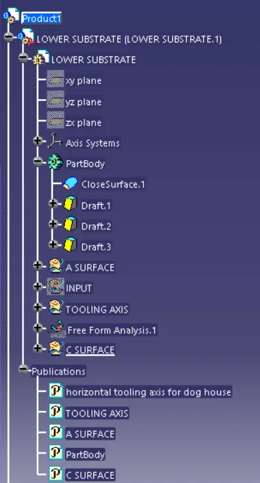
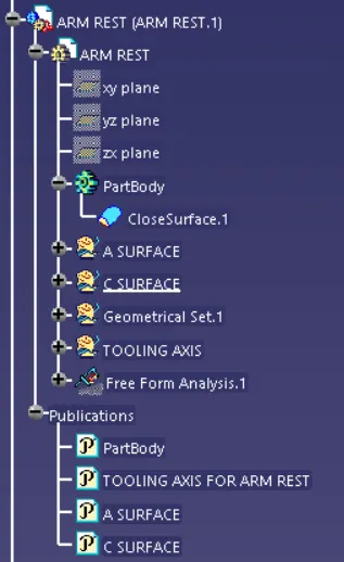
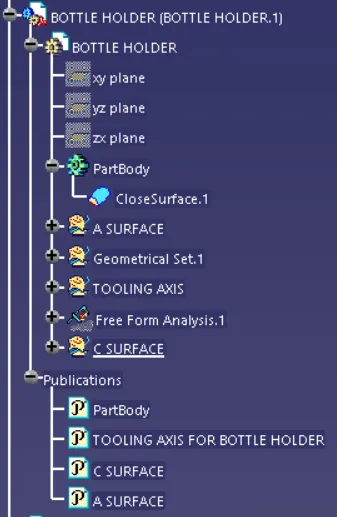
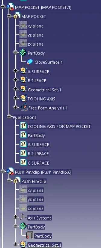
FEATURE TREE:
DETAILED REPORT ON FINAL PROJECT
AIM:
To Create CAD model considering following inputs as like in OEM and tier1 companies
- a) Class A surface
- b) Nominal thickness
- c) Attachment strategy
OBJECTIVES:
Create a sketch by using Positioned sketch
All the sketches should be Iso-Constrained
Ensured Proper feature Tree Structure
Geometrical sets should have a proper name based on the sketches present inside of it
To create thickened part using master section for reference
To create the mounting features as per design guidelines in the industry and with master sections
Creation of Draft analysis & Tooling analysis
Creation of parting lines and check tooling feasibility
SOFTWARE USED:
CATIA V5
INTRODUCTION:
The ten stages in automotive product life cycle development are listed below .
1)Concept sketch
2) Styling class A
3)Feasilbility check
4)Concept validation
5)New product design
6)Product developement
7) Prototyping
8)Design validation
9)Pilot production
10)Mass production
From the above stages , stage 5 (ie).. a new product is designed and validated from class A surface . Then class B and class C surface from given class A surface is developed and a solid body from it formed using software CATIA V5 taking into consideration of the draft analysis which makes the component suitable for production using injection molding process .
The procedures to create a new plastic component from given class A surface are:
1) Creation of tooling axis
2) Creation of class b surface
3) Creation of class C surface
4) Creation of closed body
CREATING THE TOOLING AXIS:
The tooling axis is used to find the direction in which the part is removed from the core and cavity.
The draft angle should be positive to the tooling axis to manufacture the component easily. The step by step procedure of creating the tooling axis is given below.
Bisecting Method in CATIA for Tooling Axis Creation
Step 1: Import the DOOR DRIM component into CATIA.
Step 2: Identify the reference points, reference lines, and reference planes required to define the tooling axis.
Step 3: Create the reference point(s) using the appropriate CATIA tools, such as "Point" or "Datum Point." Ensure that the reference point(s) are placed strategically on the component to establish the desired axis direction.
Step 4: Construct the reference line(s) using the "Line" tool in CATIA. These lines will serve as guides for the tooling axis direction. Align the reference lines according to the design requirements.
Step 5: Generate the reference plane(s) using the "Plane" tool in CATIA. These planes will define the initial orientation of the tooling axis. Ensure that the reference planes align with the reference lines and are appropriately positioned.
Step 6: Utilize the bisecting line concept to establish the final tooling axis direction. Identify the two reference lines that define the desired axis direction. Construct a bisecting line between these reference lines using the "Bisecting Line" or "Line Bisector" tool in CATIA.
Step 7: Validate and define the tooling axig axis and perform draft analysis.
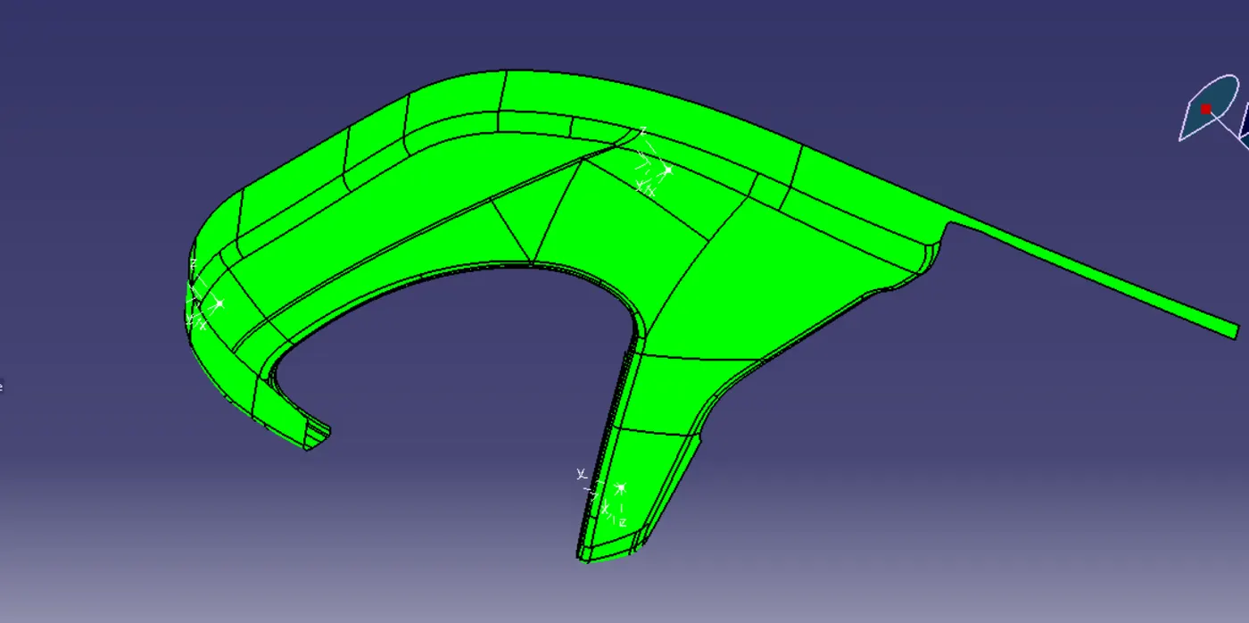
Draft Analysis .
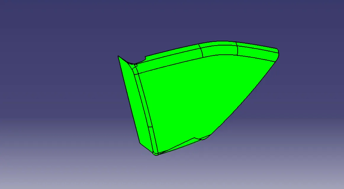
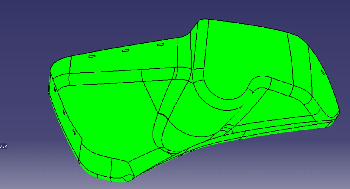
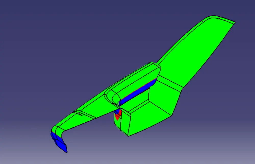
Draft analysis is done to ensure that the designed part is manufacturable based on the draft conditions applied. It is done to ensure the proper ejection of the component from molds .The basic idea is to ensure that the tooling axis has to be created in such a way that it has no parallel surface profiles of the component so that the ejection of the components can be ensured . Tooling axis is the axis along which cavity and core are closed and opened .
The main components of interior door panel of a car consists of the following parts .
DRAFT ANALYSIS ON LOWER SUBSTRATE CLASS A SURFACE:
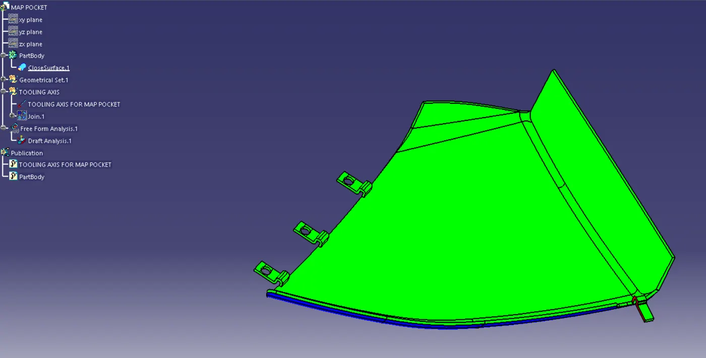
DRAFT ANALYSIS ON MAP POCKET:
DRAFT ANALYSIS ON BOTTLE HOLDER:
DRAFT ANALYSIS ON ARM REST:
CREATING THE B SURFACE:
The B Surface is created by using OFFSET SURFACE COMMAND from given A Surface. The nominal distance from A Surface to B Surface is 2.5mm.
CREATION OF C SURFACE:
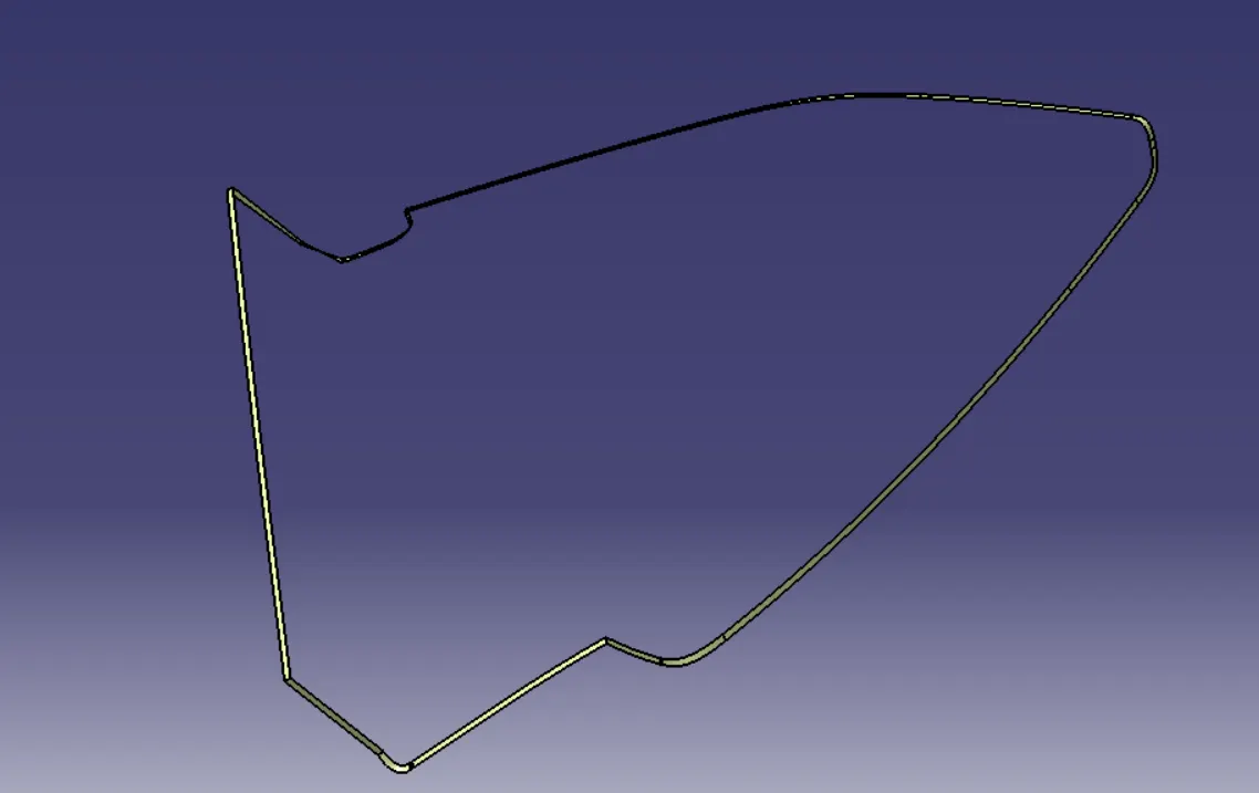
Procedure for creation of class C surface for Upper map pocket
Step 1: Use sweep command to create a new surface an angle with respect to a surface. This angle is dependent on draft angle for free edges and usually 90 degrees for mating surfaces.
Step 2: In areas where sweep is not possible, use Multi section surface to create a new surface.
Step 3: Join all surfaces to obtain C surface.
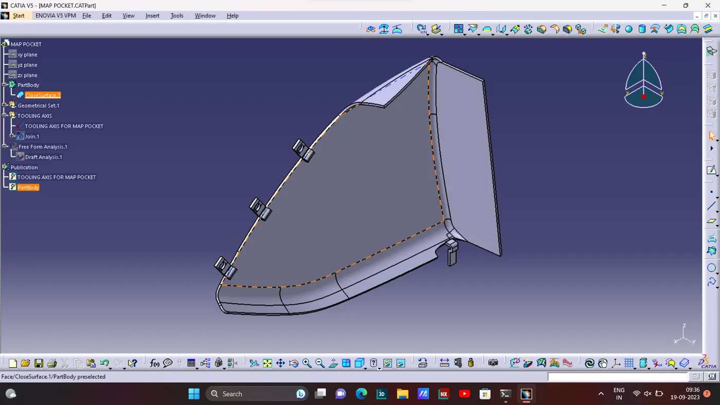
MAP POCKET:
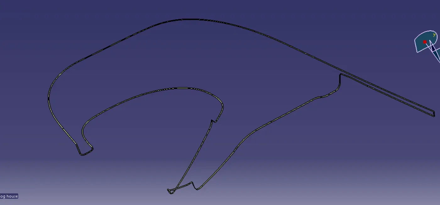
LOWER SUBSTRATE
:
ARM REST:
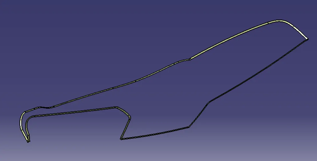
BOTTLE HOLDER:
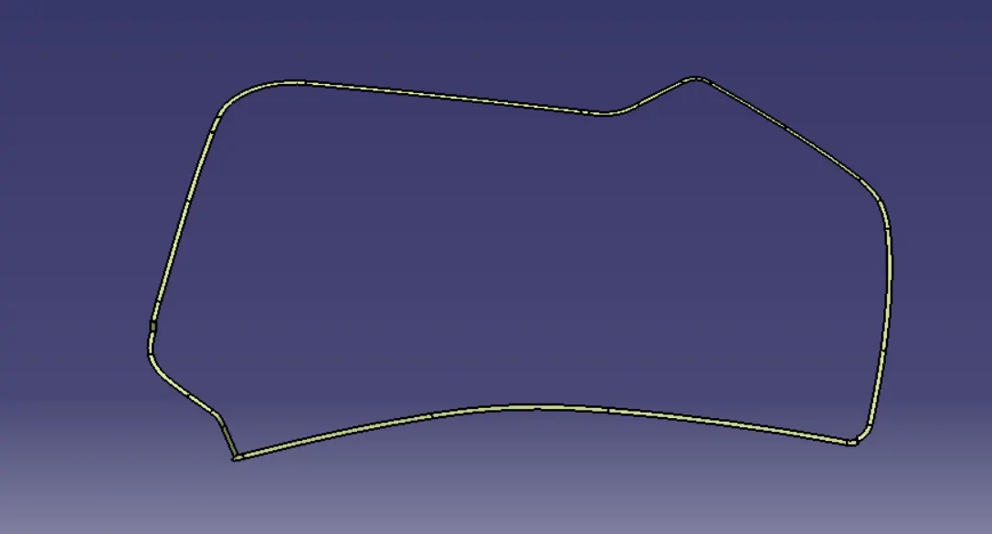
MAP POCKET FINAL BODY:
LOWER SUBSTRATE FINAL BODY:
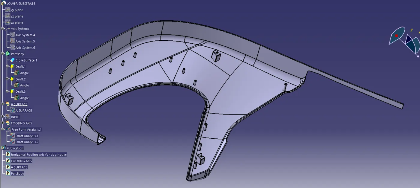
BOTTLE HOLDER FINAL BODY:
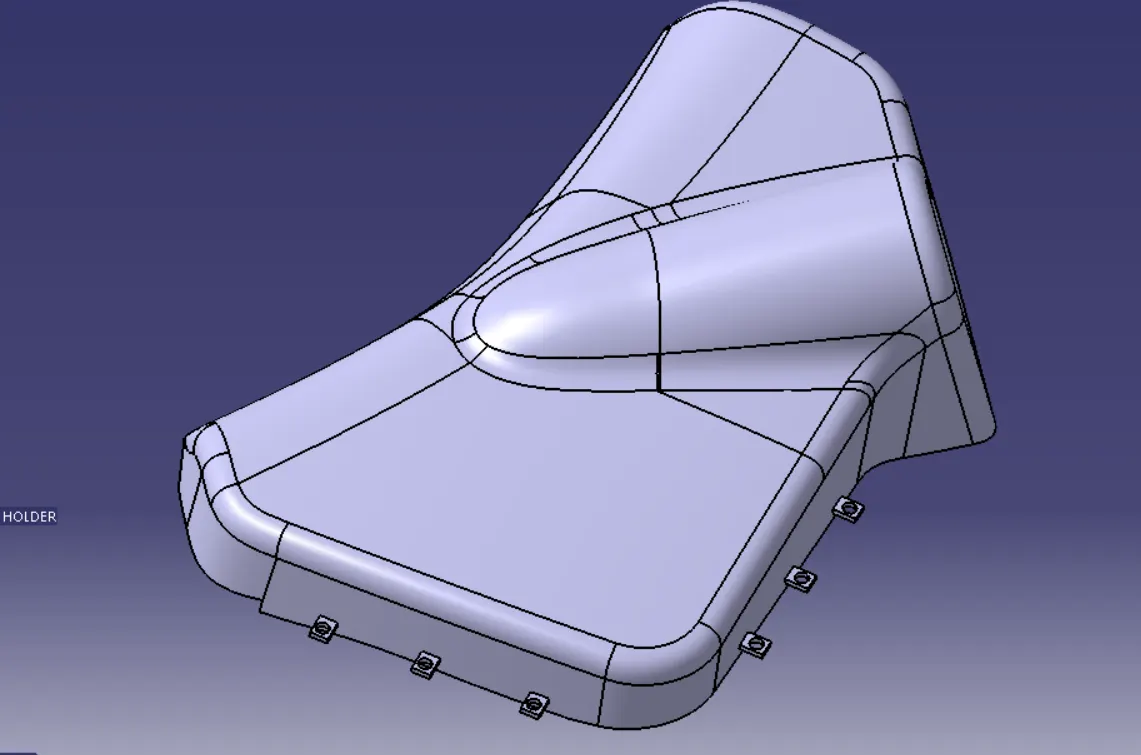
ARM REST FINAL BODY:
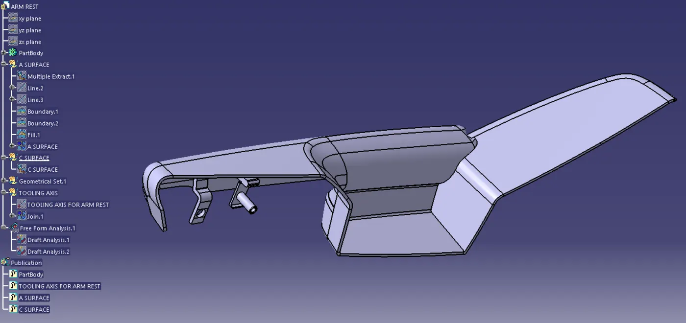
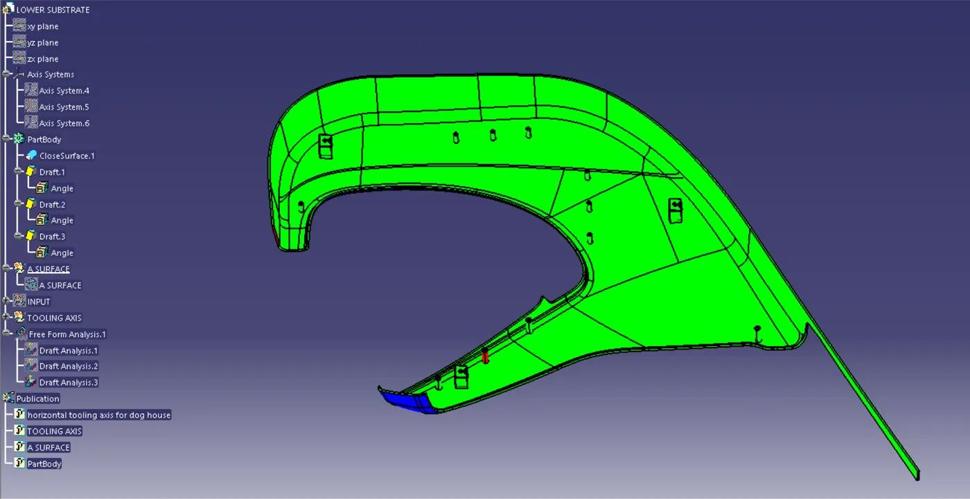
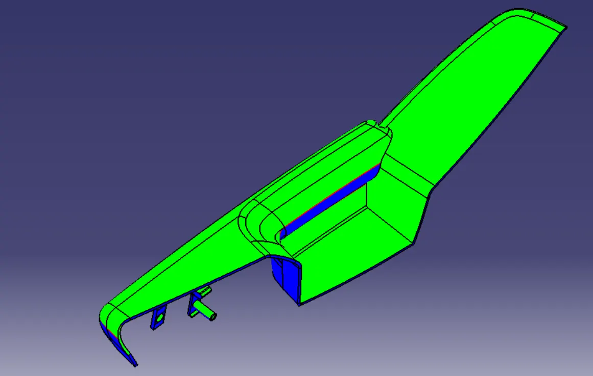
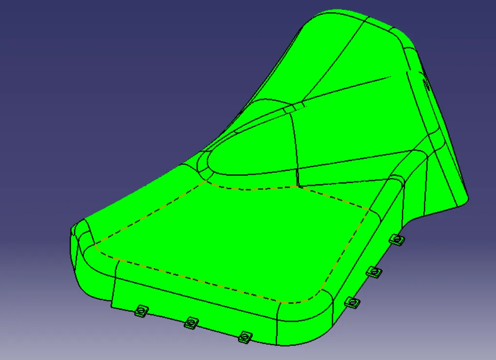
DRAFT ANALYSIS ON FINAL BODY:
MAP POCKET:
LOWER SUBSTRATE:
ARM REST:
BOTTLE HOLDER:
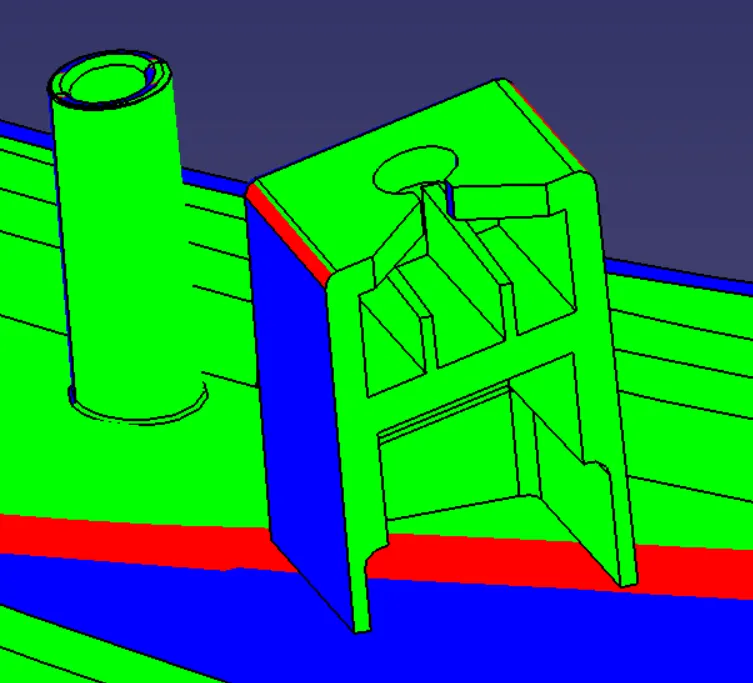
DRAFT ANALYSIS ON DOG HOUSE SIDE TOOLING AXIS:
FINAL ASSEMBLY PART OF DOOR DRIM:
CONCLUTION:
Thus, the CAD model considering following inputs as like in OEM and tier1 companies is created.