Week 12- Final project
Week 12- Final project
DESIGN & DEVELOPMENT OF A CAR INTERIOR DOOR TRIM
AIM ...
The project report deals with the explanation of steps and procedure followed while developing the Door Trim Panel of a car using CATIA V5. Using the CLASS-A surface and master sections as input, we were able to create a Tooling axis, CLASS-B surface, CLASS-C surface, Flanges and form a solid body after which the attachment features such as Dog House, Push Pins, Heat stakes, etc are created. To check the manufacturability of the parts, a Draft Analysis has also been performed using the main/side tooling axis on various components such as
- Straight Arm Rest
- Inclined Arm Rest
- Upper Map
- Lower Map Pocket
- Lower Substrate
OUTPUT...
- CLASS-A surface extraction
- Creation of different Geometrical sets for each component such as lower substrate, map pocket (upper & lower part), armrest (upper & lower part), etc.
- Tooling Axis / Side Core Axis Creation
- Creation of Flanges
- Creation of CLASS-B Surface
- Creation of CLASS-C Surface
- Joining of CLASS-A, B & C Surface
- Performing a check for boundaries
- Forming a Solid Body from closed surface
- Attachment features creation
- Performing Draft Analysis
THEORY...
- Car Door Panel :
Door panels serve as an interface between the interior of the car and the inner workings of the door, and between vehicle occupants and the door. They are expected to meet a variety of design specifications regarding safety, aesthetics, and functionality. In addition, they are expected to continue the material theme of the dashboard and pillars while concealing intricate electrical and mechanical components for operating locks, windows, and other features.
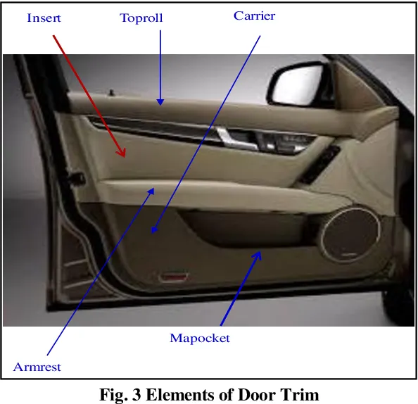
MY DESIGN TREE STRUCTURE
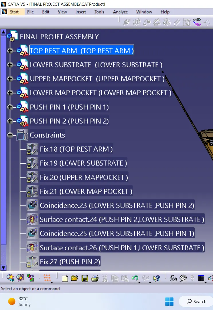
Design of Interior Door trim:
Interior Door trim consists of 4 Major components namely
1)Lower Substrate
2)Upper Substrate
3)Map Pocket
4)Door Arm Rest
| CONSTRUCTION OF TOOLING AXIS : |
Tooling axis :
Tooling direction is basically the direction that mold pulls apart. The mold is built in two seperate pieces, basically you have a cavity side and you have core side, The core pulls apart from the cavity and that's the Tooling direction. While creating a Tooling direction make sure that waterver that is created that is going to be used as a reference to design it may also include Ribs, Pockets, Walls Bosses etc. All are going to be drafted with respect to Tooling axis to make sure that the core can pull apart from the cavity nice and clean.
DOOR ARM REST
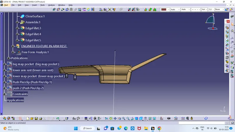
LOWER SUBSTRATE
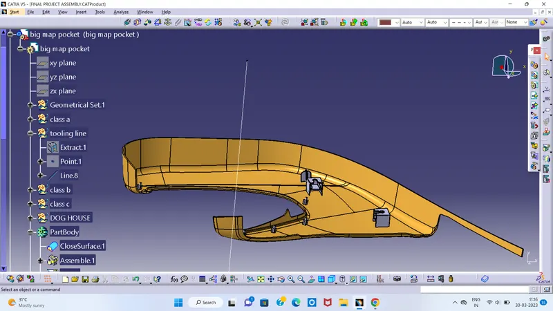
UPPER MAP POCKET
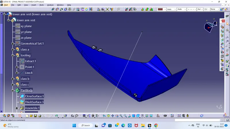
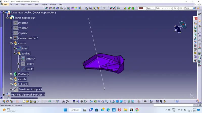
LOWER MAP POCKET
- Draft Analysis
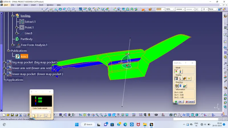
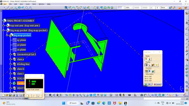
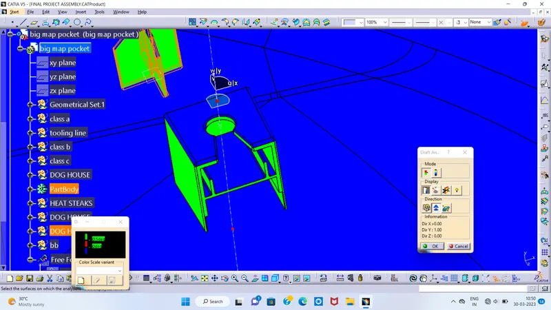
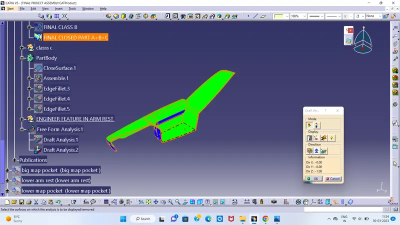
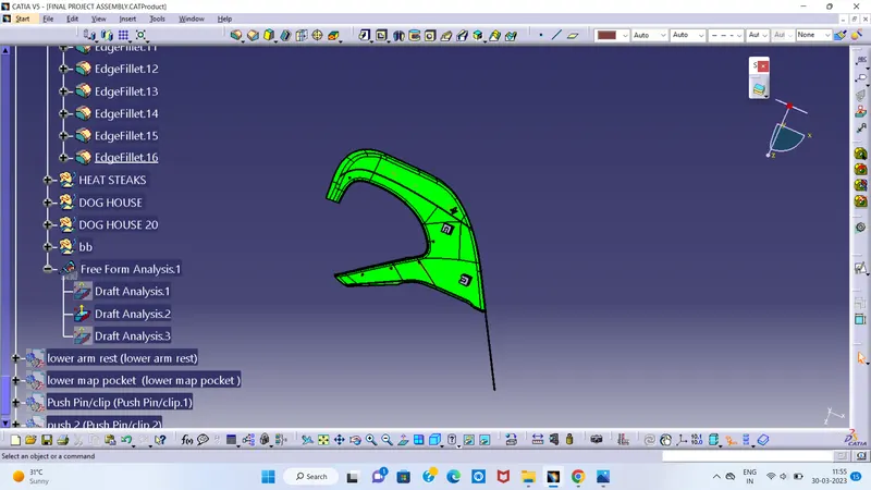
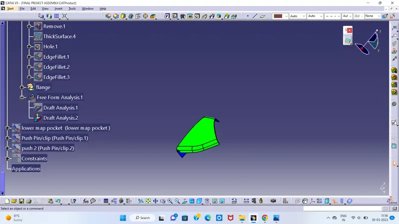
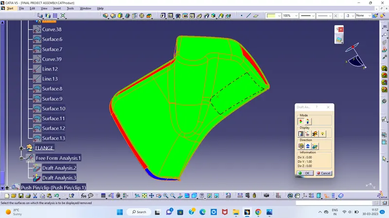
Parts Cannot be ejected from the tool if it is at 90 degree surface.for the reason,A small Draft angle is to be provide for each and every surface s of the Component in order to easy removal of component from the moulds without any defects.Draft is the angle in which the part is tapered to aloow it to release.Most of the part require minimum 1/2 degree to 1 degree however 3 degrees are wudely accepeted in plastic component design.Draft Analysis is the technique used to analise weather our designed product are manufacturable with required conditions or not.
DOOR ARM REST
LOWER SUBSTRATE
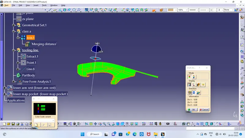
UPPER MAP POCKET
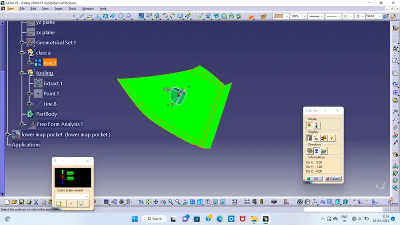
LOWER MAP POCKET
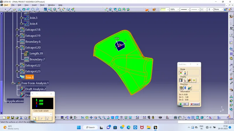
| CREATING B SURFACE |
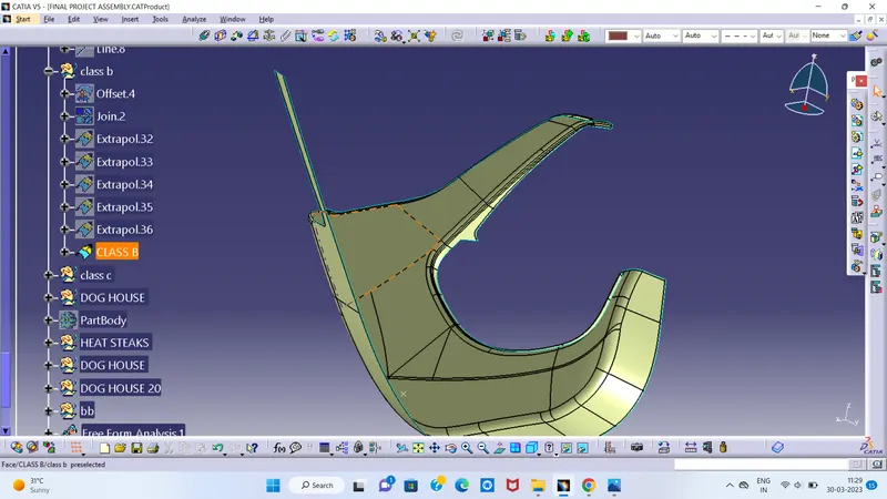
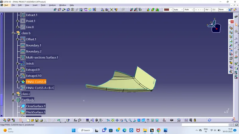
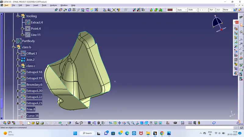
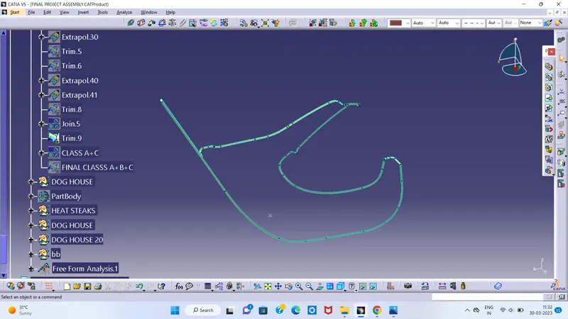
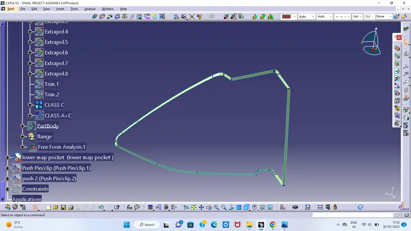
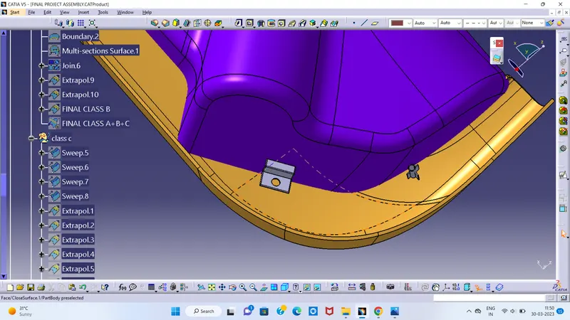
Class B surfaces are the secondary surfaces that you may see sometimes or may not, but are less important. These must be smooth and "error-free" as well, but are not held to the standards that class A surfaces are. After creating the Tooling axis, B surface is to be created which is nothing but the surface parellel to the A surface. B surface contain all the fillets and the edges which the A surface containsDepending on the geometry, the extraction and offset of the fillets might generate non-uniform thickness. So it is advisable to extract only the flat surfaces and then apply fillets at the end of Class B formation.
lets start the process of creating class B by choosing the respective A surface and extract with no propagation option then untrim the extracted surface to get the basic geometry.after getting the original/basic surface the surfaces have to overlap each other in order to facilitate trimming therefore extrapolate it up to the required dimension.then we finally trim them.
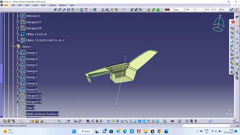
| CREATING C SURFACE |
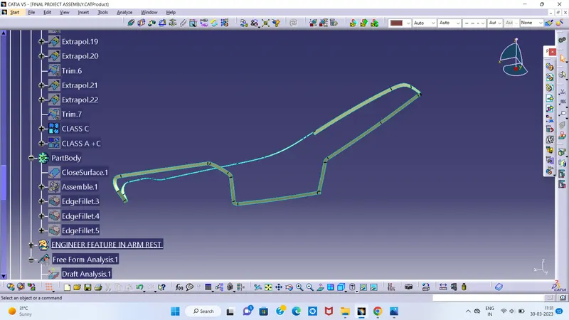
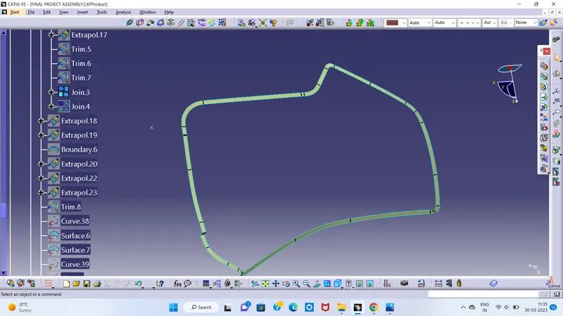
C surface is the part of the geometry that connects Class A with B surface.Rules to be followed for C surface creation is A minimum draft of 3 degrees should be provided to facilitate the Ejection of the Molded component.The parting line should be on the B surface. This means that the draft should sweep outwards, from the C surface
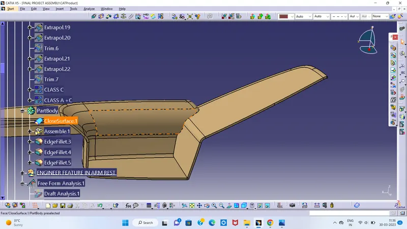
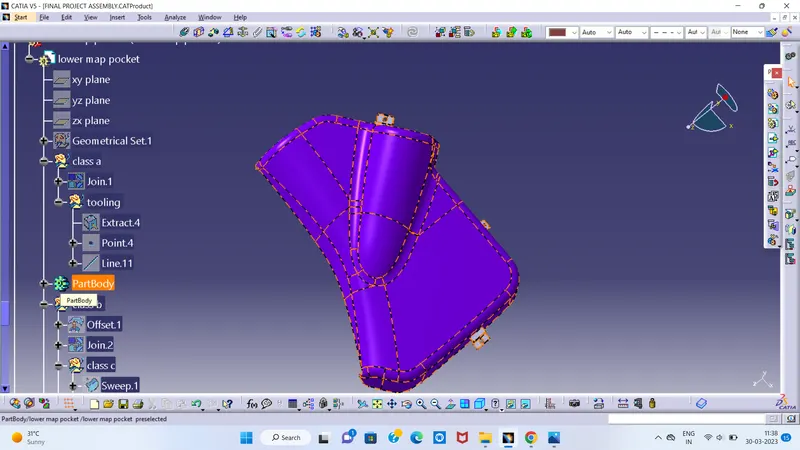
- Making closed solid bodies from joined surfaces
DOOR ARM REST
LOWER SUBSTRATE
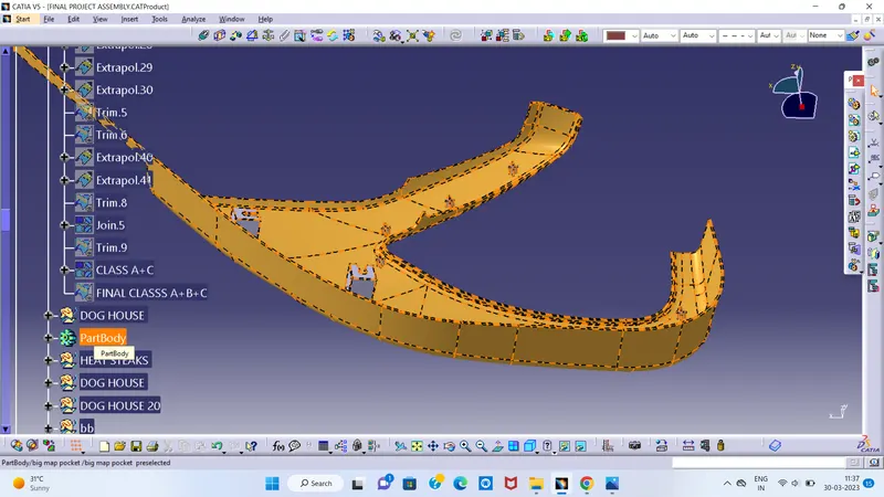
UPPER MAP POCKET
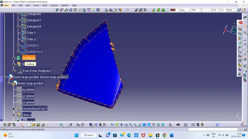
LOWER MAP POCKET
|
CREATING ENGINEERING FEATIRES
|
DOG HOUSE :
Dog house is an engineering feature used in plastic trim design. Dog houses are used as supporting feature. Sometimes other engineering features like snaps; locators etc. are mounded on them to increase their strength.
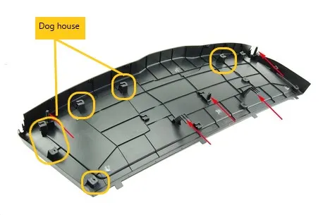
Dog houses are subjected to draft analysis to prevent breakage of the component during ejection from mould cavity. Dog house and other engineering components are built on B-surface.now we will proceed with creating a dog house and mount the boss on it by following the design rules mentioned below..
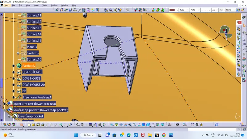
CHECKING DRAFT ANALYSIS FOR DOG HOUSE
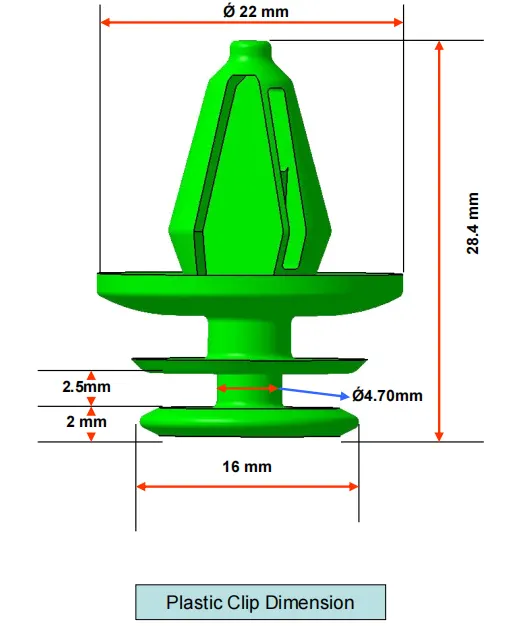
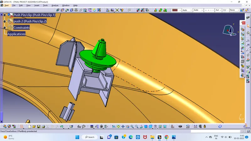
PUSH PIN :
Pushpin which helps us in Locating and Arresting components of an Assembly and it provides Alignment in Mating Parts and it also acts as a stopper or guide for various mechanisms.
DESIGN GUIDELINES FOR PUSH PIN
HEAT STAKE :
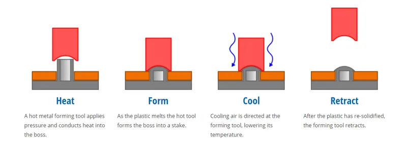
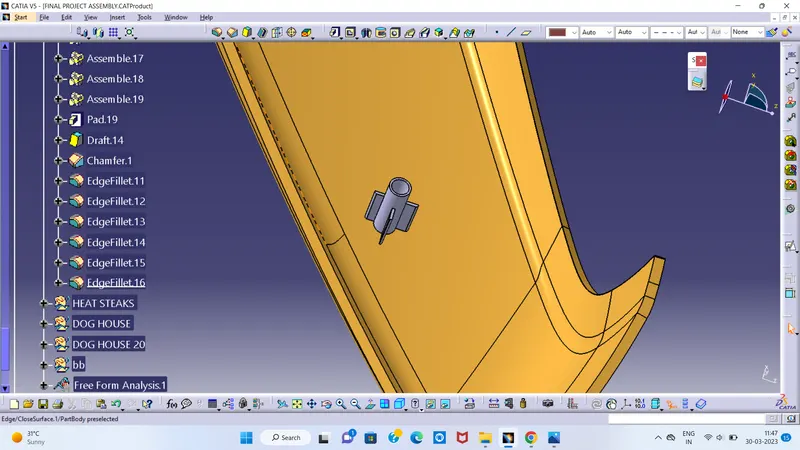
- Heat stakes :
In manufacturing products with thermoplastic components, it is often necessary to join a thermoplastic to a part of dissimilar material, whether it be metal, a dissimilar plastic, or other material. This technical information sheet provides design guidelines, configurations, and techniques for successful thermal (heat) staking.
Holes on flanges for fixation :
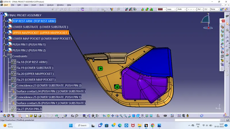
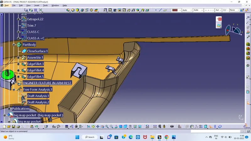
The door trim Assembly has to be rigidly fixed as one unit.The 4 components will be permanently arrested to the Lowered substrate by using the Heastakes.The Heatstakes will pass through the flanges of the components, therefore some clearance of 0.1mm has to be provided.
| FINAL DRAFT ANALYSIS |
In the injection molding process, plastic products are difficult to demold due to friction force between the cavity and products, thus, finished products might be deformed or damaged. Therefore, designers should add a draft angle to the geometric surface of products, which is parallel to the unloading direction, in order to help the products eject smoothly from the cavity. This study uses CAD software as the main architecture to develop the function of automatic draft angle recognition and construction. The study is divided into three stages. First, the geometric features of products are identified in the CAD model by induced algorithm, then the quilts to be added in the draft design are determined and classified. Finally, draft angles are created in different ways according to different surfaces
| BOTTOM-UP ASSEMBLY |
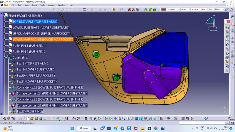
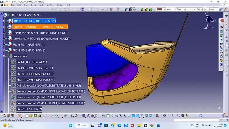
The components are created in separate part files and are then inserted into the assembly file. They are assembled at their working position by applying assembly constraints to them. To create an assembly using this approach, it is recommended to insert the first component and fix its position after properly orienting it in the 3D space. The other components can be inserted and positioned with reference to the first component.
| RESULT |
Finally,the Interior trim of the Car interior door trim is designed using the given A Class Surface as the Input and B and C Class Surfaces are created with respect to the A Class Surface for the components listed down below
1)Lower Substrate
2)Upper Substrate
3)Map Pocket
4)Door Arm Rest