Week 12- Final project
AIM:
To develop the Door Trim panel
OBJECTIVE:
- Creation of CAD model considering following inputs as like in OEM and tier1 companies
- a) Class A surface
- b) Nominal thickness : Refer master sections
- c) Attachment strategy :
- Find a attachment strategy for the door panel complete work.
- Use Push pin with Dog house for Lower substrate – Door panel attachment
- Use heat stakes for part to part attachment
Output required:
- Create thickened part using master section for reference
- Create the mounting features as per design guidelines in the industry and with master sections
- Apply material details :
- Draft analysis & Tooling analysis
- Creation of parting lines and check tooling feasibility
SOFTWARE USED : CATIA
Let us look at how we have designed
INPUT:
CAD DATA is downloaded and Opened with CATIA.
TOOLING AXIS:
Tooling axis is defined as such all the features of the part can be manufactured easily. so here we followed the below steps to create the tooling axis.
- Tooling Axis created for the parts.
- Different ways of tooling axis creation is followed in OEM.
- Bisecting method, point and direction are methods used here.
- Side core axis is also defined when needed.
- These are the photos of the tooling axis.
DRAFT ANALYSIS:
- Draft is done on the Class A surface of the parts
- Change it to material in customise view.
- Click the Draft analysis tool and click the surface and align the compass to tooling axis.
- 3 degree is the clearing angle
- So here is photo of cleared (Green) draft.
- Few parts are defective (mentor rahul said) so those sections not cleared the 3 degree. Kindly consider
- Here are the photos
B SURFACE:
- B surface is created by using the given Class A surface.
- Apart complicated face join other faces.
- Offset it to 2.5mm beneath the Class A.
- Create boundry and Create MSS, Extrapolate for the rest of the sections.
- Trim the extrapolates and join if needed.
- Hence we have created the B surface.
C SURFACE:
- The outer edge of the Class A surface is taken as reference boundry.
- Sweep is made with reference to tooling axis with draft.
- Join the sections and create the C Surface.
FINAL TRIM:
- Join A and C surface.
- Trim with the B surface.
Master Section:
- Master section is used to create the Sketches
- It is then extracted and pad in part design
- Thicken, split are also used
Heat stakes :
Process for heat stakes assembly:
In thermal staking, also referred to as “heading or riveting”, the controlled flow of the molten plastic is used to capture or retain another component, usually of a different material.Thermal staking provides an alternative to welding when the two parts consist of dissimilar materials which cannot be welded or when simple mechanical retention of one part relative to another is adequate .
The most commonly used application involves the attachment of metal to plastic. A hole in the metal part receives a pre-molded plastic boss. The thermal tip contacts the boss and creates localized heat. As the boss melts, the light pressure from the horn forms a head to a shape determined by the horn tip configuration. When the heat is terminated, the plastic material solidifies and the dissimilar materials are fastened together.
So taking the references from the master section here we need to make a note of that whenever we take the reference from the master section the referenced elrement should be isolated from the master section
so start working on the heat stakes creation and provide the support it with ribs on the four sides to add additional strength to the heat stake
Design parameters:
- Height we need to follow the master section
- Draft provided on the outer and the inner face with an angle of 0.5 degrees
Pad the sketch with a height represent in the master section taking reference as the tooling axis direction
Now apply the draft of 0.5 degrees on both inner and outer edges.
Now create the ribs for the additional support .
Ribs provides a mean of strength and stiffness to the molded component without increasing the overall wall thickness
Ribs basically facilitates:
- Locating and arresting the components of an assembly
- Providing alignment in mating parts
- Acts as a guides or stops in mechanisms
Design parameters:
- Draft: 0.5 Degree per side (minimum) and maximum upto 1.5 degrees
- Thickness of ribs: 40 to 50% of wall thickness
- Height: ≤ 5 times the wall thickness
- Spacing (for more than 1 rib): 3:1- steel height/width ratio (maximum). h/w =3 or2(preferred) where h is the height of the rib and w is the space between two ribs.
- Minimum thickness at the tip: 0.75mm
- Rib fillet Radius: 0.25mm max or 0.125*thickness of the component
- Rib root thickness should not be more than 30% of the wall thickness.
Now pad the sketch and apply the draft analysis with reference to the tooling axis
Height is 13.5 and after providing the draft we should need to have a width at the top should be greater then or equal to 0.75 mm
The thicknesss of the component is 1.2mm thet is nearlt 50% of the wall thickness of the componenet
thickness =50% of 2.5 = 1.25mm
The result of the draft analysis are
Heat stake:
Ribs :
Apply the fillets of 0.25 mm minimum on all the sharp edges and also you can apply chamfer for the tip of the ribs and apply the boolean operation of unoin trim to combine tyhe ribs with the heat stake
So we need to position the heat stakes all over the component following the distance between the two hewat stakes is 50-100 mm
Another attachment feature we create is 4 way locator as when there is a need of more heat stakes but because of the design rule if the distance is not sufficient enough tio create the another heat stake then we create theb locators and the height of the locator mush be higher than the heat stakes
Locators:
- Locators are used to locating the position of the mating part while assembling.
- The design rule for the locator is mostly the same as the rib but the height of the locator should be more than the heat stakes at a min of 5mm.
- The locator also constrains the movement of the mating part.
- The gap between Flange and the locator should range between 0.5mm and 1 mm.
- There are two types of locators.
1. 2-Way Locator.
2. 4-Way Locator.
The design rules follows the same as in case of ribs foloowed by some changes the sketch is
The height should be greater than the heat stake and providev a draft of 0.5 degrees selecting the neutral elament as the sketch plane and the pulling direction is the main tooling axis
The final attachment of the 4 way locator by applying a minimum fillet of 0.25 mm on all the sharp corneres and at the top apply thenchamfer of length and angle of 3 mm and 45 degrees
The width of the locator at the top must be greater than or equal to 0.75mm
The draft analysis of the component is
3. Dog house creation:
DOGHOUSE- Doghouse is an engineering feature used in the plastic trim design which helps to remove sink marks formed on Class-A surface while creating attachment feature on Class-B surface. Doghouse is a supporting feature, other features like locators, heat stakes, pushpins are mounted on top of doghouse for fixing and assembly purpose. Doghouses are subjected to draft analysis to prevent breakage of the component during ejection from the mould.
Here I has used a 15*15 dog house padded to a height of 40mm
Apply the shell of 2.5mm to make a cavity in the dog house
Now provide an ouside draft of 1.5 degrees on the outer walls taking the pulling direction as the main tooling axis
Now apply a draft of 0.5 degrees on the inner walls of the dog house taking the pulling direction as the side core tooling axis
So generally the thickness of the component at the intersection of the dog house with the lower substract is 2.5 mm but with this thickness there may be possibility of plastic defects include the sink marks at the bottom So, the thickness at the contact is reduced to 1mm to 1.2mm as per the thickness of the plastic product.
For this we generally provide coring for the dog house at the bottom that means the thickness of the componennt would be 1 mm from ouside walls of then dog house
The thickness maintained should be 1 mm from the ouside walls of the dog house
The height of the coring provided is 3mm upto 6 mm
Use the booolean operation to remove the component from the dog house and apply the draft of 0.5degrees on the walls of the coring
Rib cage:
For provoding the additional support for the dog house we create a rib cage with two ribs of 1 mm thickness and providing a draft of 0.5 deg with respect to the side core tpooling axisb
At the top surfcae provide a cutout to provide the room for the pushclip to positrion it in the top of the dog house
PUSH PINS- Push pins are used for joining one component to another . These are basically attached to the doghouse. For creating the push pins the following reference was taken for dimensions.
The cutout sketch is
Pad the sketch and make the boolean operation to remove the cutout from the dog house and apply a draft of 0.5 degrees on the edges of the cut out
Dog houase generally claer the draft analysis in two tooling axis directions one along the main tooling axis and other along the slider axis or the sude tooling axis
The draft analysis results are
Along the slider with a draft angle of 0.5 deg
Alongb the main tooling axis with a draft of 1.5 deg
SO on the lower substract we need to provide upto 3 dog house maintaining that there might not be any engineeering feature with in a direction of the slider movement upto 90mm (minimum distance )
We use the translate option from point to point translation to copy and paste the dog houses atb arious locations and use the rotate option to change the direction of the opening for the slider
These are the 3 dog housess along with their slider axis
B side attachments on the Door arm rest:
Flanges are the joining features that help to assemble different components. The mastersection was used to make flanges. After creating one flange point to point translation is used to translate the flanges. We need to provide a draft of 0.5 degrees for the flanges . The gap between flanges should be 50-100 mm. Boolean operations were used to add attachment features into closed body
Design:
In case of te door arm rest we need to folow the master section provided for the flange creation
The thickness of the flange is equal to the thickness of the plastic component that is 2.5 mm
The draft provided is 0.5 deg
Apply requierd fillets on all the sharp edges
The sketches taking the references from the master section are
The surfcae of the flange formed is
Thiocken the surface in the part workbench with a thickness of 2.5mm
The uneven surfaces on the thicken surface can be split with the surface offset
Apply a draft of 0.5 deg on the edges of the flange
Now apply then proper fillets on the corner edges
Now make a hole on the hole to position then heat stake or the locator with respect to the flange for proper assembly
The diameter of the hole should provide of claerance of 0.5 to 1 mm between the flange and the heat stake or with the flange and the locator
Pad the sketch and apply the draft of 0.5 deg with respect to then side tooling axis
Use the boolean operation to form the perfect hole on the flage and the claerance thus
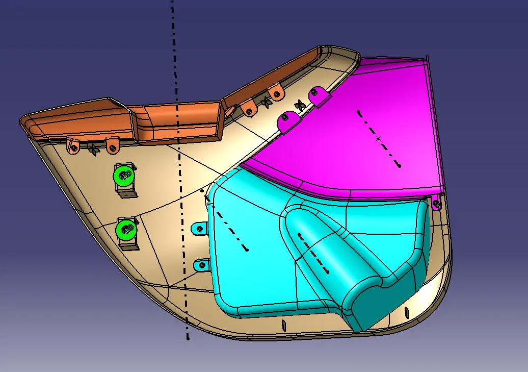
conclusion:
The Design of The Automotive Door Trim Panel from a Class A surface to a Closed Part Body with all the necessary attachment features by following all the design rules using CATIA V5 is done Successfully and all the required CATPart and CATProduct files are attached.