Week 12- Final project
Aim :- Development of a Door Trim panel
Objective :-
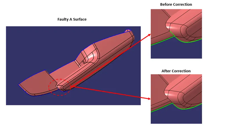
- First of all, repair faulty A class surface if any.
- Create tooling axis.
- They create Class B and Class C surface.
- Joint these surfaces and create close body.
- Create flanges for locators and heat stakes on every part according to assembly part requirement.
- Create engineering features like Dog house, Heat stakes and Locators.
- Perform Draft analysis of individual part.
Mater Section with Cross Section :-
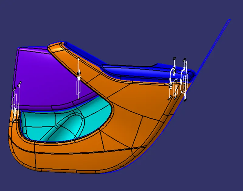
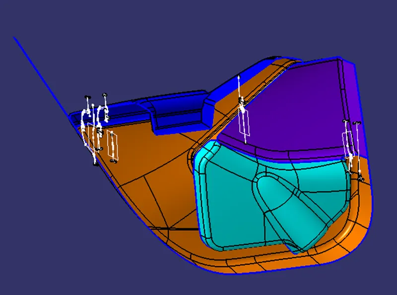
Arm Rest :-
Surface A
Given Class A surface is faulty. Need to correct and fill the gap.
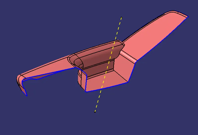
Tooling Axis
Tooling axis is must be feasible to inject component out easily during process.
Creation of Surface B
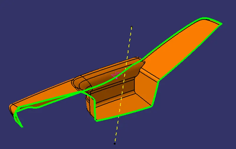
Class B surface is created by offsetting class A surface by 2.5 mm as per the master section. After offsetting some area not get offset, there patches formed. These patches are closed by surface creation features such as fill, multi section, blend etc.
Creation of Surface C
C surface is the connecting surface of Class A and Class B surface. By using Sweep, we created the Class C surface. For that first we have to extract Class A boundary and then with draft direction at angle 3 degree we have sweep the class A extracted boundary. And we get the Class - C surface.
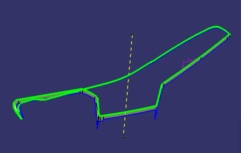
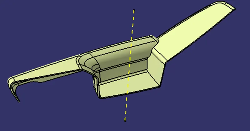
Creation of Close body and Converted in Solid Object
Creation of Flanges on Arm Rest
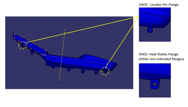
From master section we get the idea of flanges. I have created flanges on Arm Rest by considering Lower Substrate position.
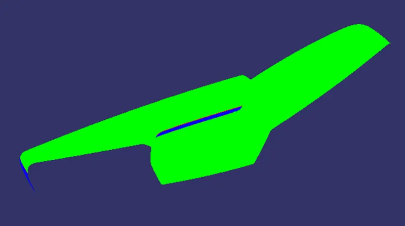
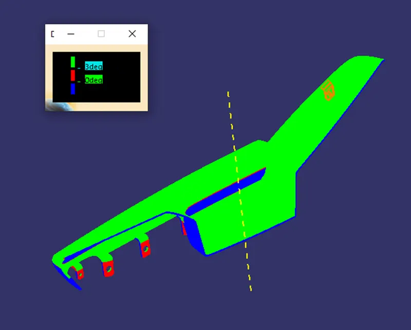
Draft Analysis
The draft is something that allows the component to release or eject from the mold properly. The draft is required on all parts in the direction of mold movement in order to allow parts to release properly. Most parts or applications require a minimum of 1/2 to 1 degree; however, 3 degrees is widely accepted as the norm.
The draft is given in the direction of tooling direction or core cavity opening.
If we don't give the draft to the component it struck to the mold and friction also act so we get the damage in our part so to overcome this we give some draft angle to overcome this problem.
Surface A Draft Analysis
Part Draft Analysis
Map Pocket :-
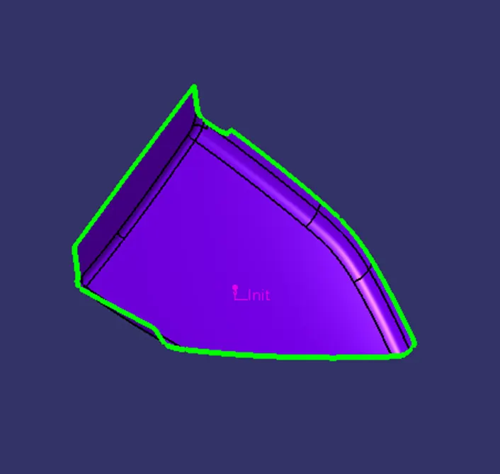
Surface A
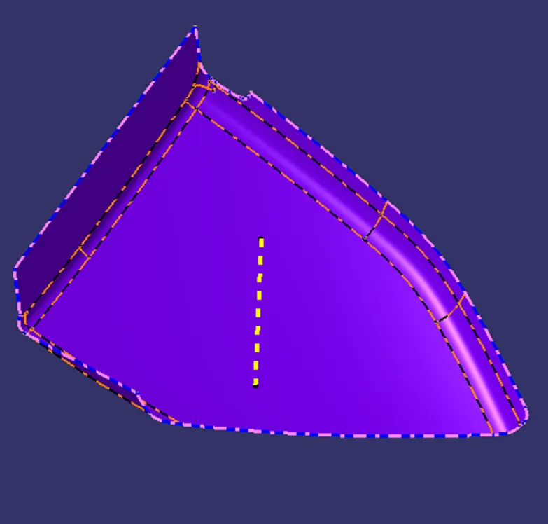
Tooling Axis
Tooling axis is must be feasible to inject component out easily during process.
Creation of Surface B
Class B surface is created by offsetting class A surface by 2.5 mm as per the master section. After offsetting some area not get offset, there patches formed. These patches are closed by surface creation features such as fill, multi section, blend etc.
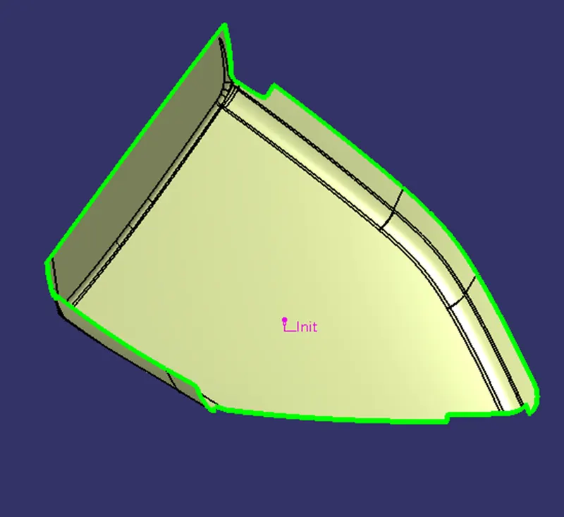
Creation of Surface C
C surface is the connecting surface of Class A and Class B surface. By using Sweep, we created the Class C surface. For that first we have to extract Class A boundary and then with draft direction at angle 3 degree we have sweep the class A extracted boundary. And we get the Class - C surface.
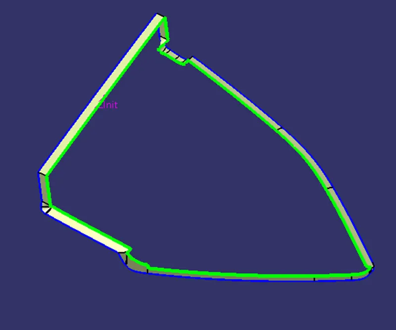
Creation of Close body and Converted in Solid Object
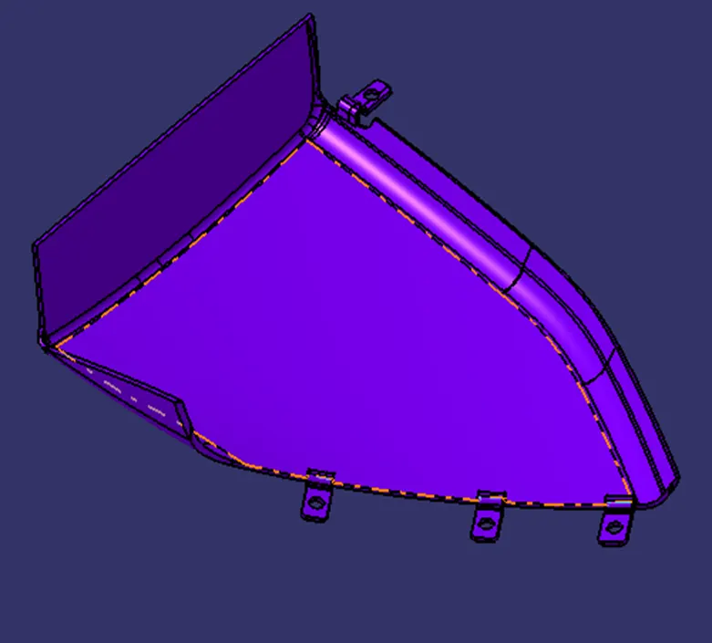
Creation of Flanges on Map Pocket
From master section we get the idea of flanges. I have created flanges on Arm Rest by considering Lower Substrate position.
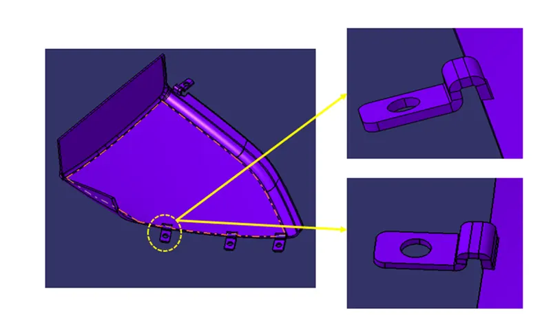
Draft Analysis
The draft is something that allows the component to release or eject from the mold properly. The draft is required on all parts in the direction of mold movement in order to allow parts to release properly. Most parts or applications require a minimum of 1/2 to 1 degree; however, 3 degrees is widely accepted as the norm.
The draft is given in the direction of tooling direction or core cavity opening.
If we don't give the draft to the component it struck to the mold and friction also act so we get the damage in our part so to overcome this we give some draft angle to overcome this problem.
Surface A Draft Analysis
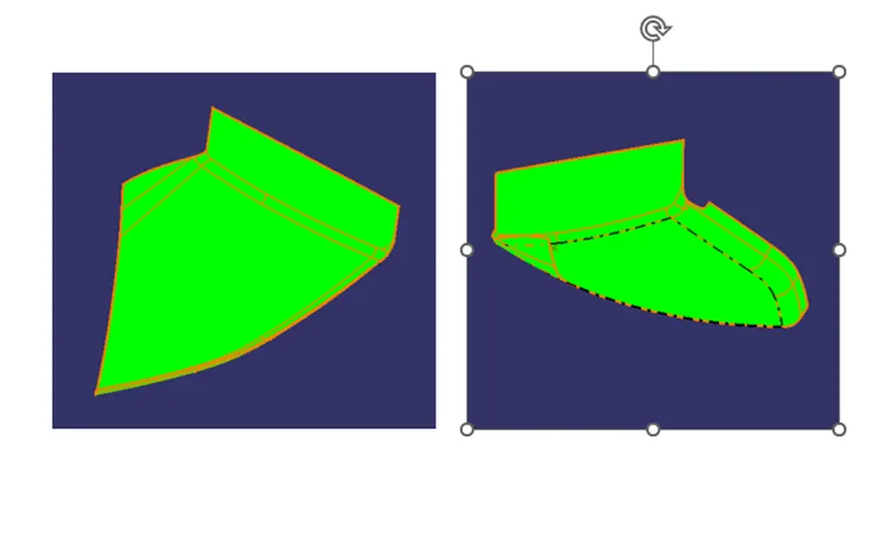
Part Draft Analysis

Bottle Holder :-
Surface A
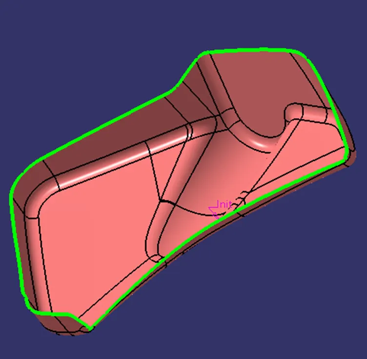
Tooling Axis
Tooling axis is must be feasible to inject component out easily during process.
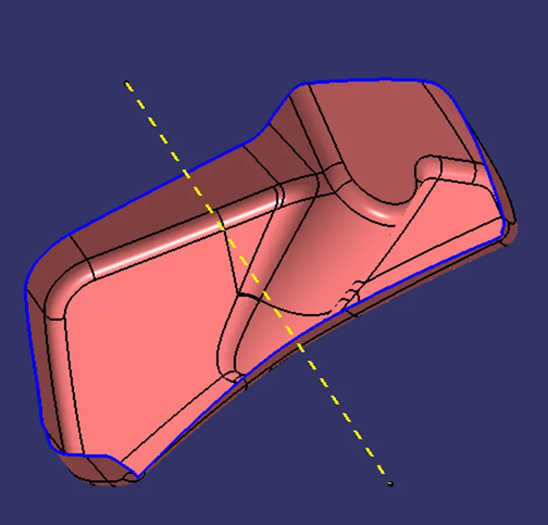
Creation of Surface B
Class B surface is created by offsetting class A surface by 2.5 mm as per the master section. After offsetting some area not get offset, there patches formed. These patches are closed by surface creation features such as fill, multi section, blend etc.
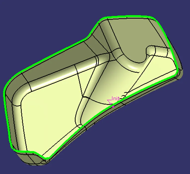
Creation of Surface C
C surface is the connecting surface of Class A and Class B surface. By using Sweep, we created the Class C surface. For that first we have to extract Class A boundary and then with draft direction at angle 3 degree we have sweep the class A extracted boundary. And we get the Class - C surface.
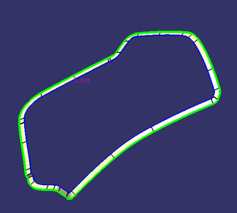
Creation of Close body and Converted in Solid Object
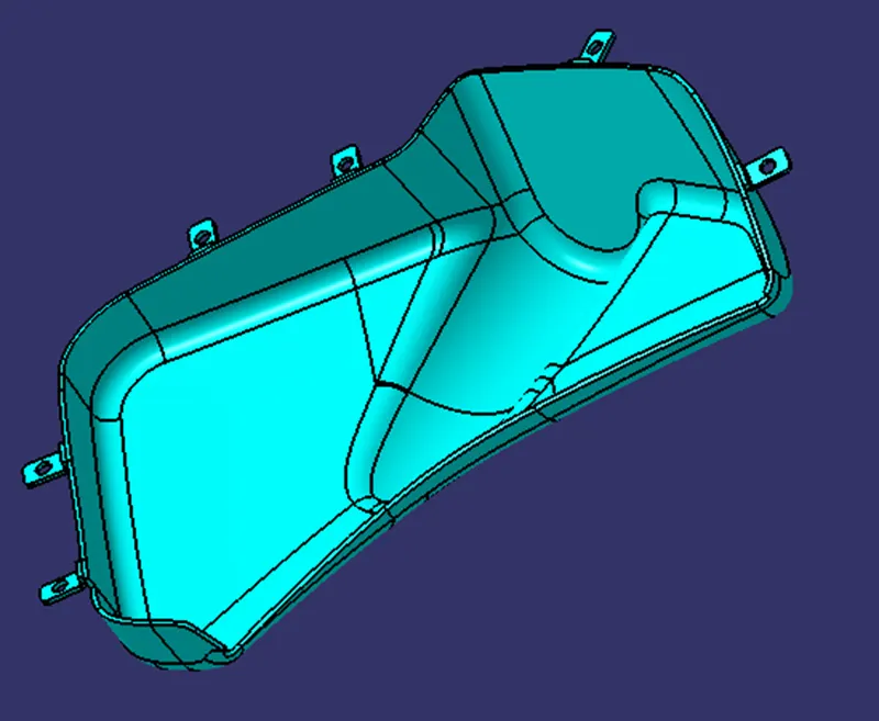
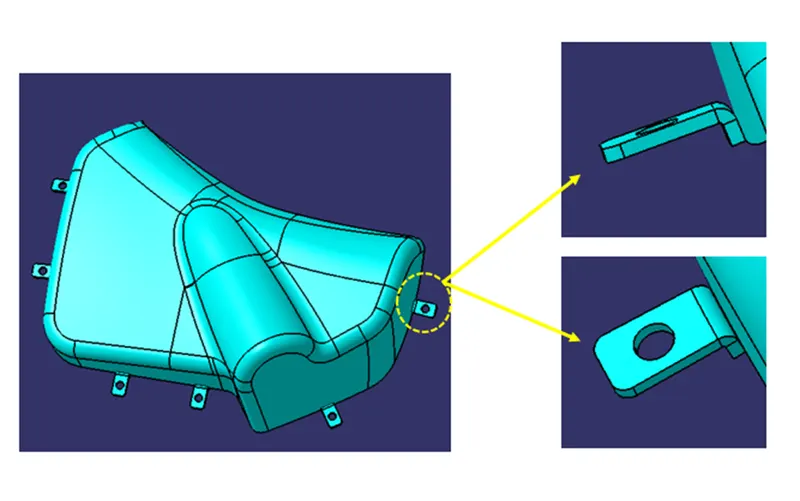
Creation of Flanges on Bottle Holder
From master section we get the idea of flanges. I have created flanges on Arm Rest by considering Lower Substrate position.
Draft Analysis
The draft is something that allows the component to release or eject from the mold properly. The draft is required on all parts in the direction of mold movement in order to allow parts to release properly. Most parts or applications require a minimum of 1/2 to 1 degree; however, 3 degrees is widely accepted as the norm.
The draft is given in the direction of tooling direction or core cavity opening.
If we don't give the draft to the component it struck to the mold and friction also act so we get the damage in our part so to overcome this we give some draft angle to overcome this problem.
Surface A Draft Analysis
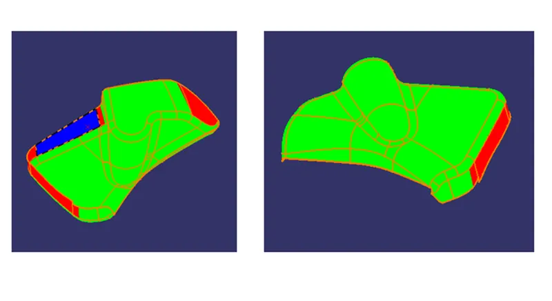
Part Draft Analysis
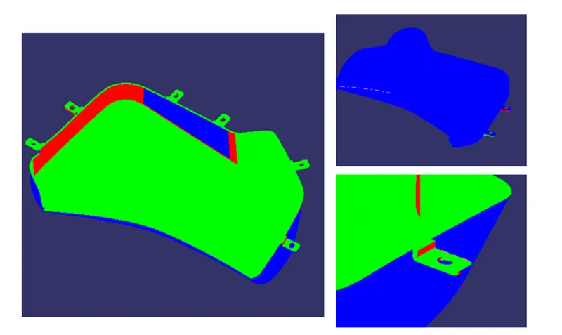
Lower Substrate :-
Surface A
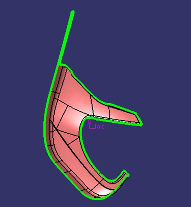
Tooling Axis
Tooling axis is must be feasible to inject component out easily during process.
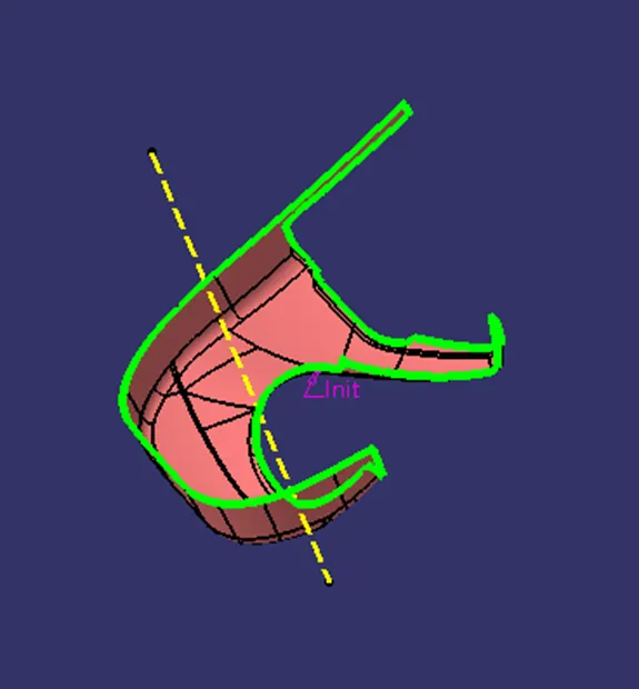
Creation of Surface B
Class B surface is created by offsetting class A surface by 2.5 mm as per the master section. After offsetting some area not get offset, there patches formed. These patches are closed by surface creation features such as fill, multi section, blend etc.
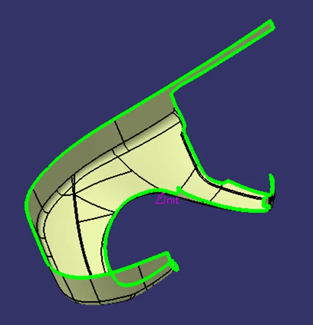
Creation of Surface C
C surface is the connecting surface of Class A and Class B surface. By using Sweep, we created the Class C surface. For that first we have to extract Class A boundary and then with draft direction at angle 3 degree we have sweep the class A extracted boundary. And we get the Class - C surface.
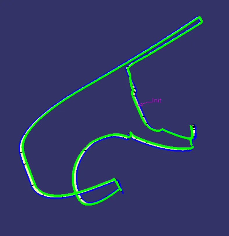
Creation of Close body and Converted in Solid Object
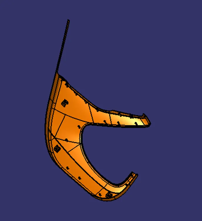
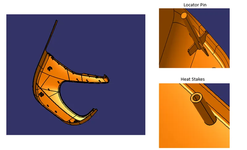
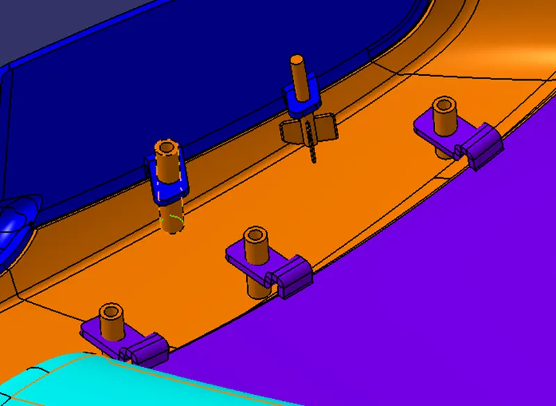
Creation of Heat Stakes and Locators
Heat stakes are used to join two different parts with each other. While locators are used to locate part at correct position while assembly.
Here there are two locators for arm rest and other are heat stakes to join door trim parts using flanges.
One of the important factors to be considered while designing the heat skates is the height of the heat skates. It should always be less than the height of the locators.
Creation of Dog House
The two main purposes of a dog house are to avoid sink marks and to house various other engineering features like screw boss, locators, push clips etc.
In this case, the dog house is designed to house the push clips and the 4-way locator. The dog house designed for the push clip features a slot on the top face to accommodate the push clip
The dog house should follow certain design rules which are stated below
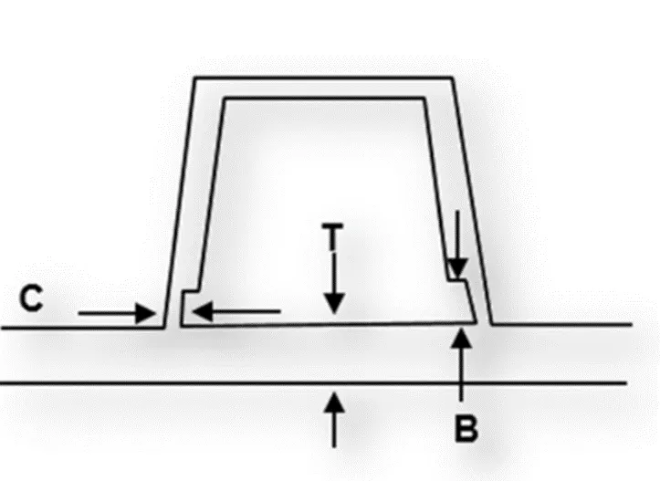
Doghouse wall thickness at the intersection of the part wall (C) should be 40% or less than the main wall stock (T).
The height of ( B ) should be between 3.0 – 6.0 mm
Outer surface of dog house must have a draft angle of 3 degrees
Inner surface of dog house must have a draft angle of 0.5 degrees
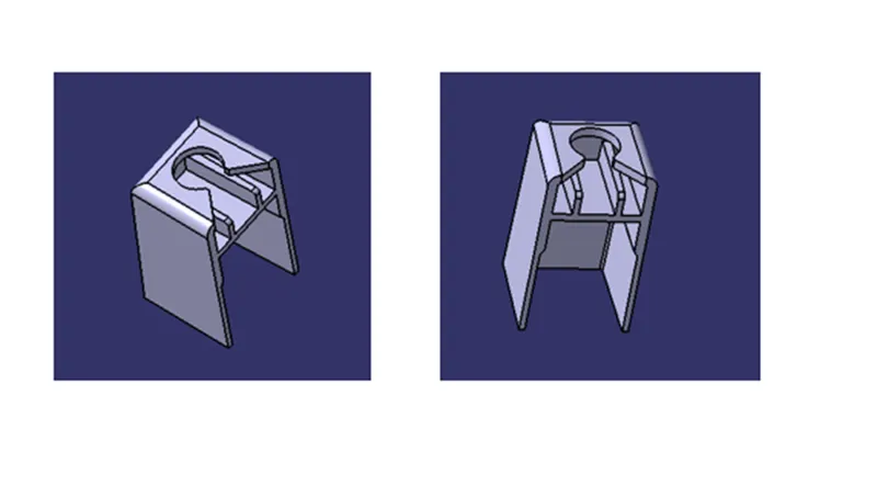
Draft Analysis on Dog House
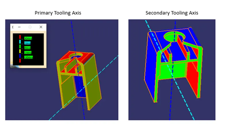
Draft Analysis
The draft is something that allows the component to release or eject from the mold properly. The draft is required on all parts in the direction of mold movement in order to allow parts to release properly. Most parts or applications require a minimum of 1/2 to 1 degree; however, 3 degrees is widely accepted as the norm.
The draft is given in the direction of tooling direction or core cavity opening.
If we don't give the draft to the component it struck to the mold and friction also act so we get the damage in our part so to overcome this we give some draft angle to overcome this problem.
Surface A Draft Analysis
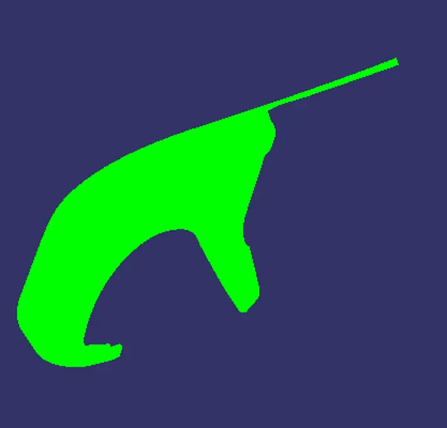
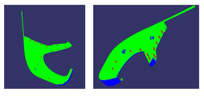
Part Draft Analysis
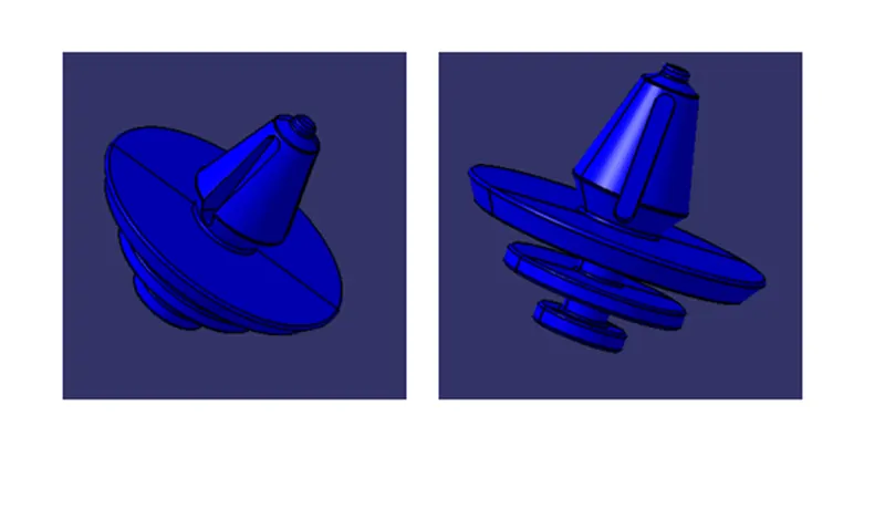
Push Pin Design
Push pin is used to assemble to different part easily just by push and lock.
In grooves part is fixed and tip part is inserted where ever need join that part with other part.
Final Assembly : -
For final assembly of door trim panel we have to constraint all parts together.
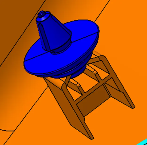
Following image shows the assembly of push pin with dog house.
All Part Assembly
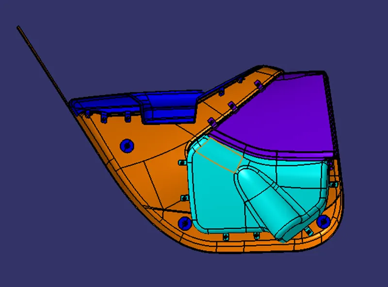
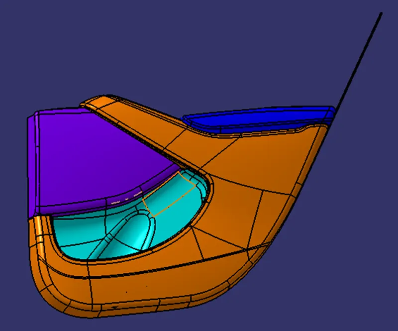
This is how parts are created and get assembled.