Week 12- Final project
PROJECT REPORT
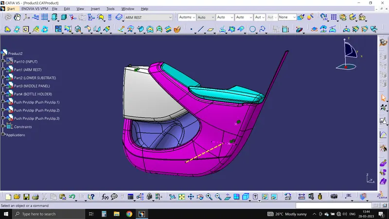
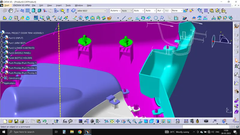
OBJECTIVE: To create an assembly of DOOR TRIM components from given CLASS A inputs, with additional attachment engineering features such as Heat stakes, Dog House and Locators following the design rules and OEM industry standards.
SOFTWARE USED: Catia V5
PROJECT PREVIEW:
INPUTS:
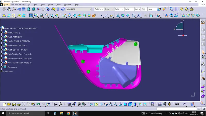
- Arm Rest Class A (Light Blue Colour).
- Lower Substrate Class A (Pink Colour).
- Middle panel Class A (White colour).
- Bottle Holder Class A (Dark Blue colour).
- Master Sections.
DEVELOPMENT OF SURFACES:
1. ARM REST:
- TOOLING AXIS CREATION:
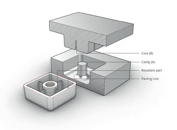
A tooling axis refers to the axis which a core and cavity of mold follows in the production of a plastic component.
Two axis are generally used in the development of surfaces
1. Main tooling axis which is axial movement of moulds into each other.
2. Side core axis which represents the axis which a sliding core moves with respect to the feature which could not be accomodated in main tooling axis movement direction.
Tooling axis are created using the following methods:
1. Bisection method.
2. Point and Direction.
3. Normal to surface.
- CLOSED SURFACE CREATION:
Using class A surface, First check for any discontinuity in the surface.
If there is any then it has to be resolved as a continous surface using extraction, extrapolation, untrim, and trim operations.
Now for CLASS B surface creation, It has to be offsetted to desired thickness ie. 2.5mm.
Again we need to develop the CLASS B surface using extraction, extrapolation, untrim, and trim operations.
Ensure to define the operations in defined Geometrical Sets.
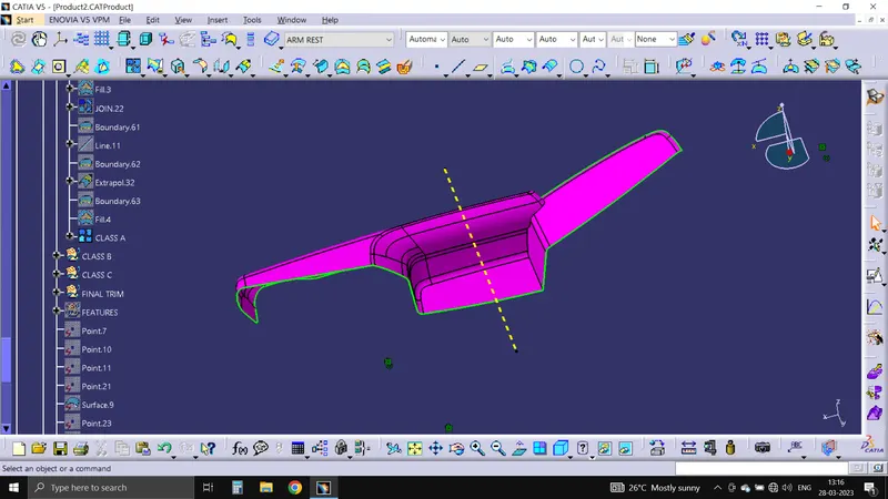
CLASS C creation, outer boundry of class a surface is extracted and sweeps around the class a surface either in parts or as whole.
The sweeps are created using two methods:
1. With draft direction
2. with reference to surface.
CLASS A SURFACE:
FINAL CLOSED SURFACE:
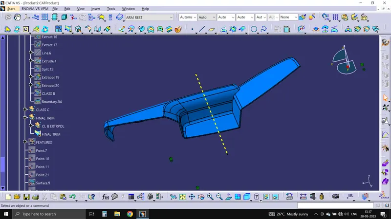
After creation of class A, class B and class C surfaces. First class a is joined with the class c surface.
Then it is trimmed with class B surface to get a closed surface as final output.
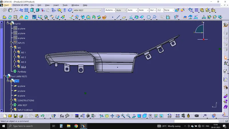
FINAL PART BODY:
Shown is the view of my final output as solid part body created using Closed surface feature in part workbench.
It has all the features which will be used to join with other component.
DRAFT ANALYSIS:
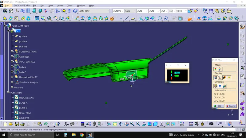
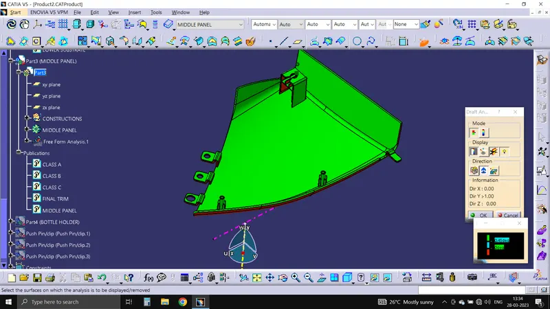
Class A surface analysis is done before the solid part body. the minimum draft is set as per standard is 3 degrees. its been observed that the given CLASS A surface is a green color having some red patched portions. angles of different surfaces are checked and noted.
After surfacing the class A with CLASS C, joining them as a whole, and trimming the joined class A surface with the Class B surface gives off the desired thickness of the component.
draft analysis is done on the closed solid part body after the final trim.
C surface here in this case is 90 deg to the tooling axis created using multiple boundry extractions and sweeping them with reference to surface option.
others are created using with draft direction feature providing draft with reference to tooling axis. then to combine the class c extracts to a continous surface we have to extrapolate and trim the extracts with each other.
TOOLING AXIS: First of all, the details like taper faces and hole complexities are checked. then the faces are chosen that easily accommodate with the movement of the core and cavity which is my tooling axis path. It is usually perpendicular to the part. An intersection is drawn with a plane perpendicular to the cross-section of the class A surface. But i have used POINT AND DIRECTION tooling axis method which cleared my all surfaces without problem.
(HERE POINT AND DIRECTION(Y- AXIS) METHOD IS DEFINED ABOVE WITH MY PROCEDURE)
if there are more drafted faces are there in part then the two to three dummy axis is drawn and their bisection is taken keeping the angles not less than 3 degrees.
THICKESS of component is 2.5 mm as mentioned.
Pulling direction for all the features are given to TOOLING AXIS. also on the draft analysis of the final component.
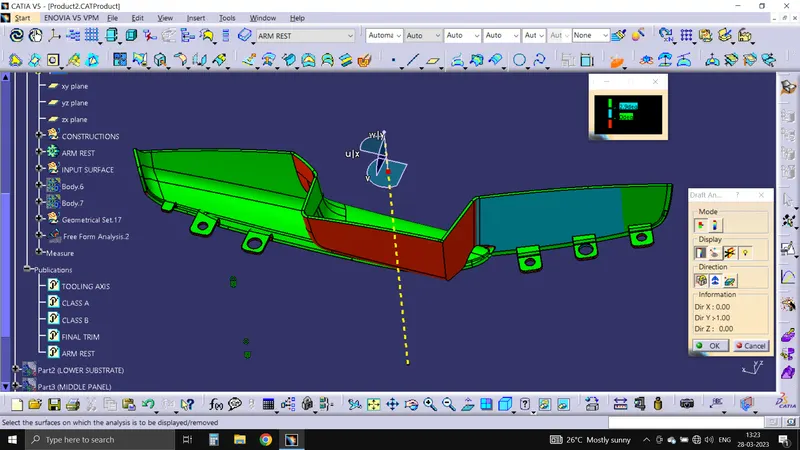
Keeping the angle to 0.5 deg all the engineering attachment features have cleared the test.
Draft angle for all the features i.e. HEAT STAKES & LOCATORS given as 0.5 degrees per face with respect to the main tooling and side tooling axis.
Draft analysis of final output keeping draft angle as 2.9 deg.
DRAFT ANALYSIS FOR ENGINEERING FEATURES: DRAFT ANGLE AS 0.45 Deg.
2. LOWER SUBSTRATE:
In the same way as described above we have to develop and create all the surfaces for rest of the inputs.
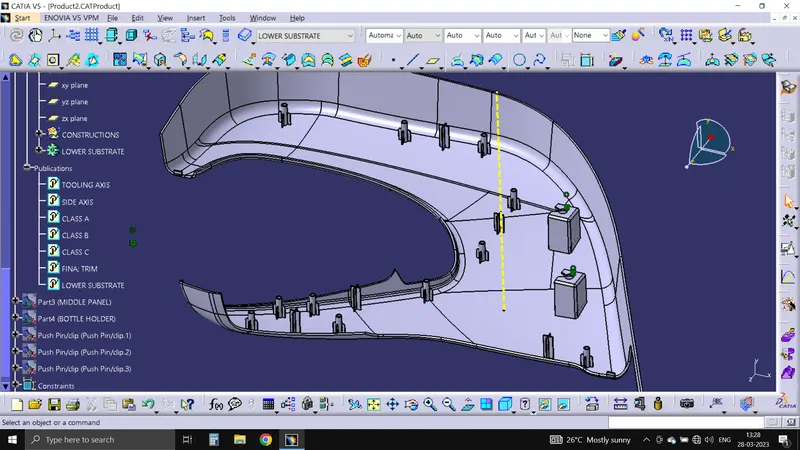
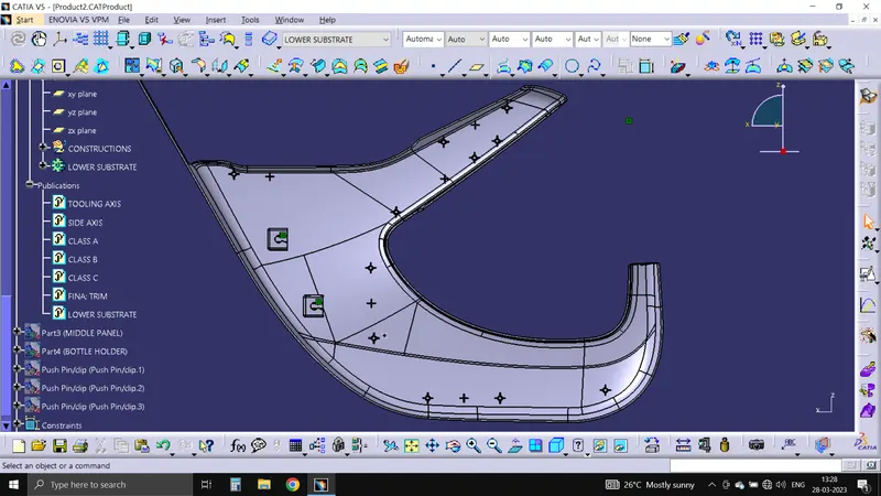
CLASS A:
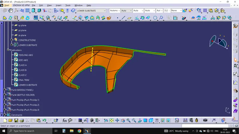
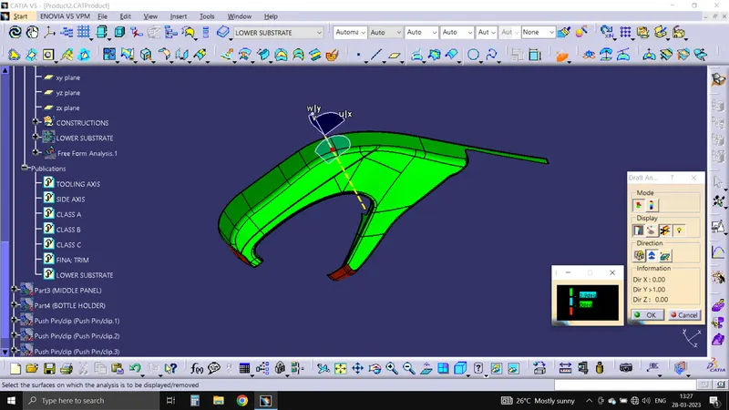
CLASS A DRAFT ANALYSIS: Clearing all surfaces at 2.9 deg.
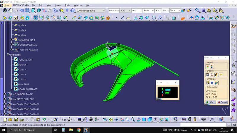
DRAFT ANALYSIS OF FINAL COMPONENT: 2.9 DEG.
3. MIDDLE PANEL:
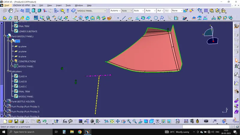
CLASS A:
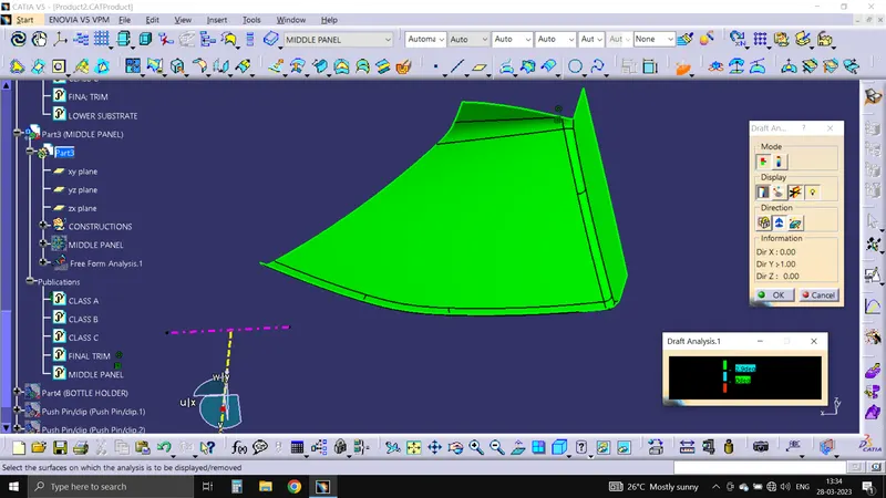
DRAFT ANALYSIS OF CLASS A AT 2.9 DEG.
FINAL CLOSED SURFACE:
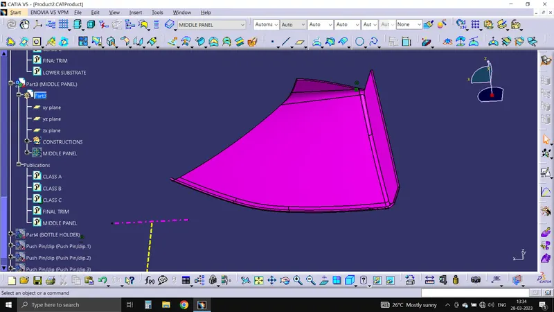
DRAFT ANALYSIS OF SOLID BODY:
4. BOTTLE HOLDER:
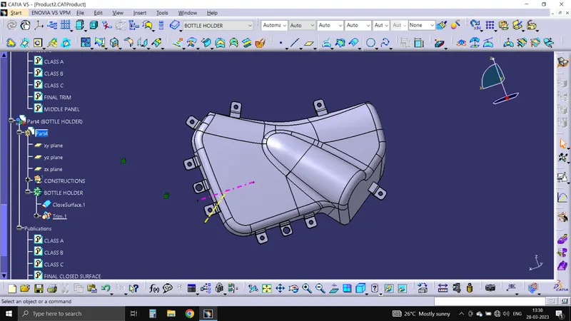
CLASS A:
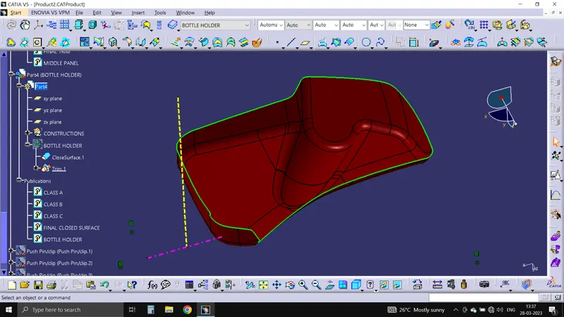
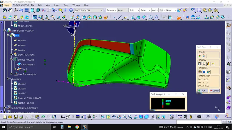
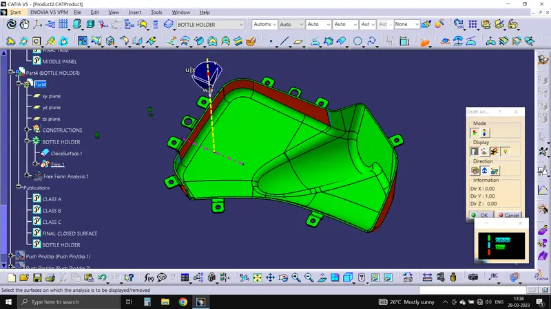
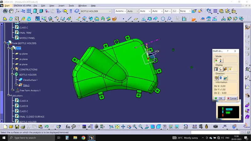
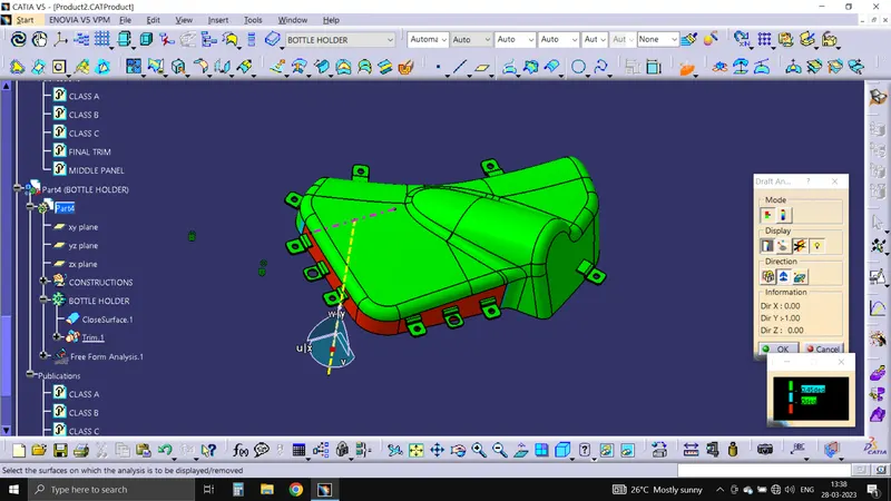
DRAFT ANALYSIS OF CLASS A SURFACE:
It has been observed that given input has some red patches which is not clearing the draft analysis because these faces have no draft provided by Class A engineer.
draft angle of these faces are 0 degree.
FINAL COMPONENT:
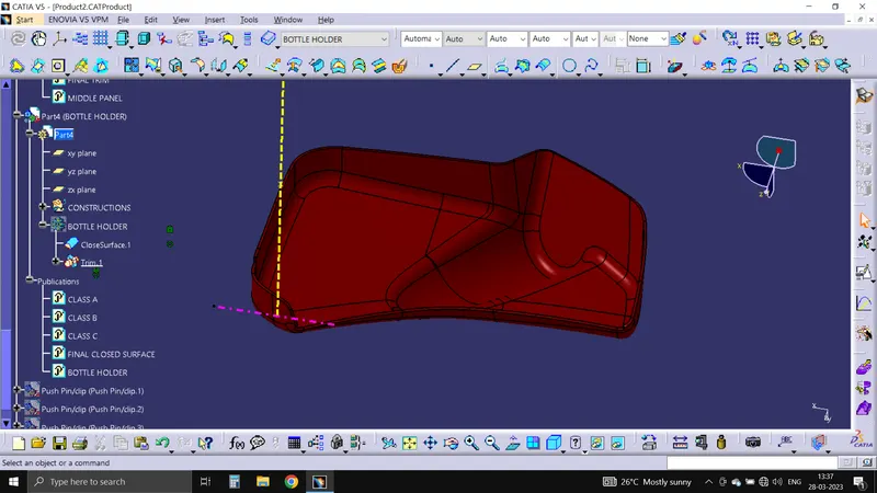
DRAFT ANALYSIS OF SOLID BODY WITH ENGINEERING FEATURES:
CREATION OF ENGINEERING FEATURES:
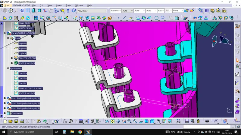
1. HEAT STAKES:
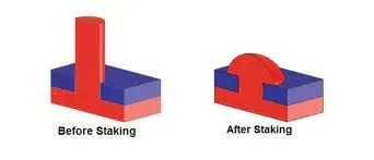
Heat staking is a process used to join two plastic components by partially melting and reforming the thermoplastic material. The process involves applying heat to a specific point on one component, then pressing it against the other component until the melted material cools and solidifies, creating a permanent bond between the two pieces.
Heat stakes, also known as heat bosses, are small protrusions on plastic components that are used as anchors for the heat staking process. These stakes are designed to melt and reform when heat is applied, creating a secure attachment point between the two components.
Heat staking is commonly used in the manufacture of plastic products, particularly in the automotive, electronics, and consumer goods industries. It is an effective method for creating strong, durable joints between plastic components, and can be used to join dissimilar materials as well.
heat staking is a useful joining method for certain plastic components, particularly those with simple joint designs and low strength requirements.
DRAFT is also peovided as per design rules 0.5 deg.
DESIGN RULES:
Counter Part Thickness - Will be given as input
● Component Wall Thickness - Will be given as input
● Length of the Rib - 22 mm
● Height of the Ribs - 3 mm to 6 mm
● Inner Diameter of Heat Stake (d) - 5 mm
● Outer Diameter of Heat Stake (d) - 7 mm
● Minimum clearance between heat stake and counterpart - 0.5 mm
● Height of the Heatstake - Depends on the rib height and counter part thickness
● Minimum fillet of Heat Stakes - 0.25 mm
● Minimum Draft Angle of Heat Stakes - 0.5 degrees
2. LOCATORS:
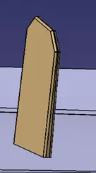
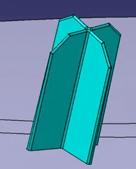
Locators are small features or protrusions on plastic components that are used to precisely position and align the components during assembly. These features help ensure that the components are correctly oriented and located relative to each other, which can improve the overall quality and functionality of the finished product.
Locators can take a variety of forms, including pins, slots, holes, and bumps, depending on the specific application and assembly requirements. They are typically designed to fit together in a precise and repeatable manner, allowing for efficient and accurate assembly.
In plastic components, locators are often used in conjunction with other joining methods, such as snap-fit connections, adhesives, or heat staking, to create secure and precise assembly of the components. By providing a precise and repeatable location for the components to be joined, locators can help ensure consistent and reliable assembly of the final product.
DESIGN RULES:
Height of the locators should be 1 mm (or) 2 mm greater than the heat stakes
● Thickness, fillet and draft angle are of same as rib design rules.
● Ideal Chamfer value - 5 mm x 45 degrees
● Ideal length of the locators - 15 mm
2 WAY LOCATOR
4 WAY LOCATOR
3. DOG HOUSE:
A dog house made of plastic components is a durable and weather-resistant option for providing a comfortable and secure shelter for your pet. Plastic dog houses are lightweight, easy to clean, and resistant to rot, mold, and pests, making them a popular choice for pet owners who want a low-maintenance solution for their dogs.
Plastic dog houses can be manufactured using injection molding or other plastic fabrication techniques. The components are typically designed to fit together easily, and may include features such as snap-fit connections or interlocking panels to simplify assembly.
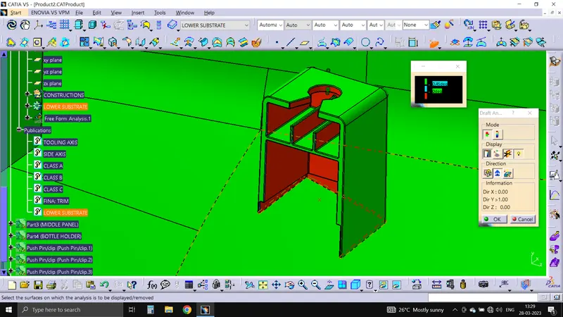
DRAFT ANALYSIS OF DOG HOUSE AT 0.45 DEG.
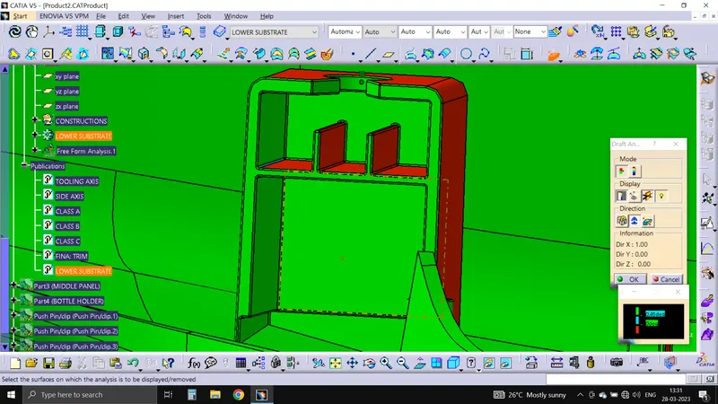
WITH SLIDER AXIS:
DESIGN RULES:
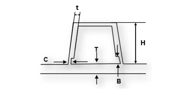
Height of the Dog House - Maxiumum of 55 mm
● Thickness of the Dog House (t) - Same as component wall thickness
● Coring Height (B) - 3 mm to 6 mm
● Coring Thickness (C) - 40% of Wall Thickness of the component
● Thickness of the Component - Given as input
● Length and Breadth of the Dog House can be decided upon the application
● Inner Fillet of Dog House (Thickness t) - 0.5 mm
● Outer Fillet of Dog House (Thicknes t) - t + 0.5 mm
● Inner Fillet of Dog House (Thickness C) - [ t + 0.5 mm] - 40% of Wall Thickness
● Outer Fillet of Dog House (Thicknes C) - t + 0.5 mm
● Fillet for the Corting Face - 0.25 mm (or) 0.3 mm
● Draft Angle for Dog House - 0.5 degrees (both outer & inner)
4. MASTER SECTIONS:
A master section is a detailed, scaled drawing or model of a component or system that is used as a reference or template for creating the final product.
In the automotive industry, master sections are often used to create accurate 3D models of the vehicle's structural components, such as the body-in-white, chassis, and suspension. These models are then used to design and test various subsystems and components, such as the powertrain, electrical system, and interior.
The use of master sections in automotive design allows for a more efficient and precise design process. By creating detailed 3D models of the vehicle's structural components, designers can quickly and easily test and refine different design options and evaluate their impact on the overall vehicle performance and functionality.
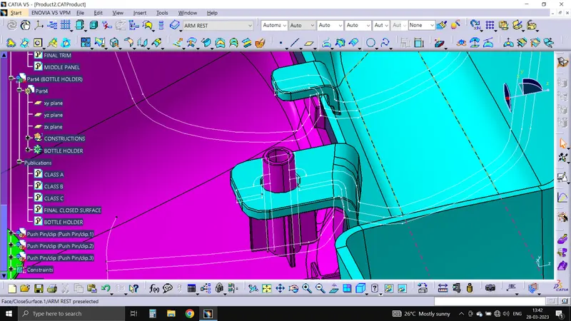
FINAL ASSEMBLY VIEWS: