Week 8 - Challenge 4 - Bumper
REPORT:
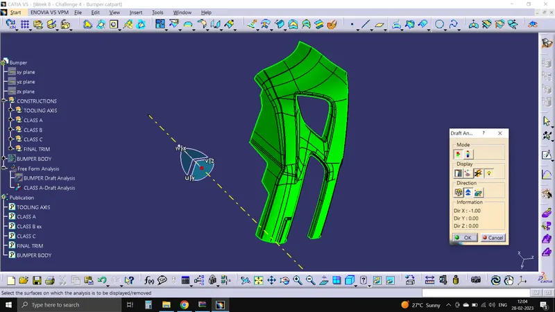
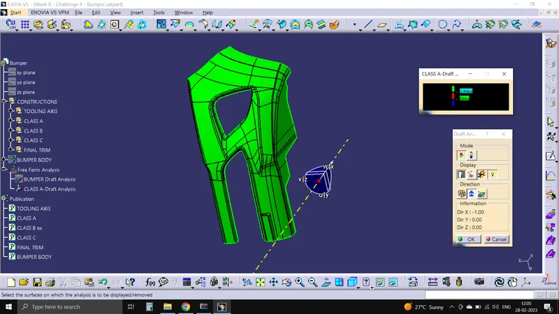
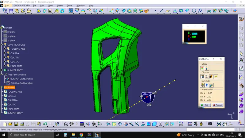
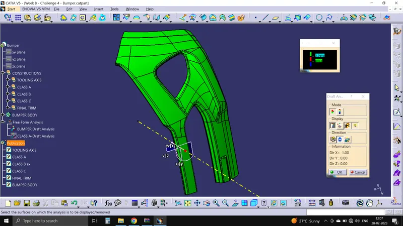
DRAFT ANALYSIS: Class A surface analysis is done before the solid part body. the minimum draft is set as per std 3 degrees. its been observed that the complete class surface is a green color having no red patched portions. angles of different surfaces are checked and noted.
after surfacing the class A with CLASS C, joining them as a whole, and trimming the joined class A surface with the Class B surface gives off the desired thickness of the component.
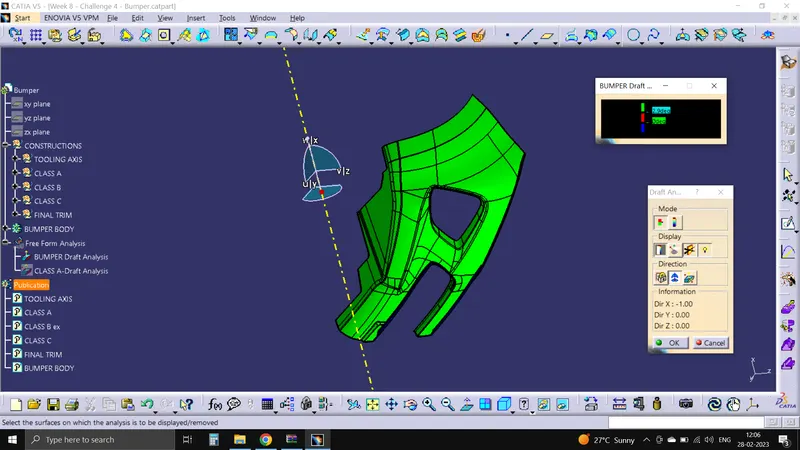
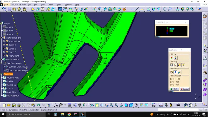
draft analysis is done on the closed solid part body after the final trim. The top and bottom have cleared the test having draft angle minimum of 3 deg value.
C surface here in this case is 90 deg to the tooling axis created using multiple boundry extractions and sweeping them with reference to surface option. others are created using with draft direction feature providing draft with reference t tooling axis. then to combine the class c extracts to a continous surface we hace to extrapolate and trim the extracts with each other.
TOOLING AXIS: First of all, the details like taper faces and hole complexities are checked. then the faces are chosen that easily accommodate with the movement of the core and cavity which is my tooling axis path. It is usually perpendicular to the part. An intersection is drawn with a plane perpendicular to the cross-section of the class A surface. But i have used NORMAL TO SURFACE tooling axis method which cleared my all surfaces without problem.
(HERE NORMAL TO SURFACE METHOD IS DEFINED ABOVE WITH MY PROCEDURE)
if there are more drafted faces are there in part then the two to three dummy axis is drawn and their bisection is taken keeping the angles not less than 3 degrees.
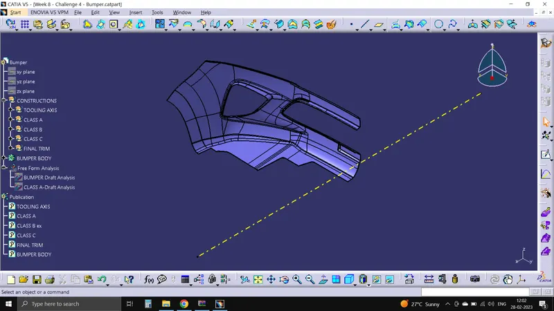
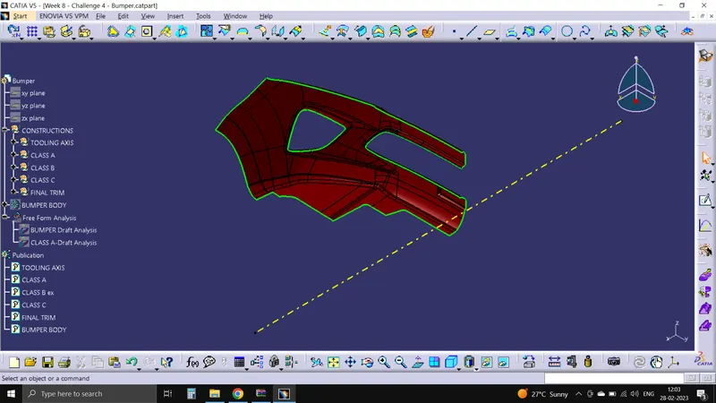
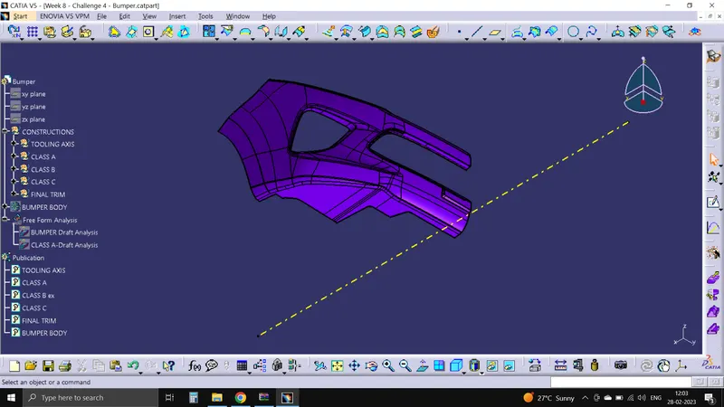
DRAFT ANALYSIS- CLASS A AND FINAL PLASTIC COMPONENT