Week 12- Final project
AIM: Creation of CAD model considering following inputs as like in OEM and tier1 companies
- Class A surface
- Nominal thickness
- Attachment strategy
Draft analysis: Draft analysis refers to the evaluation and examination of designs or technical drawings to assess their suitability for manufacturing or construction purposes. It involves analyzing the dimensions, tolerances, geometry, and other specifications of a design to ensure its functionality, manufacturability, and adherence to industry standards.
To evaluate the component, we must follow the below steps.
Step 1:
- Verify the Connectivity of the Class A Surface to Make sure there are no gaps between the components by using the join command.
- Perform a visual inspection or click on the boundary command and obtain the boundary lines of the component.
As a result, the initial check has been completed.
Step 2:
- Determine the Tooling Axis of the Component. The tooling axis refers to the direction in which the mold or cavity opens.
- Evaluate visually to identify the most suitable tooling axis.
- Examine all three axis and create the tooling axis in the feasible direction using appropriate method.
As a result, we have determined the temporary tooling axis.
To Create the Engineering Features such as Ribs, Boss and Supports the Draft Angle of 0.5 Degree is used as the Standard Value.
Step 3:
- Use the temporary tooling axis.
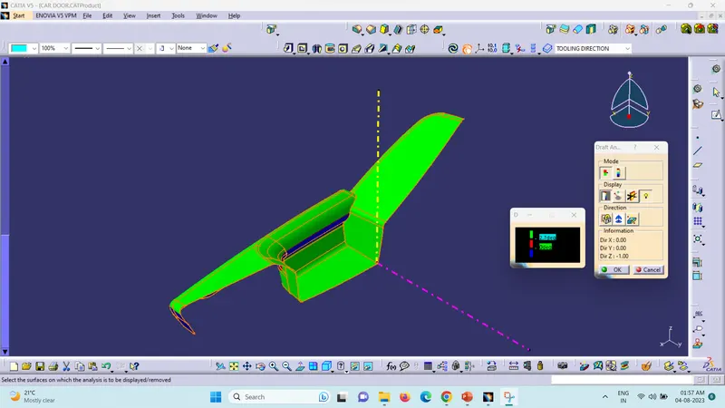
- Perform a Draft analysis using the Featured Draft Analysis tool in the software.
- Open the draft analysis toolbox.
- Locate the compass tool and place it aligned with the tooling axis.
- Align the compass precisely and click on the lock symbol to secure its position.
- Click on the surface you want to analyze or apply the draft to.
Step 4:
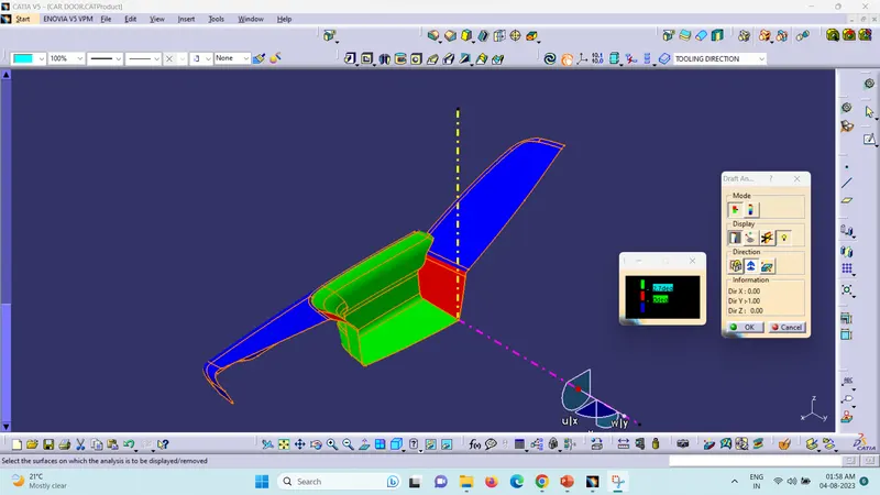
- As we have the result of the draft analysis, we will check whether the draft is positive or negative.
- If the draft is positive, then we will move on to create the Class B and Class C surfaces.
- If the draft is negative, we will try to create new tooling axis using other methods and perform the draft analysis again.
- If a positive draft is achieved, then we will move on to create the Class B and Class C surfaces.
- If the positive draft is not achieved, feedback is given to the styling team to modify the Class A Surface.
- After getting the new Class A Surface, we have to perform the same steps from 1 to 4 again.
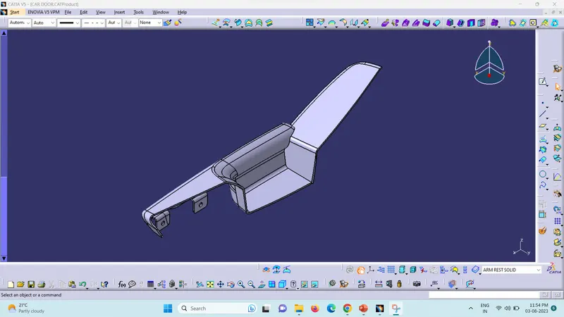
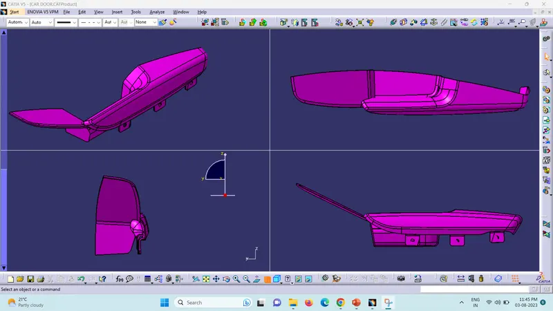
Draft Analysis - Arm Rest
1. Class A Surface with 3 Degree Nominal Draft Angle
2. Plastic Complonent and Different Views
Draft Analysis - Lower Substrate
1. Class A Surface with 3 Degree Nominal Draft Angle
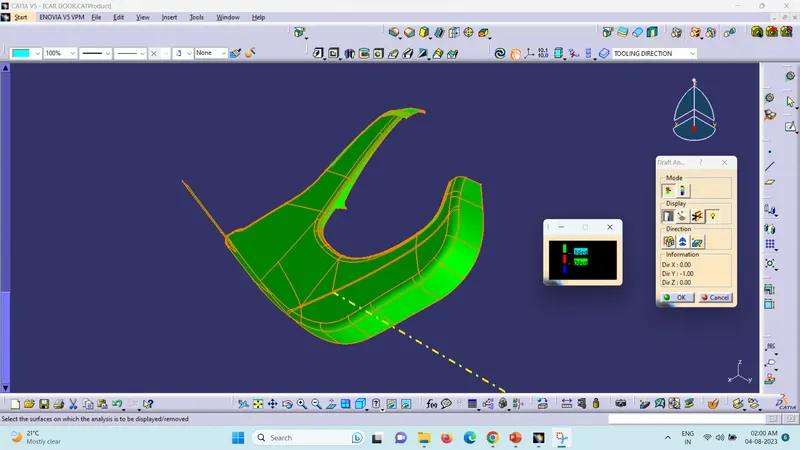
A. Draft Analysis - Dog House with 0.5 Degree Nominal Draft Angle
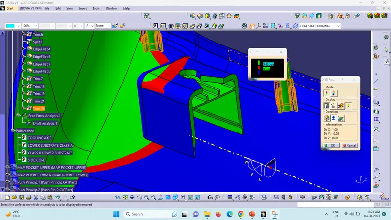
B. Draft Analysis - Heat Stakes with 0.5 Degree Nominal Draft Angle.
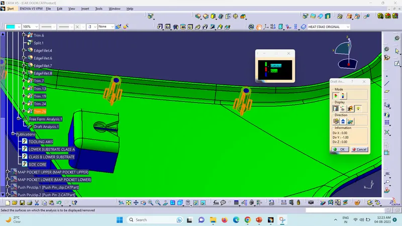
C. Draft Analysis - 4 Way Locator with 0.5 Degree Nominal Draft Angle.
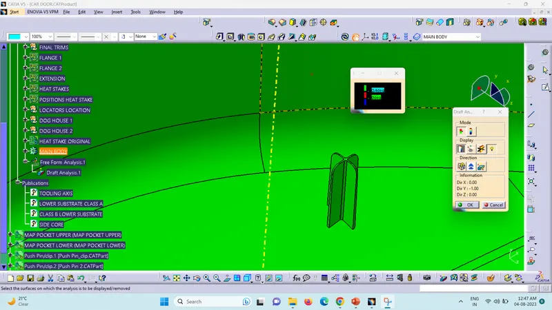
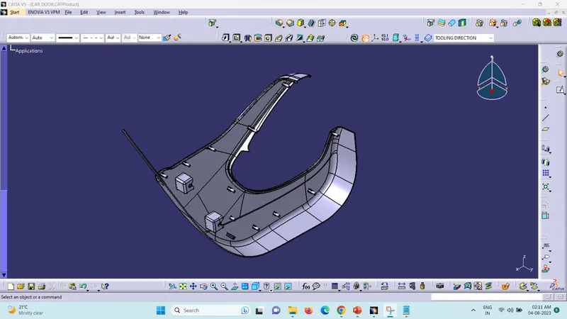
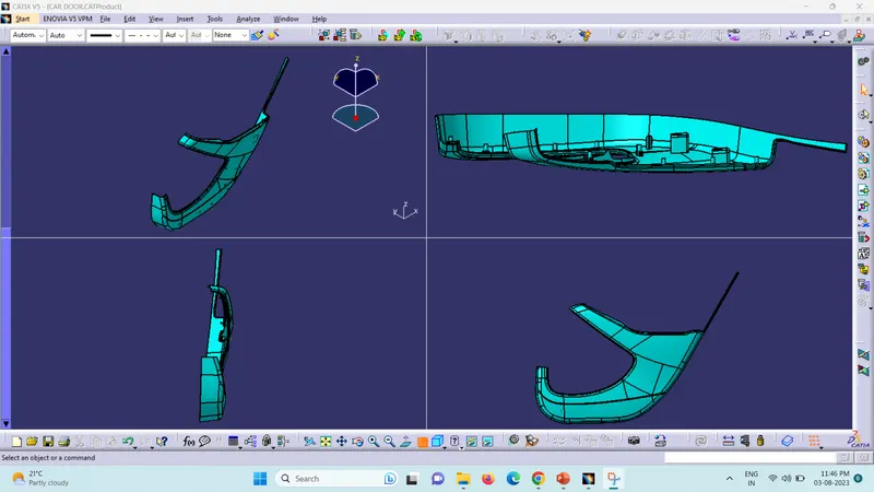
2. Plastic Complonent and Different Views
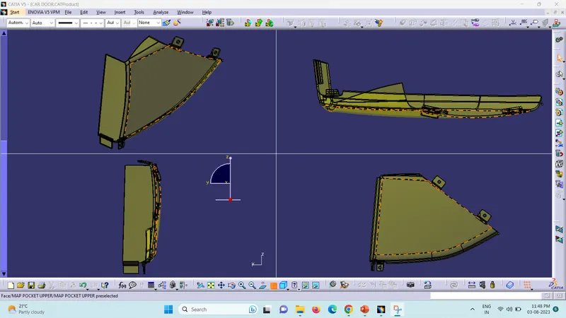
Draft Analysis - Map Pocket Upper
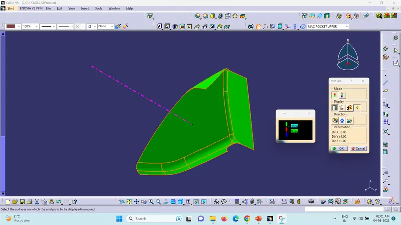
1. Class A Surface with 3 Degree Nominal Draft Angle
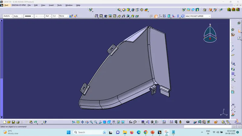
2. Plastic Complonent and Different Views
Draft Analysis - Map Pocket Lower
1. Class A Surface with 3 Degree Nominal Draft Angle
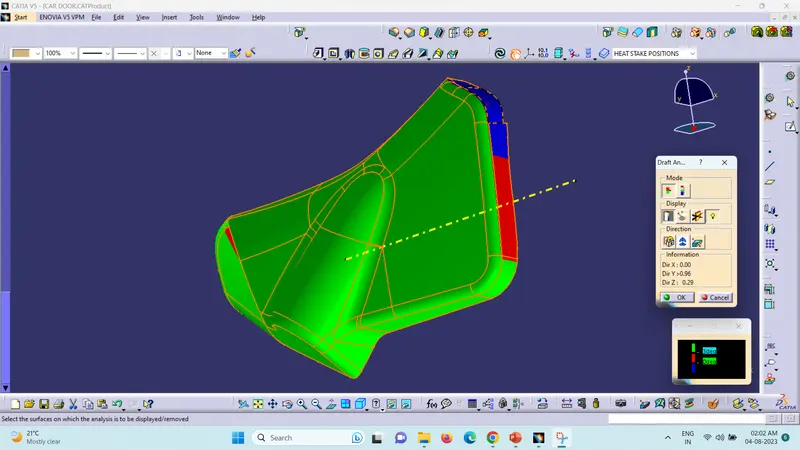
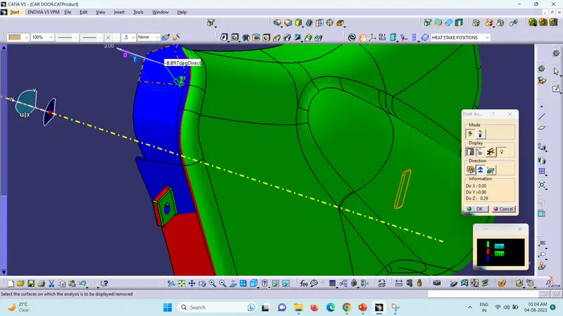
2. Class A Surface with -8.9 Degree Minimum Draft Angle (To be sent to styling team and get the Improve Class A Surface)
3. Plastic Complonent and Different Views
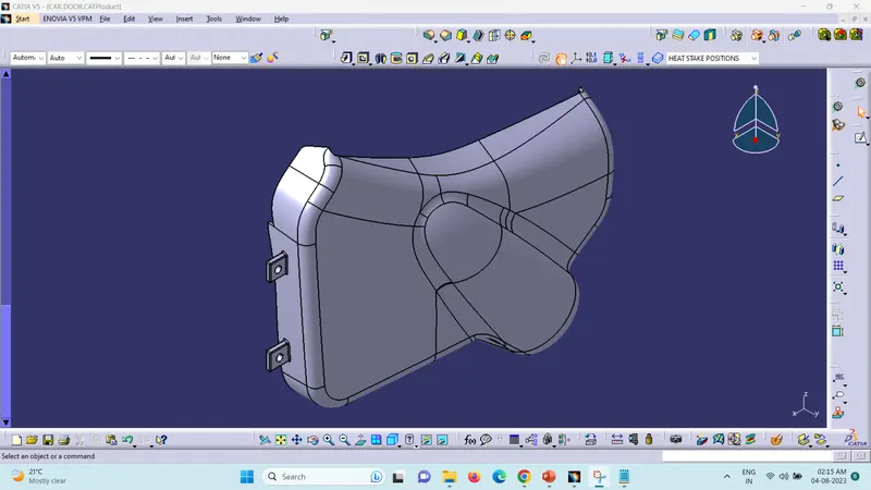
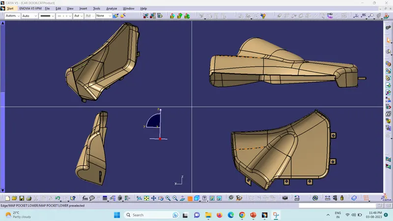
ASSEMBLY AND VIEWS
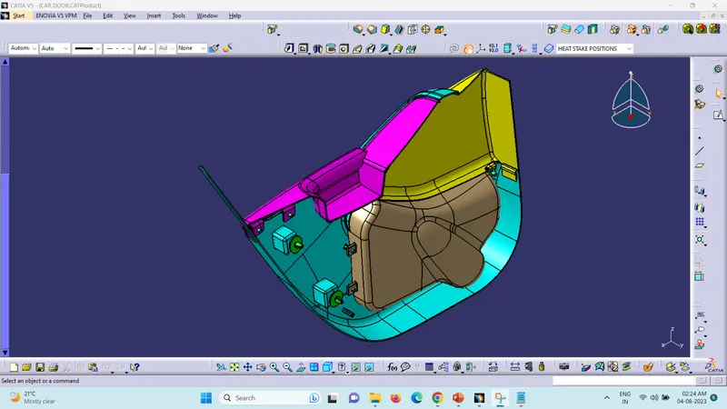
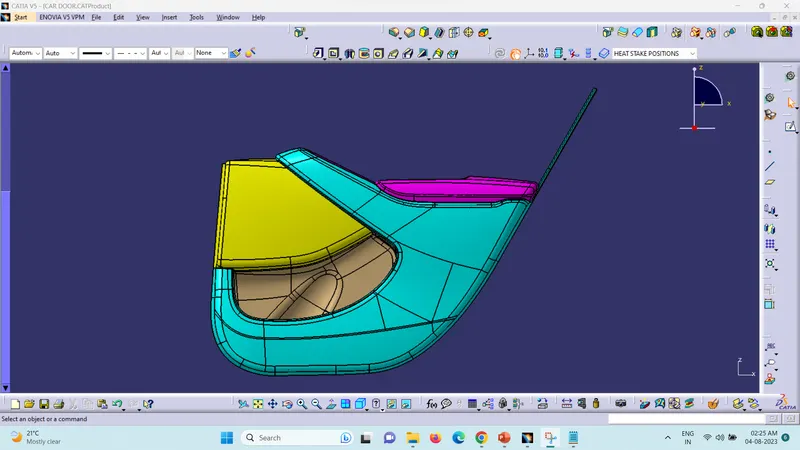
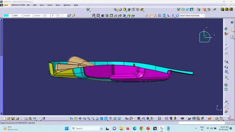
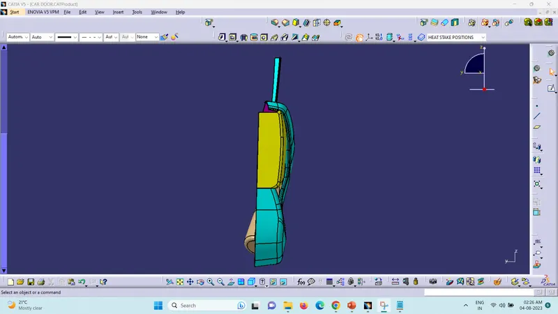
CONCLUSION - Thus we have the developed Door Panel with nominal thickness of 2.5mm.