Week 12- Final project
REPORT WRITING ON DOOR TRIM (FINAL PROJECT) BASED ON DRAFT ANALYSIS
TOOLING AXIS, DRAFT ANALYSIS ON CLASS A SURFACE OF LOWER SUBSTRATE:
In order to perform the drafting analysis, the first step is to create the main tooling axis for the given class-A surface. First I have extracted one of the surface patches, which is suitable for creating the main tooling axis. Then created the point on the extracted patch using point type as ‘On surface’ option. Once the point is created on the surface, the next step is to draw the dummy tooling axis. For lower substrate, the dummy tooling axis is considered as main tooling axis, as there are no edges in perpendicular plane to bisect the lines passing through the edges. Also for more details, refer to the figures mentioned below.
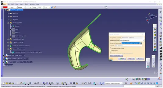
Figure represents the extraction of flat surface of lower substrate with no propagation for generating point on the surface
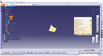
Figure represents the generation of point on the middle of the surface
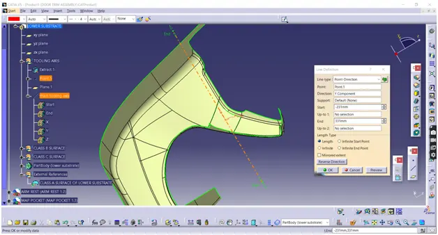
Figure represents the generation of dummy tooling axis, which is further considered as main tooling axis
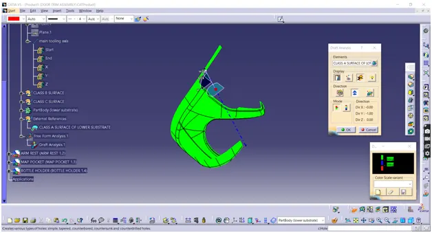
Now, once main tooling axis is generated, draft analysis is made on given class - A surface with 3 degree draft. And it was observed that given class - A surface is well designed for 3 degree draft.
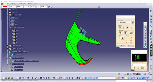
Above mentioned figures shows draft analysis performed on class-A surface at a draft angle of 3 degrees
TOOLING AXIS, DRAFT ANALYSIS ON CLASS A SURFACE OF ARM WRIST:
Similar procedure as above is maintained for remaining parts of door trim also. First I have extracted one of the surface patch, which is suitable for creating the main tooling axis. Then created the point on the extracted patch using point type as ‘On surface’ option. Once the point is created on the surface, the next step is to draw the dummy tooling axis. After creation of dummy tooling axis, with the help of axis system insertion at generated point, using intersect command two lines were generated across class A surface as shown in figure. These two lines generated were bisected using the created point and thus main tooling axis is created as shown in figure. Also for more details, refer to the figures mentioned below.
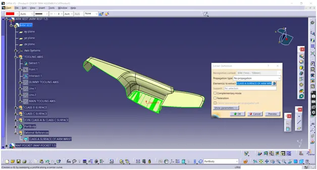
Figure represents the extraction of flat surface of lower substrate with no propagation for generating point on the surface
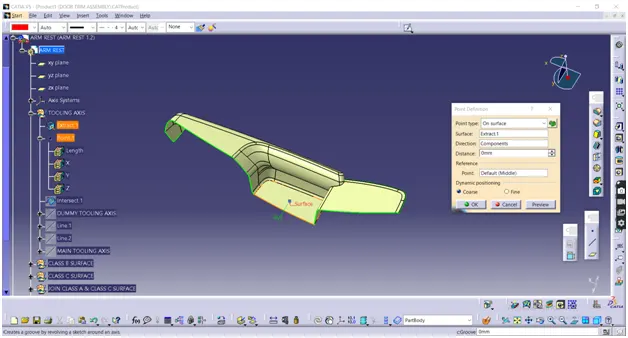
Above figures shows that, point generated on the appropriate patch using extract and point on surface options
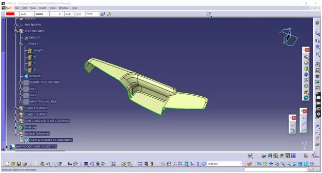
Using intersect option for bisecting the dummy tooling axis
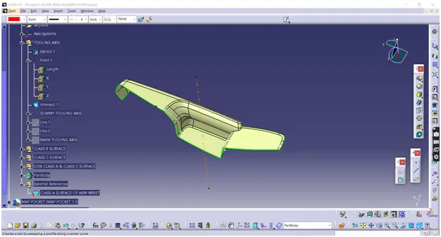
Using intersect option for bisecting the dummy tooling axis
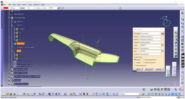
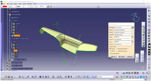
Dummy tooling axis is bisected to generate main tooling axis
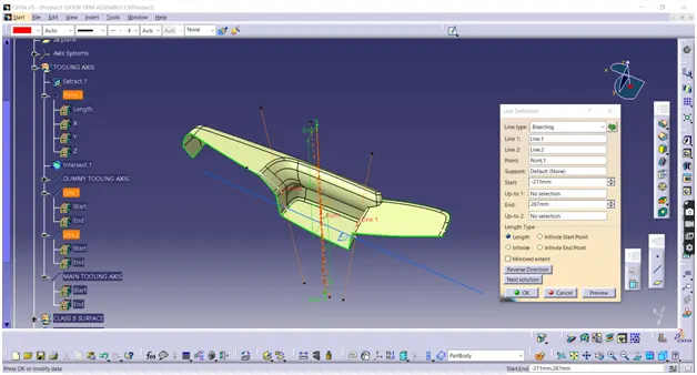
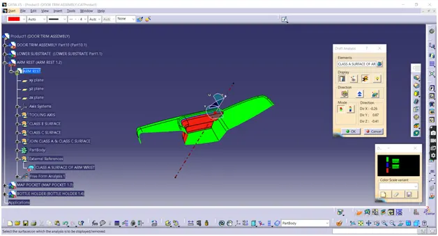
Now, once main tooling axis is generated, draft analysis is made on given class - A surface with 3 degree draft. And it was observed that given class - A surface is well designed for 3 degree draft.
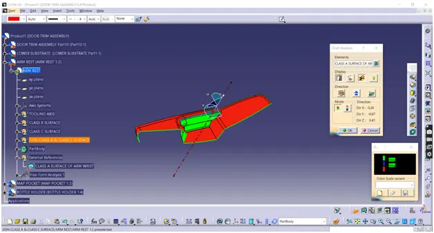
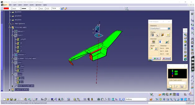
Figure shows draft analysis performed on class-A surface at a draft angle of 3 degrees
TOOLING AXIS, DRAFT ANALYSIS ON CLASS A SURFACE OF MAP POCKET:
Similar procedure as above is maintained for remaining parts of door trim also. First I have extracted one of the surface patch, which is suitable for creating the main tooling axis. Then created the point on the extracted patch using point type as ‘On surface’ option. Once the point is created on the surface, the next step is to draw the dummy tooling axis. After creation of dummy tooling axis, with the help of axis system insertion at generated point, using intersect command two lines were generated across class A surface as shown in figure. These two lines generated were bisected using the created point and thus main tooling axis is created as shown in figure. Also for more details, refer to the figures mentioned below.
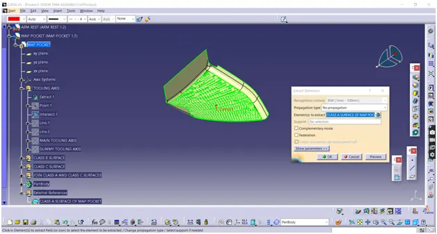
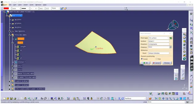
Above figures shows that, point generated on the appropriate patch using extract and point on surface options
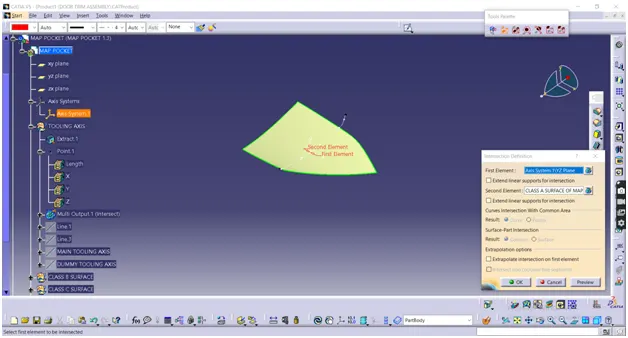
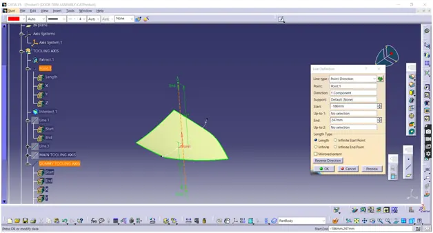
Using intersect option for bisecting the dummy tooling axis
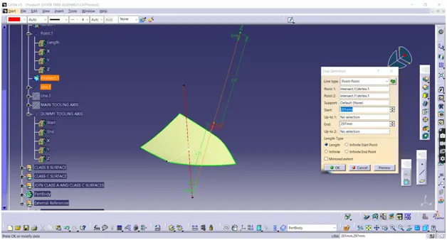
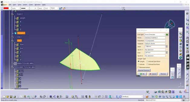
Dummy tooling axis is bisected to generate main tooling axis
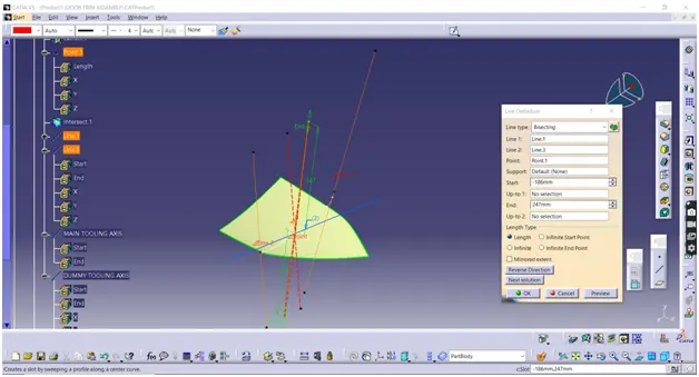
Dummy tooling axis is bisected to generate main tooling axis
Now, once main tooling axis is generated, draft analysis is made on given class - A surface with 3 degree draft. And it was observed that given class - A surface is well designed for 3 degree draft.
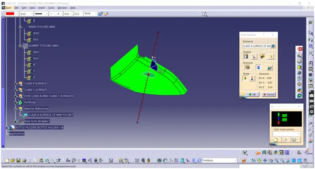
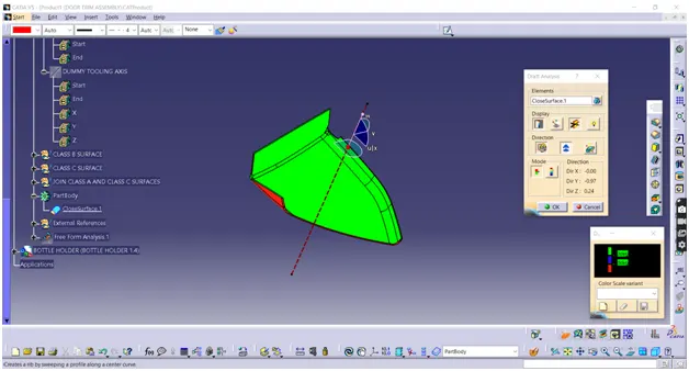
Figure shows draft analysis performed on class-A surface at a draft angle of 3 degrees
TOOLING AXIS, DRAFT ANALYSIS ON CLASS A SURFACE OF BOTTLE HOLDER:
Similar procedure as above is maintained for remaining parts of door trim also. First I have extracted one of the surface patch, which is suitable for creating the main tooling axis. Then created the point on the extracted patch using point type as ‘On surface’ option. Once the point is created on the surface, the next step is to draw the dummy tooling axis. After creation of dummy tooling axis, with the help of axis system insertion at generated point, using intersect command two lines were generated across class A surface as shown in figure. These two lines generated were bisected using the created point and thus main tooling axis is created as shown in figure. Also for more details, refer to the figures mentioned below.
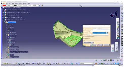
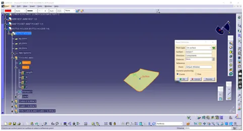
Above figures shows that, point generated on the appropriate patch using extract and point on surface options
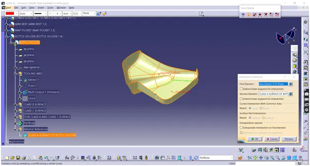
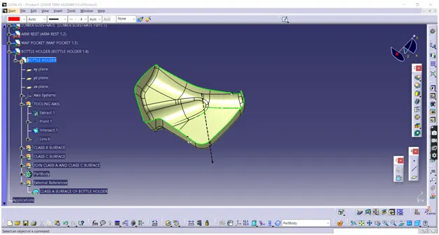
Using intersect option for bisecting the dummy tooling axis
Now, once main tooling axis is generated, draft analysis is made on given class - A surface with 3 degree draft. And it was observed that given class - A surface is well designed for 3 degree draft.
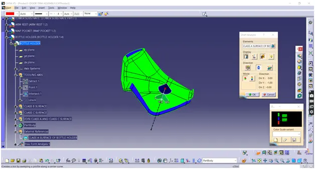
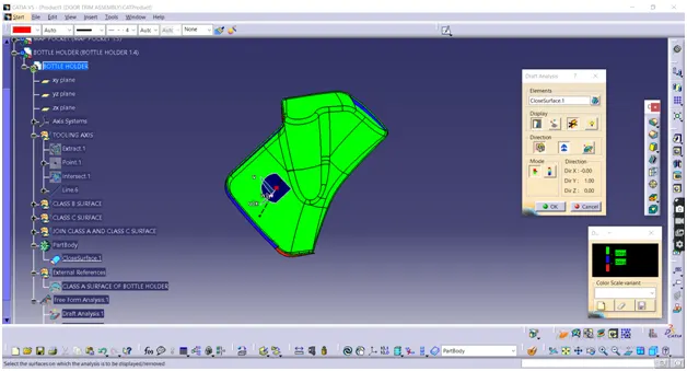
Figure shows draft analysis performed on class-A surface at a draft angle of 3 degrees
DRAFT PRODUCED ON CLASS - C SURFACE USING SWEEP:
Using class A surface, class C surface is generated with the help of sweep. Out of maximum boundaries of the given part, some of the boundaries of class A is selected and using sweep option, the angle of draft is given 3 degrees tending towards outward by selecting the option ‘with draft direction’. Also remaining boundaries were given sweep at an angle of 90 degrees by selecting the option ‘with reference surface’. This sweeping process is performed for all the given components of door trim, such as, lower substrate, arm rest, map pocket and bottle holder. Thus finally, after trim using closed surface option components were thickened and placed in appropriate part body
DRAFT ANALYSIS ON DOG HOUSE:
After creating the appropriate sketch or outline of doghouse, it has to be swept in a draft direction at a given angle of 1.5 degrees in inward direction to create a draft, as shown in figure mentioned below.
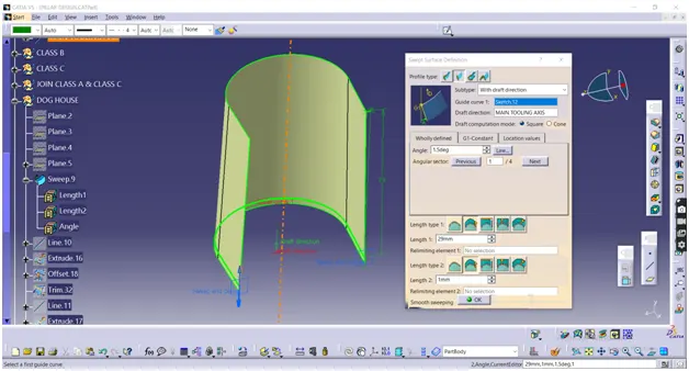
Also using draft command, on the stiffener, 0.5 degree draft is given. This can be understood by looking into the following figure mentioned.
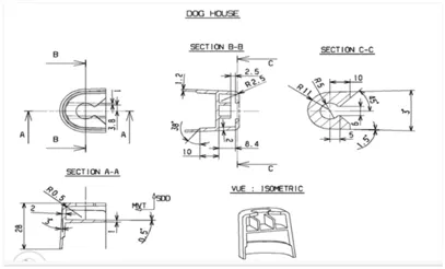
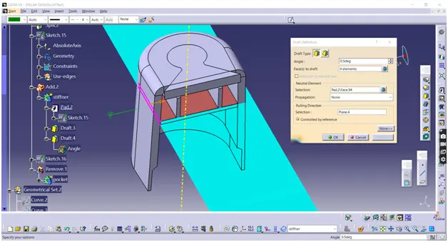
The base with cyan colour represent as stiffener on which 0.5 degree draft is applied
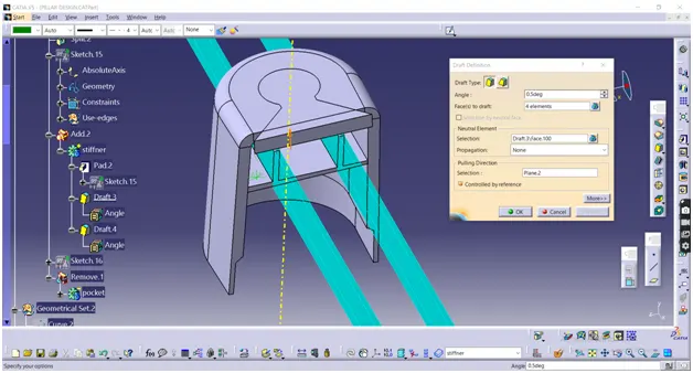
0.5 degree draft is applied to the walls of the stiffener
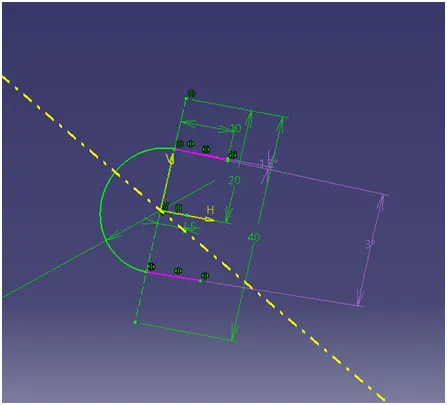
Figure shows the pink coloured sketch, in which, the draft angle is mentioned about 3 degrees according to the given figure in the challenge, therefore draft angle is adjusted to 3 degrees as per given instructions
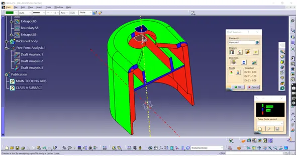
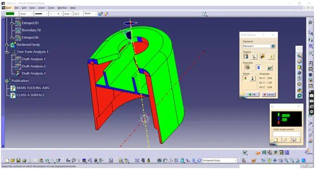
The above figures mentioned shows that, the draft angle of 1.45 degrees is performed on dog house by selecting the main tooling axis as the draft direction
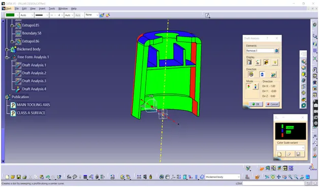
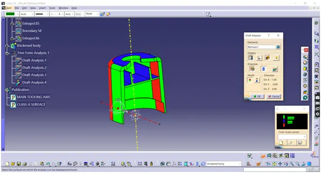
The above two figures shows the dog house where, inner walls are selected to perform draft analysis at an angle of 1.45 degrees using side core axis
Thus, separately for dog houses also draft analysis is made. First draft analysis done with respect to main tooling axis of lower substrate, for outside boundaries of dog house. Another draft analysis has done with respect to side core axis of dog house, for inner side boundaries of dog house. Thus according to the design parameters of dog house, it was observed that the draft angle of 1.45 degrees is well suitable and also the designed dog house met the required draft angle as shown in above figure.
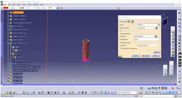
Figure shows 0.5 draft is giving to the inside and outside walls of heat stake
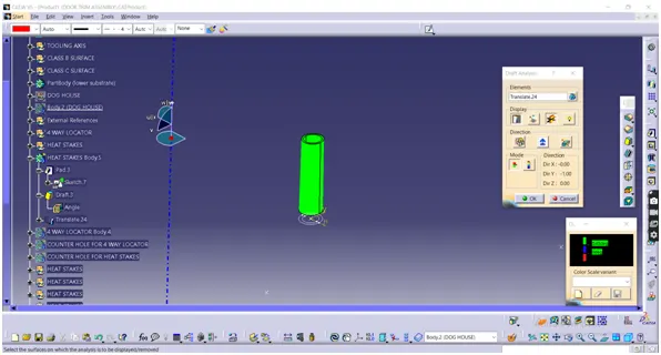
Figure shows 0.45 draft analysis is performed using lower substrate main tooling axis
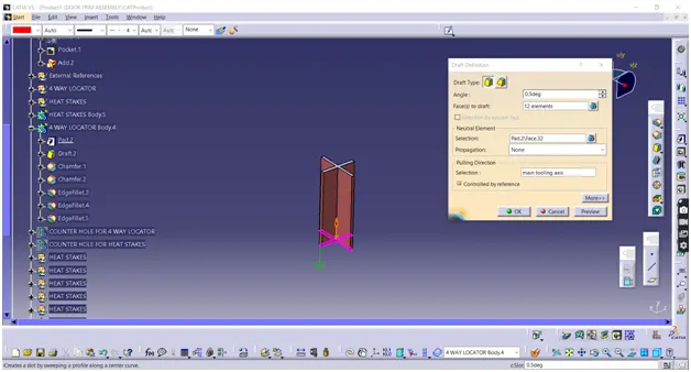
Figure shows 0.5 draft is giving to the inside and outside walls of 4 way locators
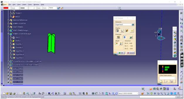
Figure shows 0.45 draft analysis is performed using lower substrate main tooling axis
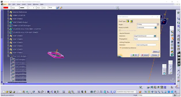
Figure shows 0.5 draft is giving to the inside and outside walls of counter hole made for 4 way locators
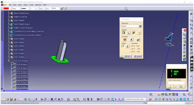
Figure shows 0.45 draft analysis is performed using lower substrate main tooling axis
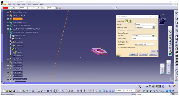
Figure shows 0.5 draft is giving to the inside and outside walls of counter hole made for heat stake
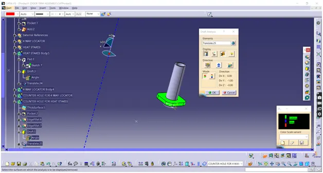
Figure shows 0.45 draft analysis is performed using lower substrate main tooling axis
The above figures mentioned, depicts that draft analysis made on locators and heat stake, as the draft analysis have done here at 0.45 degrees as per design rules with respect to main tooling axis. Here for locator inside face and outside faces, the draft angle is given about 0.5 degrees.
Finally, after translation of heat stakes, draft analysis is made on door trim, heat stakes and 4 way locators, with an angle of 0.45 degrees draft, and observed that the surface on which locators and heat stakes mounted on given points and surface is successfully turned into green. Here also draft analysis is performed same like the draft analysis performed for class A surface, except that final closed surface assembled with heat stakes and locators, door trim were performed draft analysis at 0.45 degrees instead of 3 degree draft.
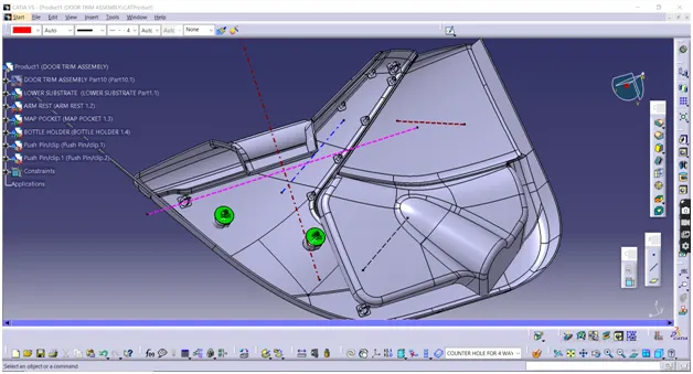
Thus, above figure is attached to represent a final project on door trim’s essential parts such as lower substrate, arm rest, bottle holder and map pocket
Also bush pins were assembled on the top of the dog house, please look into it.
Thanking you,