Week 12- Final project
WEEK 12 FINAL PROJECT
AIM – Development of door trim panel using catia V5 with given class A surface along with master section. Also create the engineering features for attachment of parts.
OBJECTIVE – Create thickened part using master section for reference.
Create the mounting features as per design guidelines in the industry and with master
Section.
Apply material details.
Draft analysis and tooling analysis.
Creation of parting lines and check tooling feasibility.
INTRODUCTION –
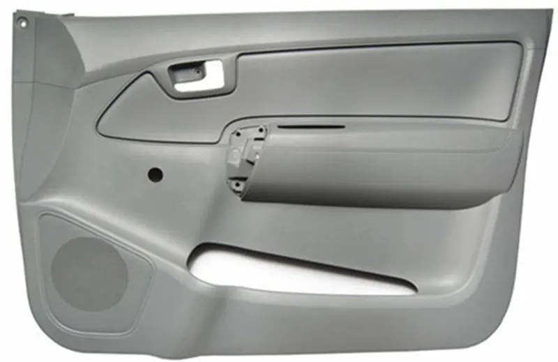
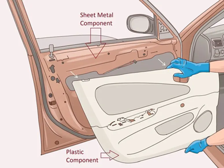
The door panel is interface between the interior of the car and the inner workings component of the door panel. Normally the door panel is divided in parts for easy designing like arm rest, bottle holder, map pocket, lower substrate. In the door panel it has lot of mechanism for speakers, bottle holding space, door locking system, buttons for electronic control.
METHODS –
TOOLING AXIS CREATION –
Tooling axis defines the close and open direction of core and cavity. By tooling axis we check that the part and the components are easily manufacturable and we can check the quality of part, also we can give some draft angle for easily remove of core and cavity.
There are some steps used to create the tooling axis.
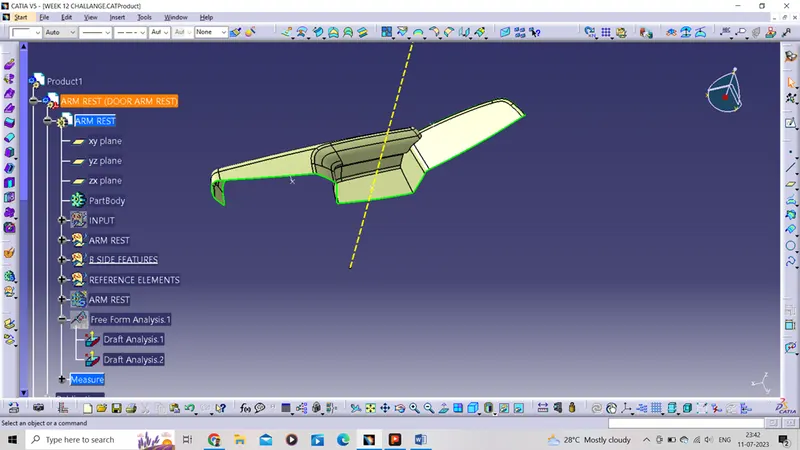
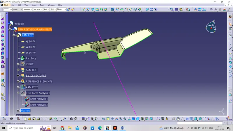
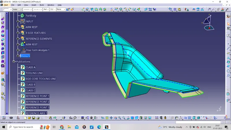
STEP 1 ARM REST – First of all I extract a surface using extract command and create a point using on surface method after I created a line using point and direction method and named it as tooling line. After that I created the another line using same method but this time I choose the direction as y component instead of z component and named it as side tooling axis.
Main tooling line is used for class a and solid part draft angle checking and the side tooling axis used for b side engineering features.
MAIN TOOLING AXIS (TOOLING LINE)-
SIDE TOOLING AXIS –
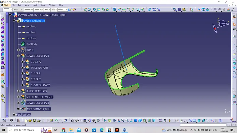
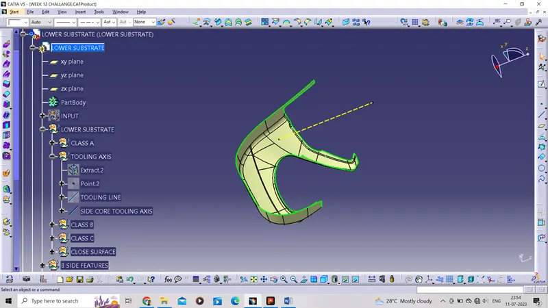
STEP 2 LOWER SUBSTRATE – First of all I extracted a surface from class a and created point using on surface method and created a line using point and direction method after that named it as tooling line. After that I created another line with same method changing the direction, after that I named it as side tooling line.
TOOLING LINE
SIDE TOOLING LINE
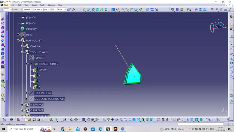
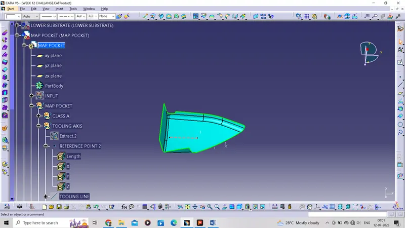
Step 3 MAP POCKET - I extracted a surface from class a and created point using on surface method and also created a line using point and direction method after that named it as tooling line. After that I created another line with same method changing the direction, after that I named it as side tooling line.
TOOLING LINE
SIDE TOOLING LINE
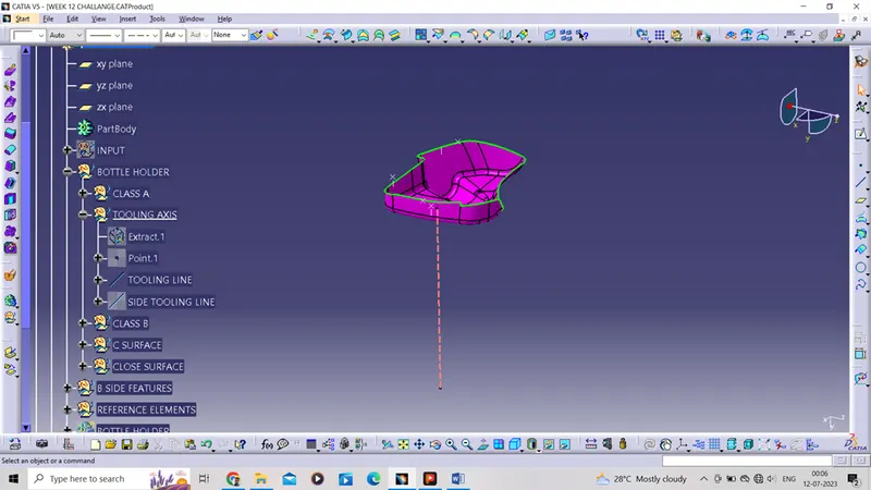
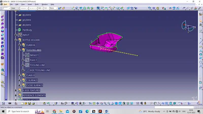
STEP 4 BOTTLE HOLDER - First of all I extract a surface using extract command and create a point using on surface method after I created a line using point and direction method and named it as tooling line. After that I created the another line using same method but this time I choose the direction as y component instead of z component and named it as side tooling axis.
TOOLING LINE
SIDE TOOLING LINE
CLASS B SURFACE CREATION –
We create the b surface using class a surface. In the b surface all engineering features are attached. Usually I can say that the b surface is the surface witch connect the engineering features to the door panel.
There are some steps used to create the tooling axis.
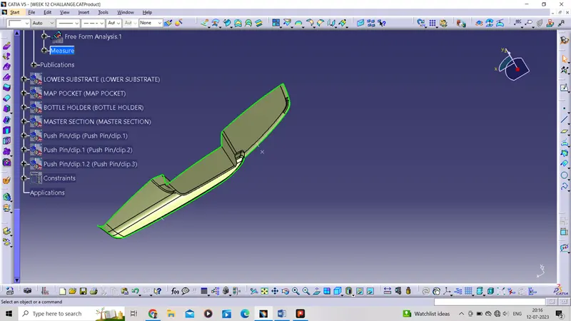
STEP 1 ARM REST – First of all I offset the surface.746 by 2.5mm (which is the thickness of component) from master section, there some surface were not offset so I extract them by using no propagation. After that I extrapolate the extract 5. After that I take the split command and for element to cut I choose extract 4 and cutting element as extract 3 and split. And extrapolate the extract 3 also extrapolate the split 2 after I extrapolate the extract 4. After that I extract a surface and untrim. After I offset it by 2.5mm and split the offset 2 by cutting element as extrapolate 5 edge 7&8. After that I extrapolate the extrapolate 5. After I extrapolate the extrapolate 7 by 7mm and trimmed the extrapolate 6 with extrapolate 8. After that I extrapolate the trim2 by 7mm. after that I trimmed the extrapolate 9 with split 3. After that I extrapolate the trim3 face 13&14 with no propagation and created a boundary. After that I extrapolate the extract 7 by 7mm and extrapolate the extract 8 by 7mm with curvature continuity and then trim the extrapolate 10 with extrapolate 11. After that I took the multi section command and fill the gap between two surfaces and join the multi section surface with trim4. After that I extrapolate the join 3 by 2mm with curvature continuity and named it as class b.
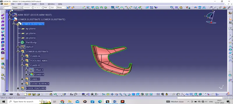
STEP 2 LOWER SUBSTRATE – In this step I offset the class a by 2.5mm, extrapolate it by 0.75mm with curvature continuity and then I named it class b.
STEP 3 MAP POCKET - In this step I offset the class a by 2.5mm. After that I got a surface but there were some missing surface so I created a boundary and created a spline then using multi section command get a surface then I join it with offset 1. After that I took different-different boundary on each edges of map pocket and extrapolated it. At last I got a surface and named it as class b.
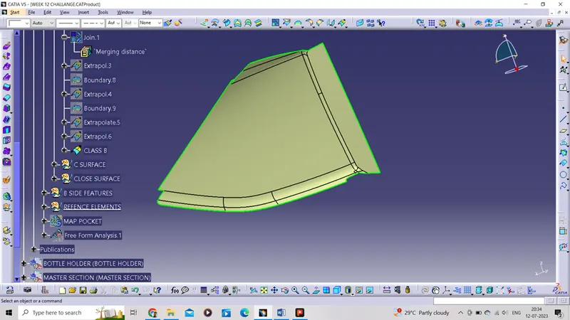
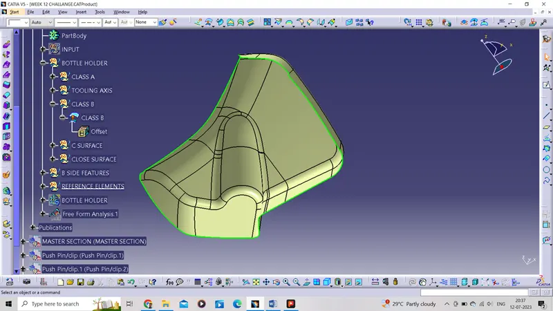
STEP 4 BOTTLE HOLDER – I offset the class a by 2.5mm and named it as class b.
CLASS C SURFACE CREATION –
Class c surface which connect the class b surface with class a surface.
There are some steps used to create the class c surface creation.
STEP 1 ARM REST - For creation of c surface majorly we use sweep command, so in this step I used the sweep command with line command with reference surface and pick the class a and gave the angle of 90 degree. Second time I pick the subtype as with draft direction and for draft direction I pick the tooling line and created the sweep surface. Third time I created the multi section surface because there were some gap between these two sweep surface .Now I follow the same method and created another four sweep surface. After that I took the multi section command and split command and created many surfaces between all sweep surface to connect each other and extrapolate the sweep 2 and split 4 and then I trim extrapolate 12&13. After that I join the sweep 1, multi section surface, trim 5, multi section surface 3 and split 5. At last I named it as class c.
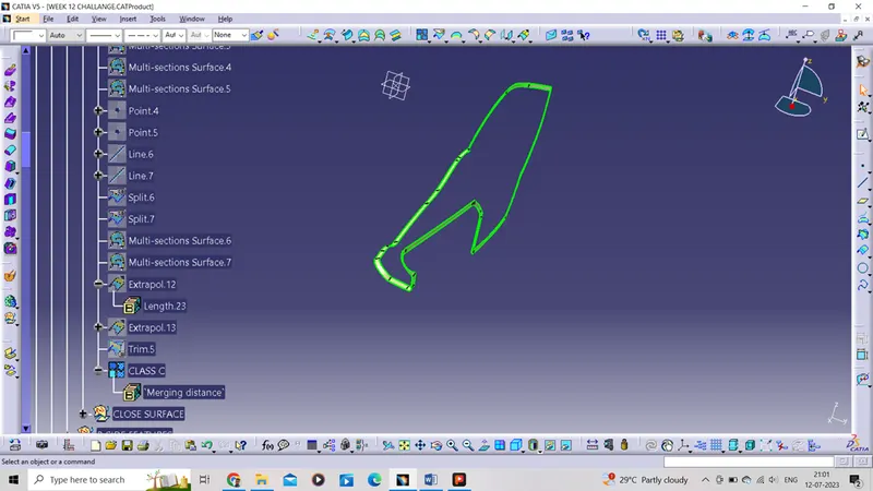
STEP 2 LOWER SUBSTRATE – Once again creation of c surface majorly I used the sweep command with line command subtype as with reference surface and pick the class A and gave the angle of 90 degree. I was created the whole sweep surface in five different- different parts same as first. After that I had done split operation and used multi section command to fill the gap between the sweep surfaces. After that I done the extrapolation of sweep surfaces and splits to make as proper intersecting surface. After that I trim the extrapolate 8,7,5,3&2 then I join the trim1 and multi section surface 1. At last I named it as class c.
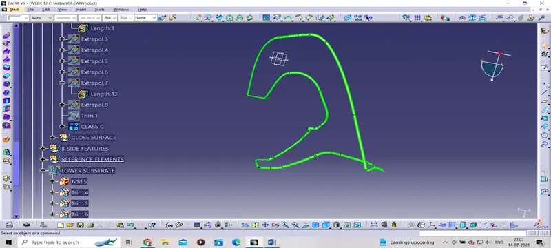
STEP 3 MAP POCKET - Creation of c surface I map pocket majorly I used the sweep command with line command subtype as with reference surface and pick the class A and gave the angle of 90 degree. For sweep 1 I used line command subtype as with draft direction and for direction I pick the tooling line and gave the angle value 3 degree. I was created the whole sweep surface in four different- different parts. After that I had done split operation and used multi section command to fill the gap between the sweep surfaces and extrapolate the split 2 and sweep 4. After that I trim the extrapolate 1&2 and join the trim1 with split 1&3 and multi section 2&3. At last I named it as class c.
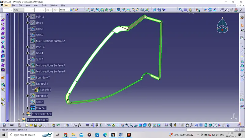
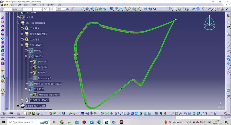
STEP 4 BOTTLE HOLDER – In bottle holder at first I pick the seep command in line type subtype as with reference surface and pick the class a and gave angle value as90 degree and with same method I create another sweep surface and after that I done the multi section operation to connect the sweep 1&2 then I join the sweep1, sweep 2 and multi section surface 2 and named it as class c.
CREATION OF FINAL COMPONENT –
In this step we connect c surface with class A and class B.
There are some steps used to create the class c surface creation.
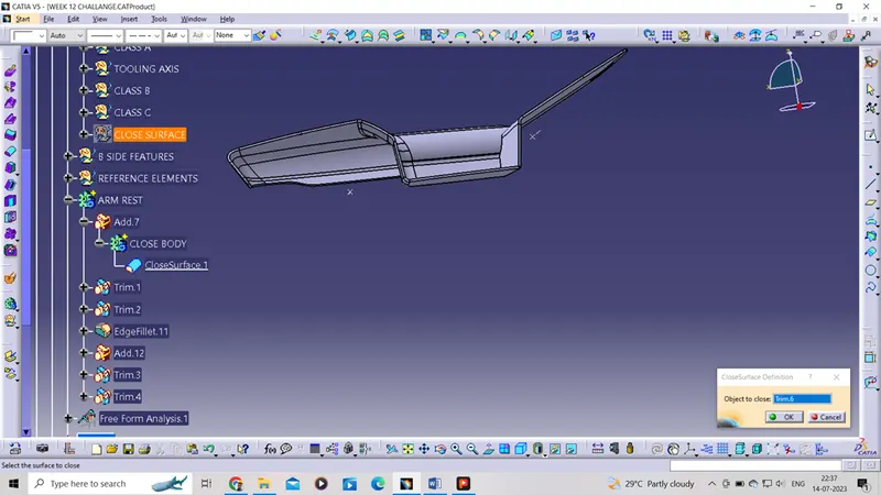
STEP 1 ARM REST – In this step I join the class a with class c then trim with class b then I got the close surface. After that I went to part design workbench and add a part body then pick the trim6 as object to close. At last I got close body of arm rest.
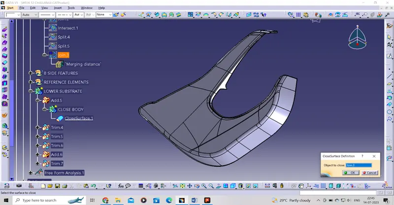
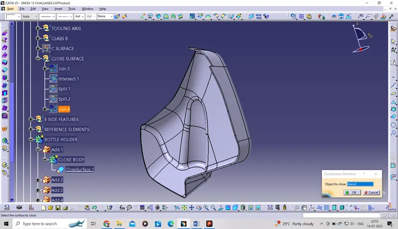
STEP 2 LOWER SUBSTRATE – In this scenario I used different method to create close surface. First of all I join the class a with class c then create a intersection first element as class c and secont element as class b. after that I split the class b with intersect1 and then split join 2 with intersect 1. After that I join the split 4 with split 5. Now I got the close surface then I moved to part design workbench and add a part body then pick the join 3 as object to close. At last I got close body of lower substrate.
STEP 3 MAP POCKET – In this scenario I used same method as second one at last with same method I created the close body of map pocket.
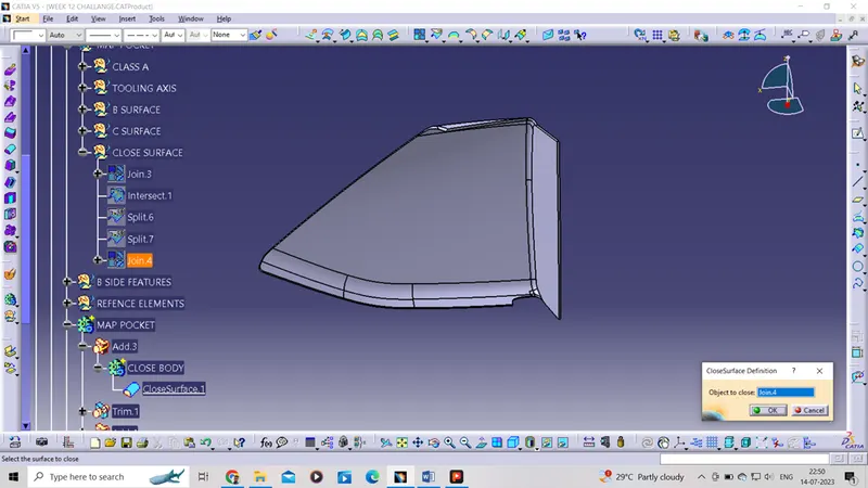
STEP 4 BOTTLE HOLDER – In this scenario I used same method as last one and created whole solid body of bottle holder.
CREATION OF ENGINEERING FEATURES –
There are following engineering features are used in door trim panel.
1 – DOG HOUSE
2 – HEAT STAKE
3 – SCREW BOSS
4 – FLANGE
5 – LOCATOR
6 - RIBS
STEP 1 DOG HOUSE AND RIBS –
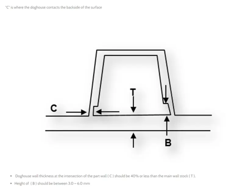
Dog house is an engineering feature which used to support other engineering features like as screw boss, locators, ribs etc.
I extract a surface from class a then create a point using on surface method and create a ZX plane on point. Then I create a sketch using positioned sketch.
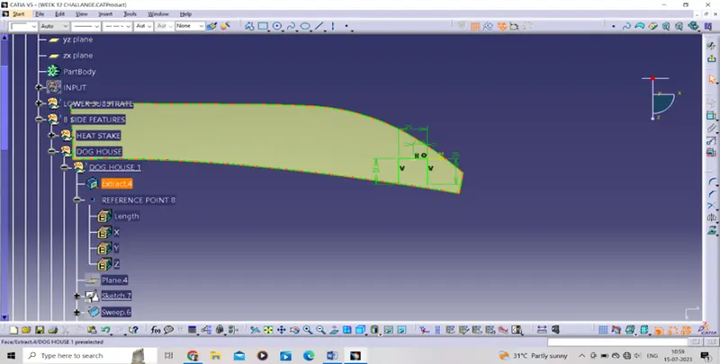
After that I create a sweep surface using line option subtype as with draft direction and for draft direction I picked the tooling line and gave the angle value 1.5 degree(this is the draft value of dog house) and pick arrow of inside also gave some length value according to law.
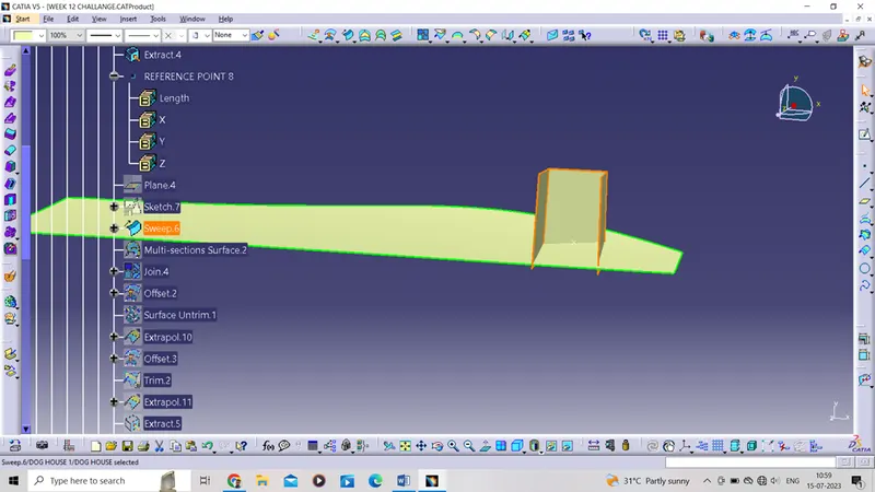
After that I use multi section option for fill the open upper area of sweep surface because there was not proper base surface of class a so I used it and join the sweep 6 with multi section surface 2.
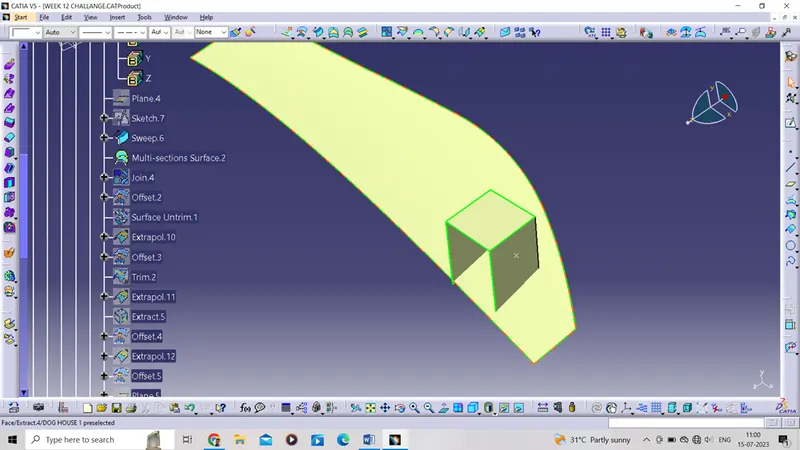
After that I offset the sweep 6 and untrim the extract 4 then extrapolate the surface untrim 1 also offset it by 4mm, then I trim the offset 2 and offset 3. Now I got the b&c area of dog house. After that I done some extrapolation and offset operation to make it fine.
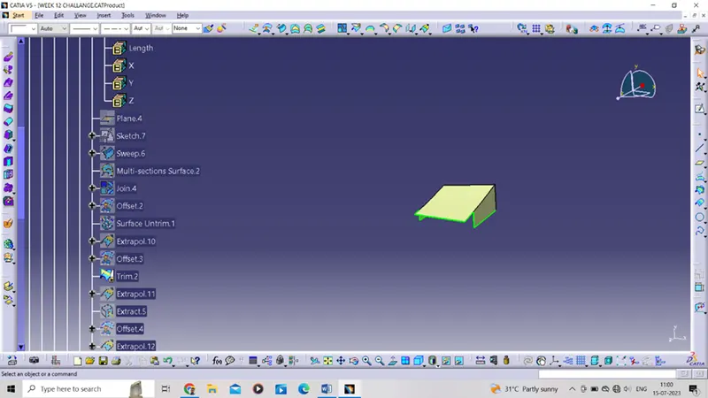
After that used two positioned sketch to create sketch for ribs and key hole for push pin clip.
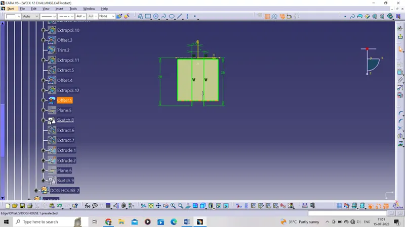
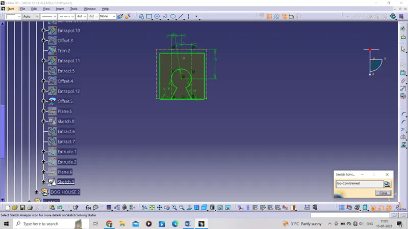
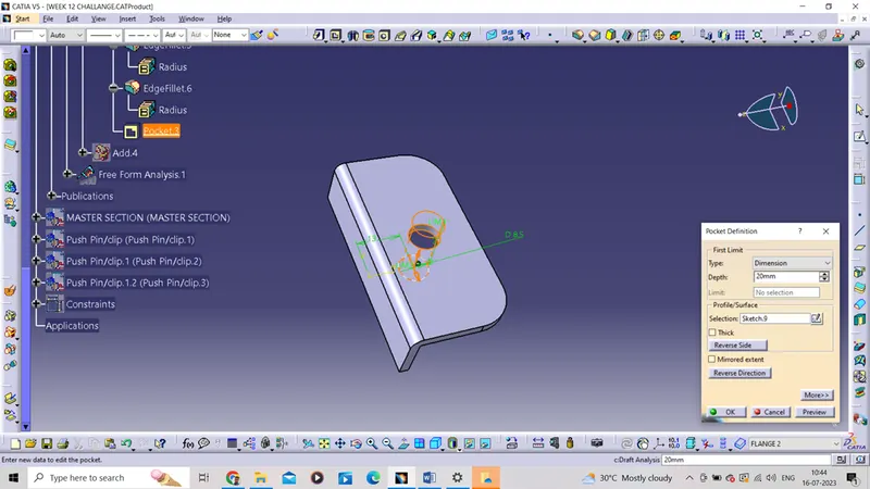
After that I went to part design work bench and add part body to create the solid body of dog house. At first I thickened the join 4 by 2mm and gave edge fillet and done split operation after that gave draft angle as 0.5 degree and then gave some edge fillets inner of dog house. After that I thickened the ribs and do some edge fillets and union trim with dog hose and and then I used pocket command and make a key hole on dog house using sketch 9. Thus I completed the dog house creation.
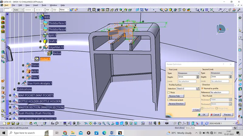
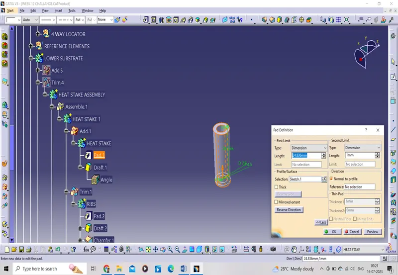
STEP 2 HEAT STAKE– Heat staking is a method of joining two or more parts, where at least one is made out of plastic. The bond is made by partially de-forming the plastic part to fix the other. Heat staking is the most efficient way to bond metal to plastic, and is commonly used in high volume/low cost applications in the automotive. We always make sure that gap between two heat stake minimum 50mm for better quality.
First of all I extract the curves given by master section then I use the split command and make perfect lines and pick a point through the lines and take a plane on it after that I make two sketches one for heat stake another one for ribs.
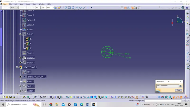
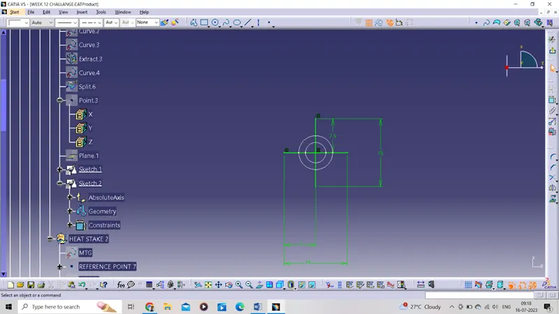
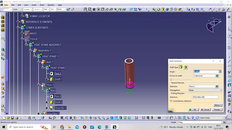
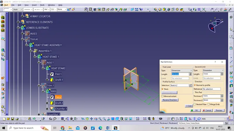
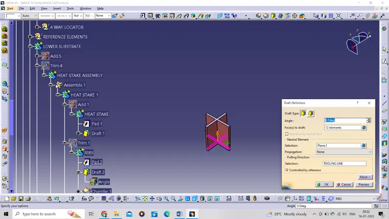
After that I went to part design work bench and add part body and pad the sketch 1 and gave draft of 0.5 degree pulling direction as tooling line. After that I add another part body and pad the sketch 2 selected the thick option and gave draft on it 0.5degree for pulling direction I picked the tolling line. After that I gave chamfer of 45 degree and then I join the ribs and heat stake. After that I gave some edge fillets.
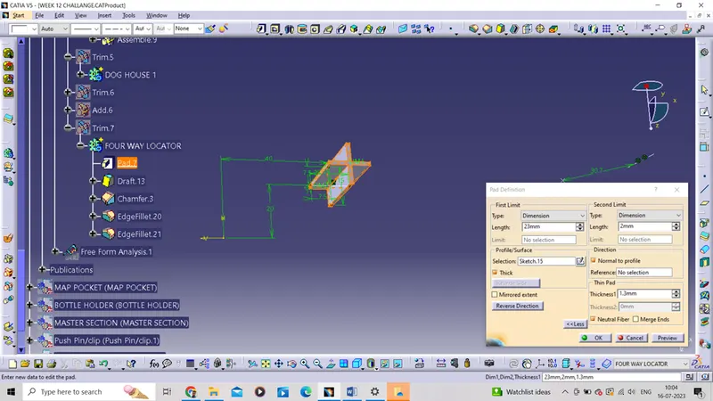
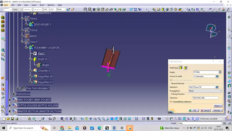
STEP 3 FOUR WAY LOCATOR – In this step I extract a surface and create a point using on surface method then convert it into coordinate. After that I create a ZX plane using parallel through point. After that I create a positioned sketch. After that I went to part design work bench and add a part body and pad and gave 0.5 degree draft for tooling direction pick the tooling line. After that I gave a chamfer of 45 degree and length of 3mm. after that I gave two edge fillet of 3mm and 0.25mm.
STEP 4 FLANGE – Flange is an engineering feature which used to connect minimum two different parts.
In this step I extract two different – different surfaces and create a point also make a YZ plane and create an inter section through the plane and extract 3. After that I created two positioned sketches as presented below.
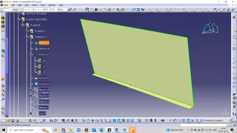
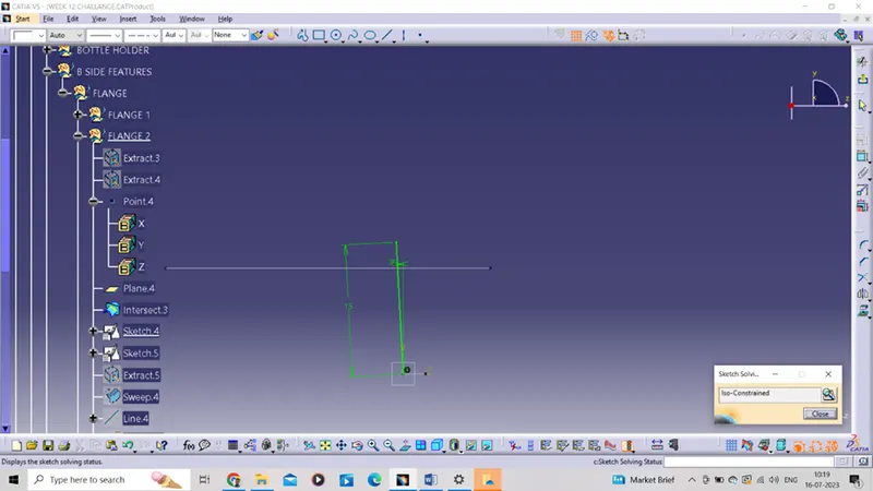
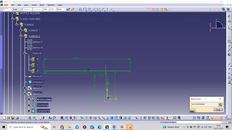
After that I extract the edge of extract 3 and create a sweep operation used subtype as wit reference surface and for guide curve pick the extract 5. After that I create a line using point to point method for point I picked the different-different edge point of sweep 4 and then extrude it. After that I trimmed the extrude 5 and sweep 4.
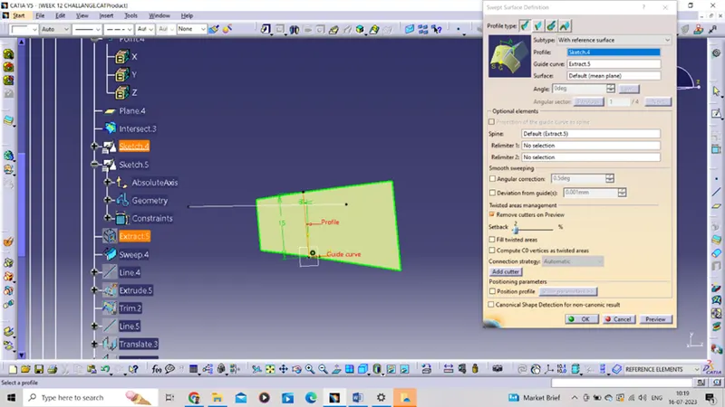
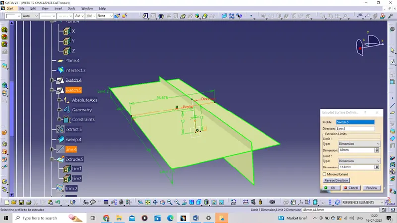
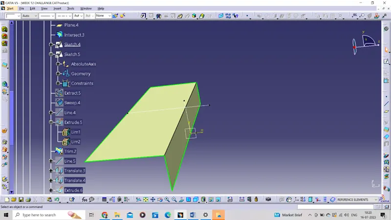
After that I create a line using normal to surface method and translate it two opposite direction then extrude them and create another positioned sketch.
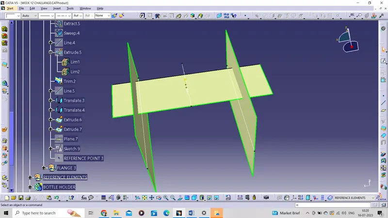
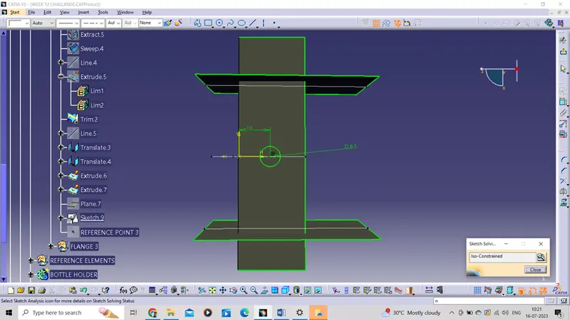
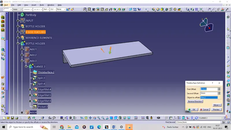
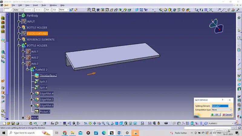
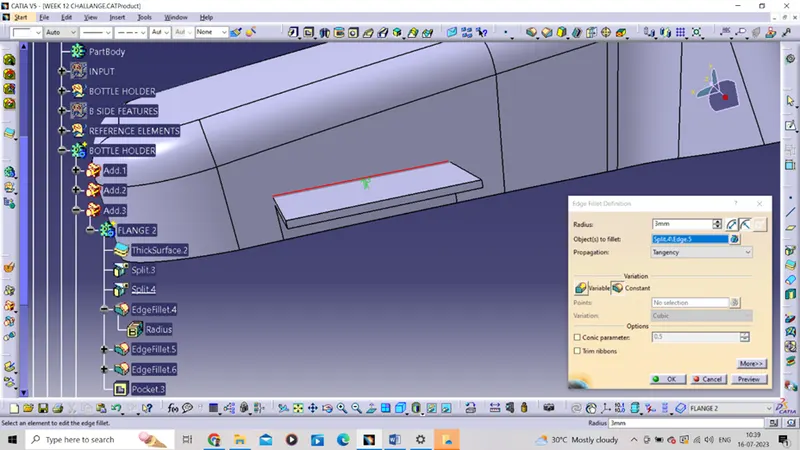
After that I went to part design workbench and add the part body and pad the trim 2 and split it using the extrude 6&7. After that I gave some edge fillets and at last I done the pocket operation using sketch 9.
Now I completed the flange creation.
DRAFT ANALYSIS –
1 – DRAFT ANALYSIS OF CLASS A,B &C
2 – DRAFT ANALYSIS OF SOLID BODY WITH ENGINEERING FEATURES
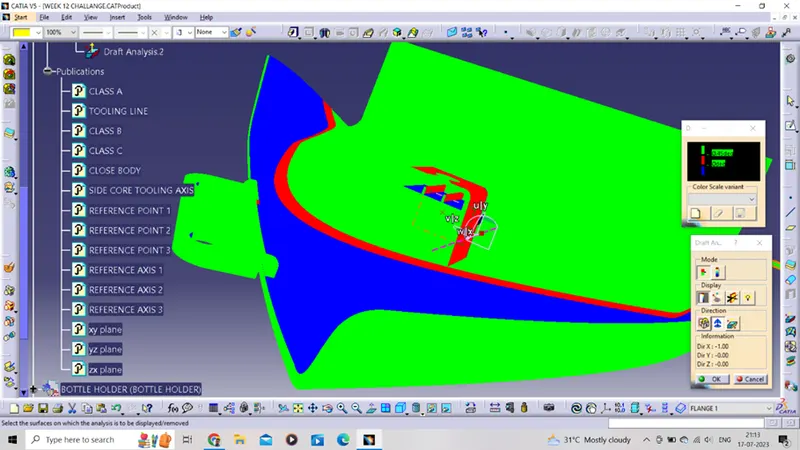
DRAFT ANALYSIS OF CLASS A,B&C –we perform the draft analysis to the class a surface to ensure that we have good quality of surface to make Class B and C surface to achieve the same kind of quality surface.
1 – DRAFT ANALYSIS OF CLASS A,B &C-
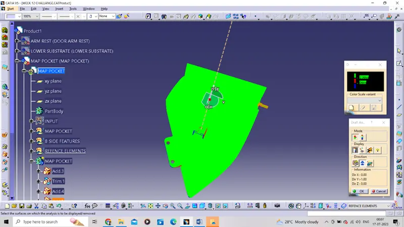
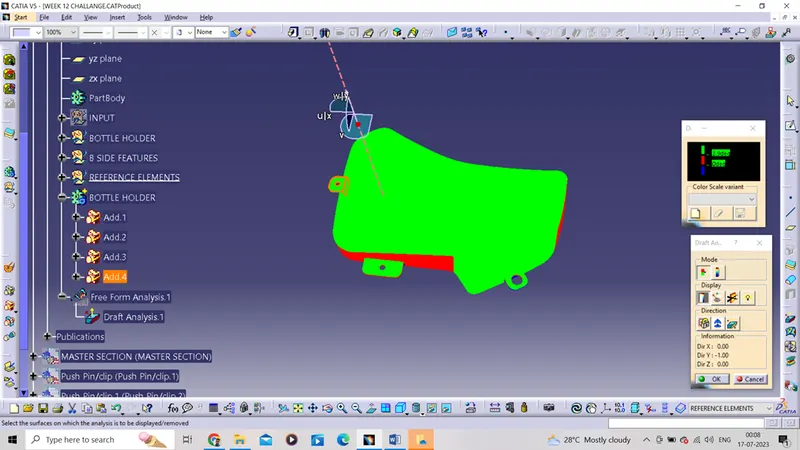
First of all I put the surface in shading with material mode. Then I set the compass on the main tooling axis to get the direction of core and cavity moving direction. Once compass is locked in the axis, directly click on the surface it will appear quality of draft surface whether, it is pass or failed. Here I gave the draft value 2.9 degree for green colour and 0 for red colour. Hence I achieved green colour on top surface. So it accepts the draft angle for the surface that’s mean my tooling line is right.
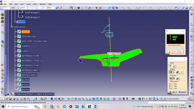
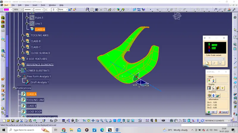
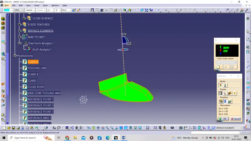
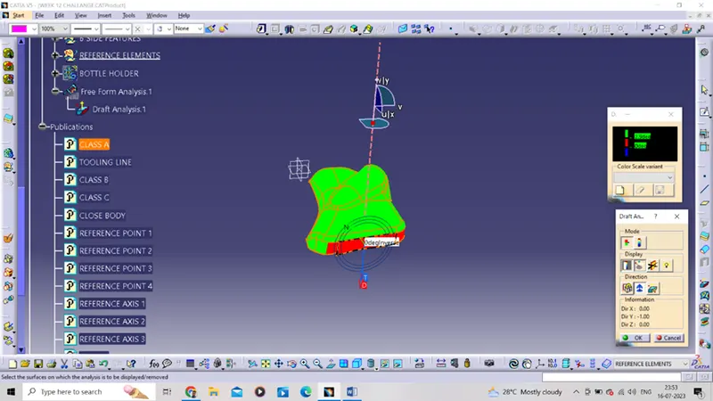
There are some surface are not clearing the tooling line showing 0 degree so I confirm from technical department they told that it is mistake by them.
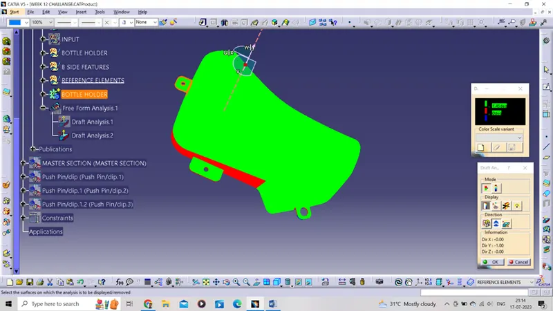
2 – DRAFT ANALYSIS OF SOLID BODY WITH ENGINEERING FEATURES – 1 SOLID BODY =
First I set the compass on the main tooling line to get the direction of core and cavity moves. Here I gave the draft value 2.9 degree for green colour and 0 for red colour.
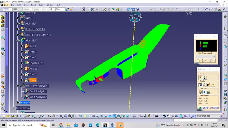
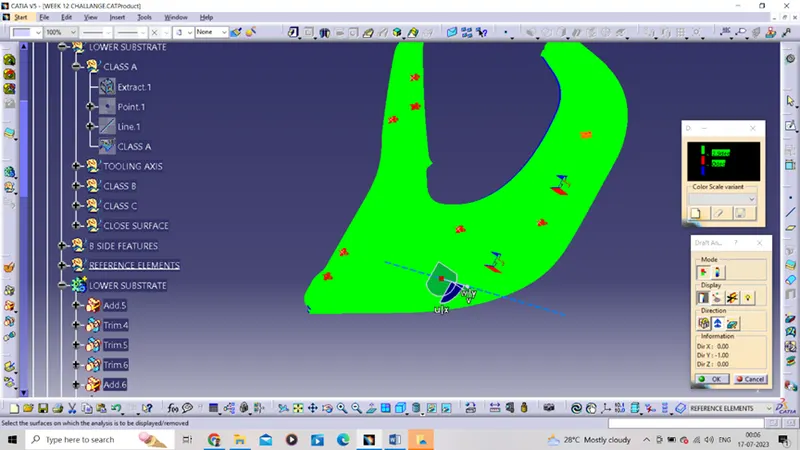
2 ENGINEERING FEATURES –
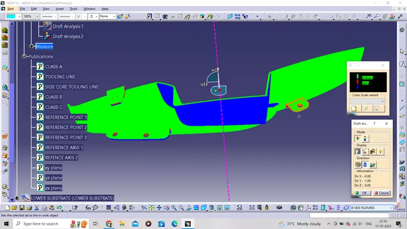
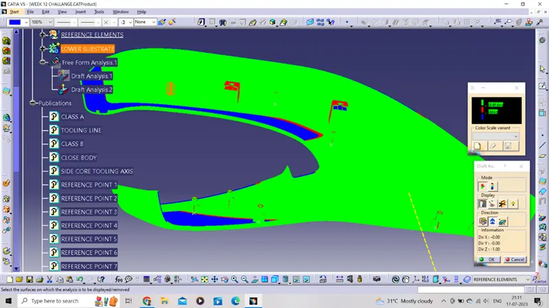
First I set the compass on the side tooling line but dog house and screw boss outer surface always analyzed by main tooling line. Here I gave the draft value 0.5degree for green colour and 0 for red colour. For main tooling line gave 1.45 degree as green colour.
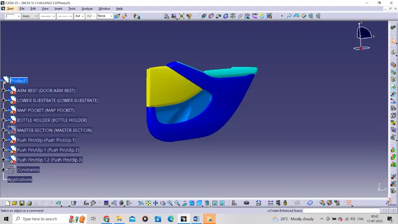
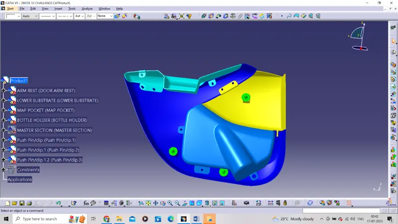
ASSEMBLED PICTURE OF DOOR TRIM PANEL –
CREATION OF PARTING LINE AND PARTING SURAFACE –
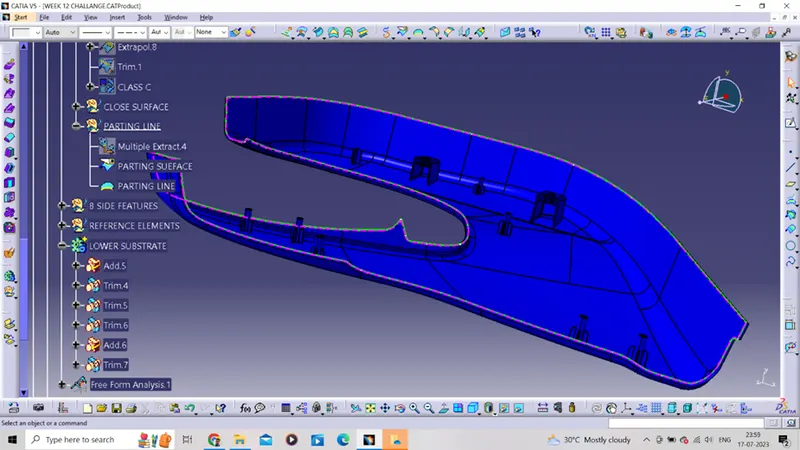
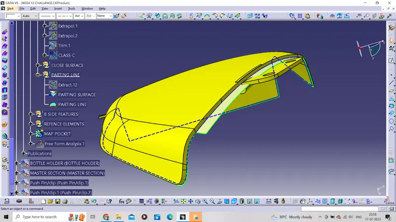
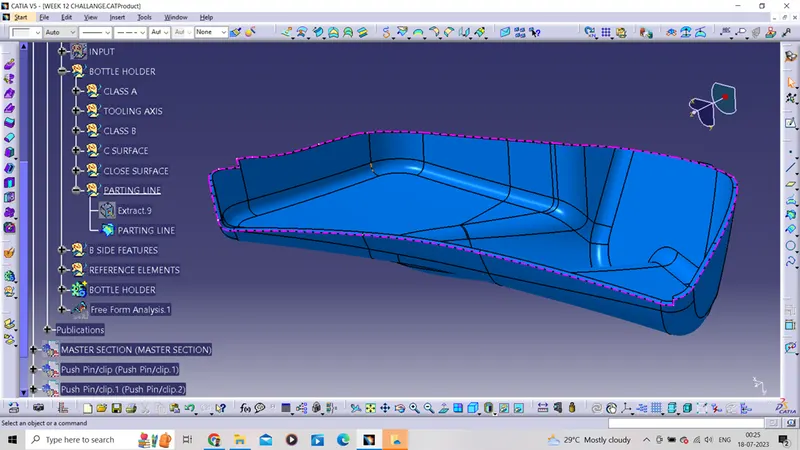
Parting line is a line which differentiate the core and cavity. Along the parting line outer surface called parting surface.
Here I created the parting line in two method.
- First of all I extracted the b surface with point continuity and then extrapolate it. After that I split the class b cutting element as class c then I got a surface, the boundary of inner surface is parting line.
- In this method I extracted the b surface with point continuity and then I create an intersection between extracted surface and class c surface. This intersection is going to my parting line.
CONCLUSION –
Creation of the door trim panel is designed using the given class a surface as the input. Class B and C surface created with the help of Class A surface. By using the given master section attachment features Heat stakes, Flanges, Dog House are created using the design rules. The draft analysis has been performed to analysis the draft of the component to manufacture easily applying draft to the surface by 2.9 degree and 0.5 degree to the attachment features. With all data and report I can conclude that draft analysis is very important to design any plastic component and it may also highlights defect areas.