Week 12- Final project
Final Project
Aim :-
- To develop a Door Trim panel CAD model by considering the inputs given (ie., Class A surfaces,Master Sections) as like in OEM and Tier 1companies.
- Develop an attachment strategy for the complete Door Panel work by creating the B side features as per dedign guidelines.
- Use Pushpin (given) with Dog House for attaching the Trim with the BiW part and Heat Stakes for part to part attachment.
PROCEDURE:
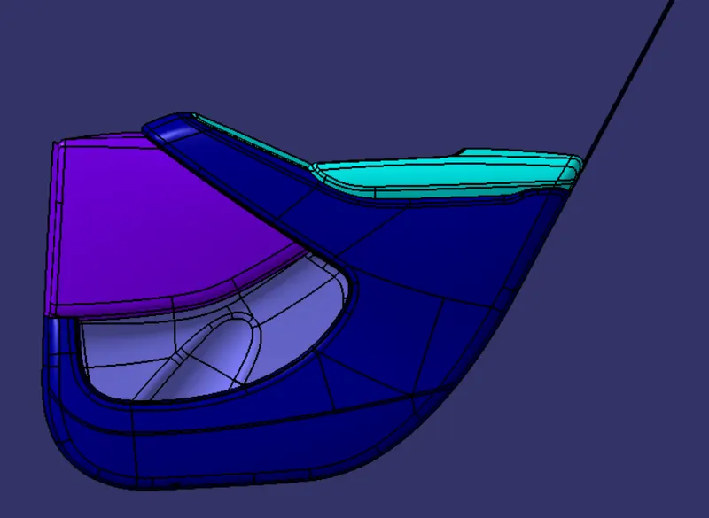
Class A surface of a door panel received from the styling team. In the automotive industry dedicated team is allocated to develop class A surface using sketches followed by ideation. Class A surface is the first input given to the plastic designer.
Methodology :-
Creation of Lower Substrate :-
- Top-Down approach of Assembly is followed for developing the Door Trim panel.
- DFMA (Design for Manufacturing and Assembly) are main criterias should be kept in mind.
- Five Part Files are segregated inside one Product File starting with the Master Sections file and then proceeding on with the other Class A surface files given.
- Now,starting with the surface quality inspection of the given Class A of the Lower Substrate,which comes out fine.
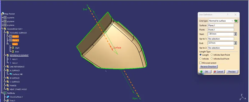
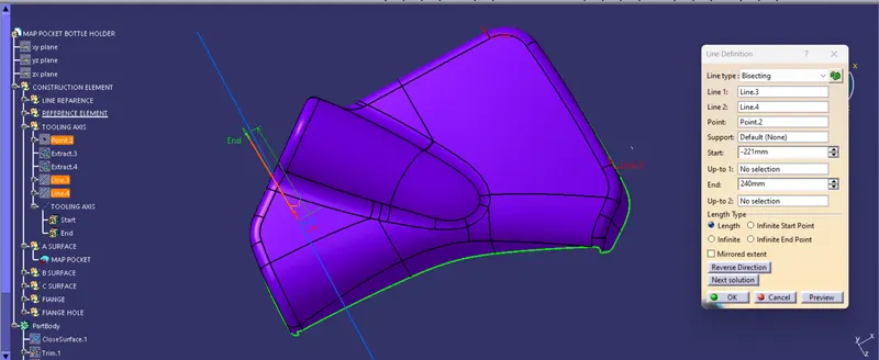
- Creating the Tooling Axis for the Lower Substrate using Point-Direction option of the Line creation by checking the compass direction,and then checking the Tooling feasilbilty by performing Draft Analysis.
-
Creating a tooling axis in class A surface:
- The direction in which the mould open and closes is the tooling axis.
- Check the connectivity of the surface and ensure there will be no gap between the surfaces and then define the tooling axis.
- While creating a tooling axis give the tooling axis on a flat length surface or the surface which have a hole on it.
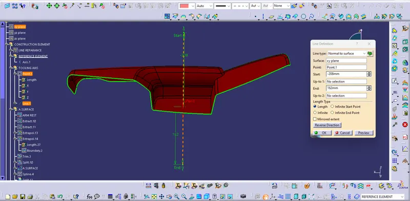
- Create a point on the surface where we are going to create the dummy tooling axis and using line command crate an axis. If there is a circle or flat length surface which is recommend
Arm rest : -
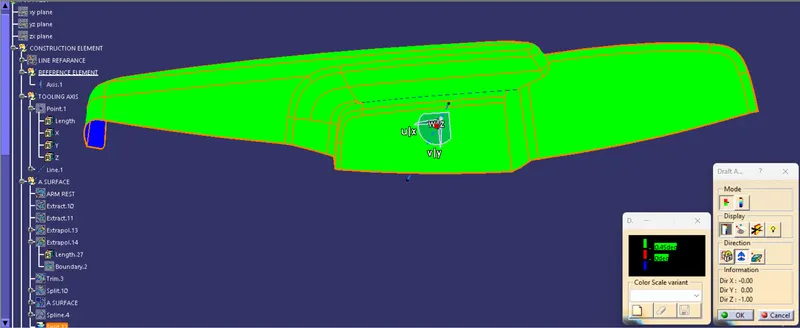
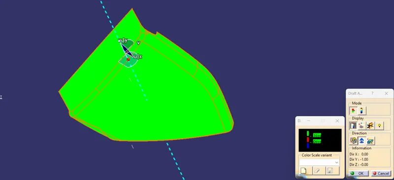
Designers of plastic parts and mould tooling manufacturers can use the Draft Analysis tool to check the correct application of draft to the faces of their part. With draft analysis, you can verify draft angles, examine angle changes within a face, as well as locate parting lines, injection, and ejection surfaces in parts.
For this case as no hole is concerned, so we will try to consider the perpendicular axis of that dented curved surface, for creating the tooling axis. So we will analyse perpendicular plane.
Creation of tooling axis
The line has been created using the line command. The point-direction option is used to create the main tooling axis in the z-direction.
Draft Analysis on Class A :-
• Creation of Class B surface
Class B surface has been created by offsetting of class A surface. Offsetting has been done using the offset command. Class A surface is offset with a 2.5 mm distance. Surfaces that were not offsetting were formed using Spline and Fill command.
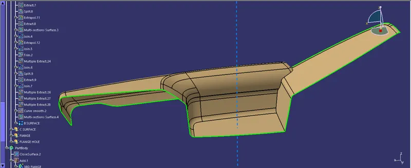
• Creation of Class C surface
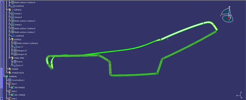
Using the Multiple extract commands, boundaries of class A surface were extracted. Class C surface joins class A and class B surfaces. It is created using the sweep command. Inputs for the sweep command were extracted boundary, class-A surface, angle value, and length of the sweep. Due to surface irregularities, it was not possible to create a single sweep. Hence, several sweeps and multisection were created, and finally, they joined together to create a class C surface.
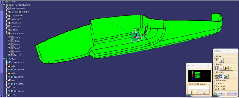
Draft Analysis (Solid Body) :-
Upper Map Pocket -
Using same method we will create tooling axis for rest of the parts.
Draft Analysis on Class A :-
Class B is created by offseting Improved Class A by 2.5 mm as per the master section.
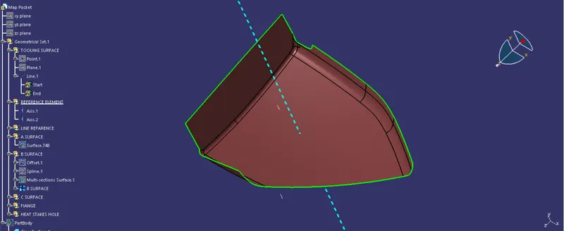
Class C is created by sweeping Improved Class A Surface and it has been trimed with Class B Surface
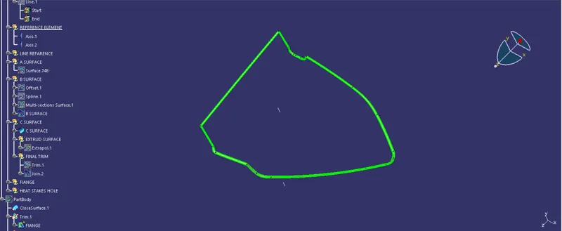
Draft Analysis (Solid Body) :-
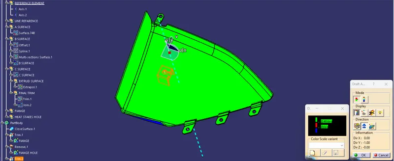
- Due to improper Class A surfaces,majority of the Class C aren’t getting cleared in the Main Tooling Axis and for that we need to inform the Stylist for Class A modifications.
- Few surfaces are clearing the Main Tooling and the regions are shown below.
Bottle Holder :-
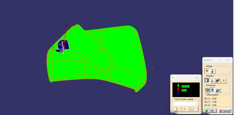
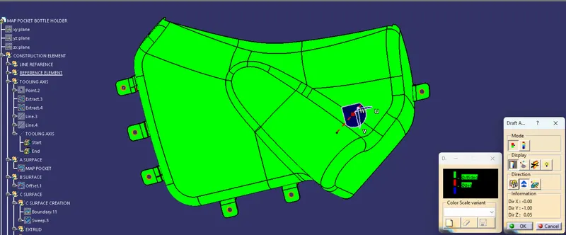
Upon performing the Draft Analysis on Class A,we found out that few faces aren’t clearing minimum required draft of 3 degrees,and for that we need to inform the Class A Stylist for improvements.
Draft Analysis on Class A :-
Class B is created by offseting Improved Class A by 2.5 mm as per the master section.
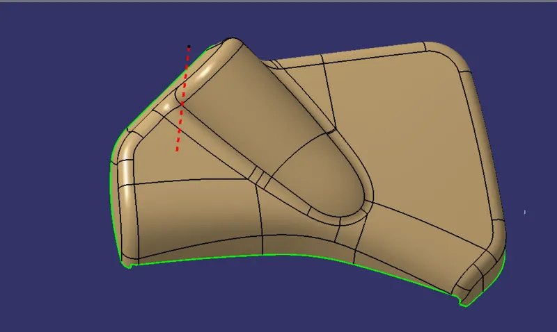
Class C is created by sweeping Improved Class A Surface and it has been trimed with Class B Surface
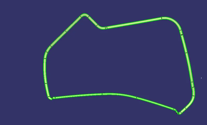
Draft Analysis (Solid Body) :-
Lower Substrate:A-
Class A Surface was givin is cheke and found out it is perfectly closed boundries,no further action to be taken.
Main Tooling Axis is created in such way to provide drafting.
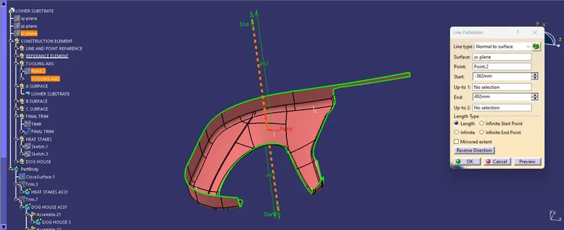
Draft Analysis on Class A :-
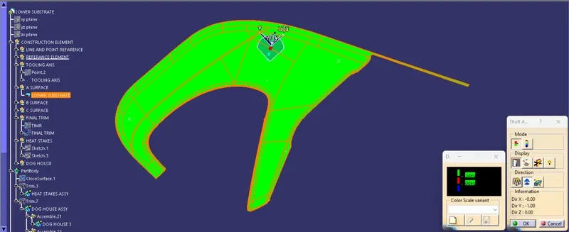
Class B is created by offseting Improved Class A by 2.5 mm as per the master section.
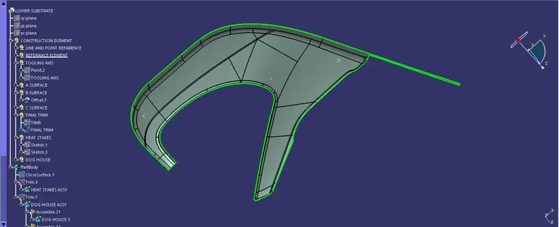
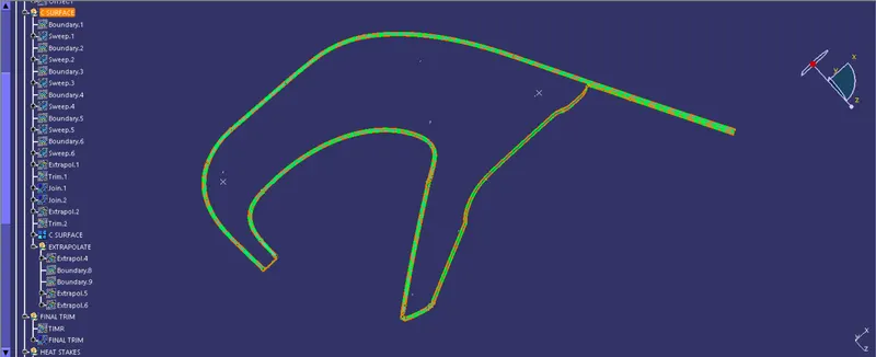
Class C is created by sweeping Improved Class A Surface and it has been trimed with Class B Surface
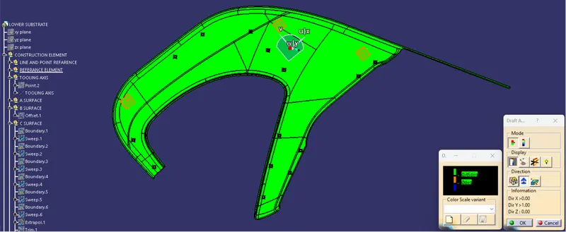
Draft Analysis (Solid Body) :-
DOG HOUSE:
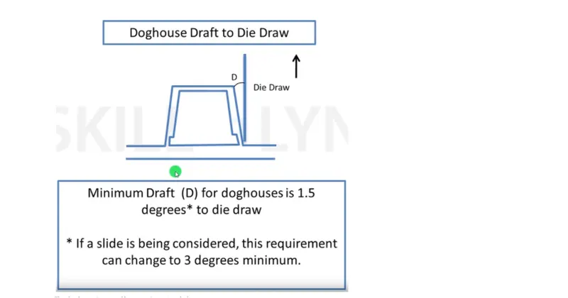
Dog house is an engineering feature used in the plastic trim design. Doghouses are used as supporting features. Sometimes other engineering features like snaps; locators, etc. are mounded on them to increase their strength. Dog houses are subjected to draft analysis to prevent breakage of the component during ejection from the mold cavity. Dog house and other engineering components are built on B-surface.
Here the dog house is required for lower substrate only. So for creating the dog house I have extracted the base surface of the lower substrate
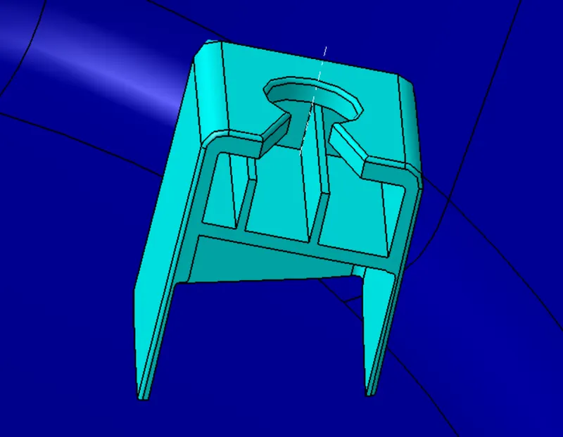
For this purpose, I have just offset the base of the lower substrate to a height of 4mm the value could be anything between 3-6mm and then I have extracted the inside portion of the dog house.
Then I have extrapolated the inside portion that extracted and trimmed it with the base.
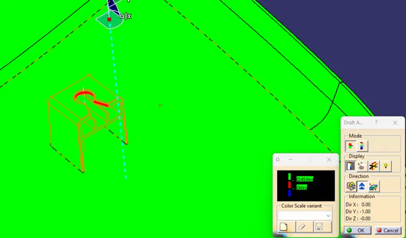
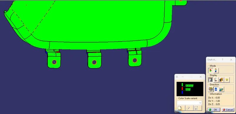
Draft Analysis :-
Creation of Heat Stakes :-
- The basic purpose behind the creation of Heat Stakes is for arresting the degree of freedom of the assembly along the tooling axis direction.
- Heat stakes are designed by referring the Master Sections given and by following the Tooling Axis direction of the Lower Substrate.
- Supporting Ribs are provided on the Heat Stakes for strengthening them
- The distance kept between Heat Stakes are 50-60 mm so that the hot plate doesn’t get in contact with another heat stake when plastic welding is being carried out.
- Heat Stakes (child) and Flanges (parent) are plastic welded by melting the protruding heat stake onto the flange.
- Height of the heat stake = 25 mm (by referring the Master Sections).
- Thickness = 3 mm
- Inner and Outer Dia = 4mm and 7 mm (by Master Section).
- Length of supporting ribs = 15 mm
- Thickness of ribs = 1 mm (40 % of the component’s thickness)
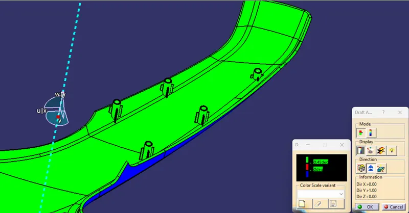
- Draft (heat stakes and ribs) = 0.5 deg (with the Component’s/Main Tooling Axis)
- Tip thickness ≥ 0.75 mm
All the Ribs design rules are followed.
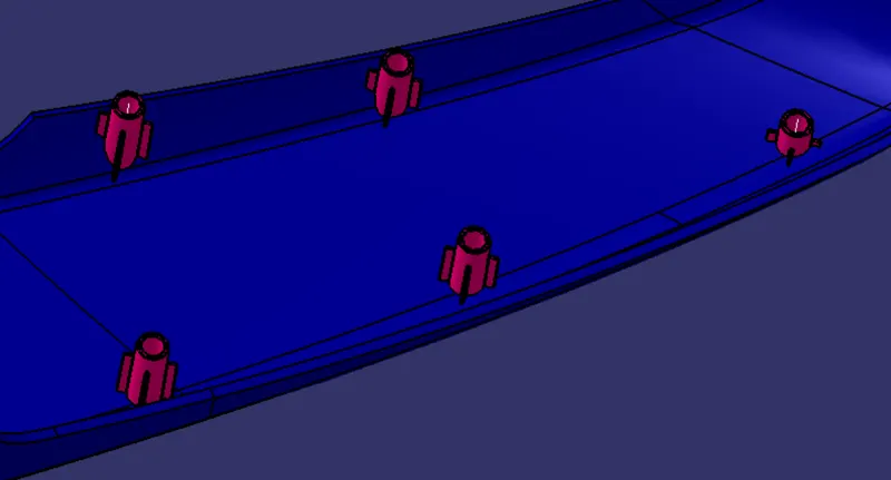
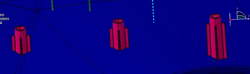
Heat Stakes and Ribs:
The use of heat stakes is to attach two plastic components permanently. A total of 13 heat stakes were placed at different locations on the lower substrate. One heat has been created onto the door armrest part which will be attached to the upper substrate. Following the muster section, the outer diameter of the heat stake is 7.5 mm and the inner diameter is 4.5 mm. Necessary slots are made onto other parts where heat stakes will attach together. Draft of 0.5 degrees has been given to all the heat stakes. All the heat stakes have ribs attached to them. All the ribs have 1mm thickness and 0.5 degrees of the draft. The length of the ribs is 14 x 14 mm.
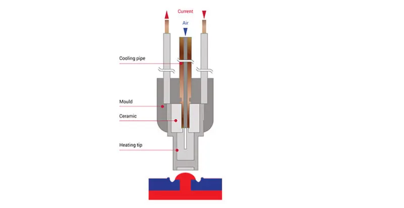
Heat staking also known as thermoplastic staking is the process of joining two dissimilar materials together. In heat staking, we use local heating and cooling to raise the temperature of plastic components and allow plastic reforming to be carried out. This reforming can be used in a wide variety of applications.
Draft Analysis of Heat Stakes : -
FLANGES :
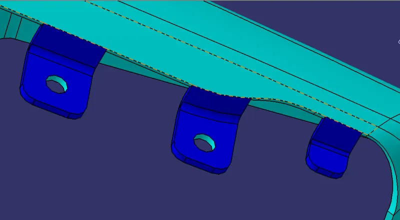
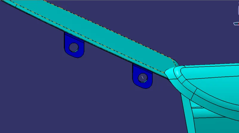
Flanges are the elements that are needed to join different components together. So here I have to make flanges on the door Armrest, Map pocket and Bottle holder. Following the master section, given as the input basically the measurements and location of the flange. I have created the flanges. First I have created the flange on the Arm rest. For creating the flanges I have taken extraction of the curve and made a point on that curve then created one plane on that point followed by creating a sketch on that plane taking the point created as the origin. The sketch is shown below:
FLANGES of Arm rest : -
FLANGES of Upper Map Pocket :-
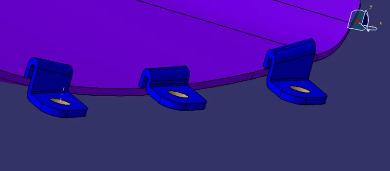
FLANGES of Bottle Holder :-
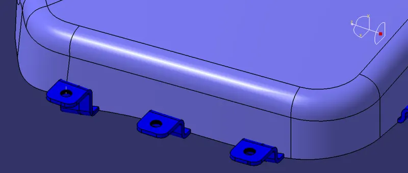
Draft Analysis :-
Minimum draft of 0.5 degrees is given wrt Side Tooling of the Arm Rest.Fillets are given as per the Master Section provided by neglecting the leatherette cover thickness.Minimum fillet of 0.25 mm are given at rest of the areas.
Draft Analysis Arm rest : -
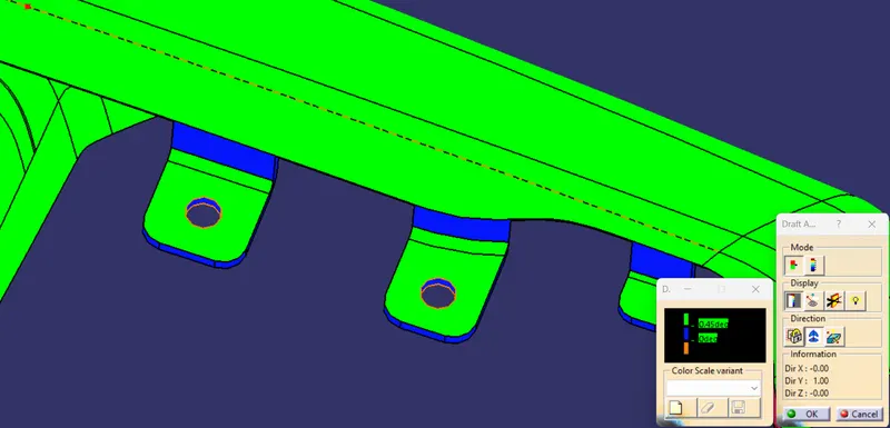
Draft Analysis Upper Map Pocket -
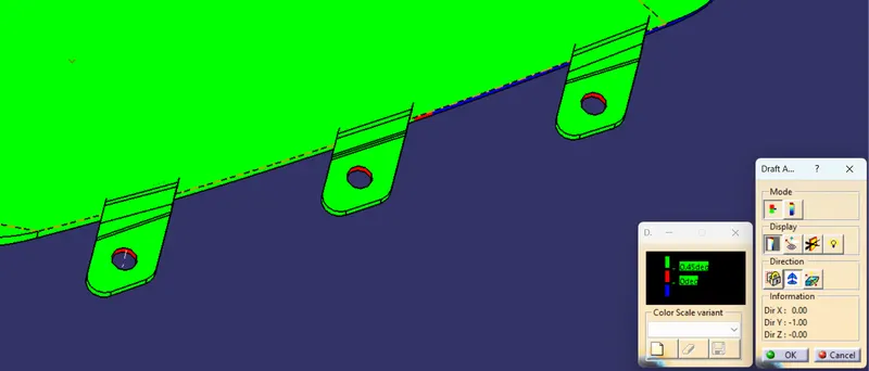
Draft Analysis Bottle Holder :-
Push Pin:
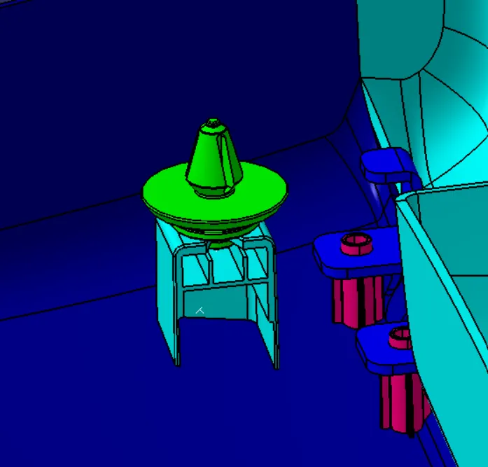
As I have created fore Dog Houses for this part assembly, i need to inport fore Push pins.
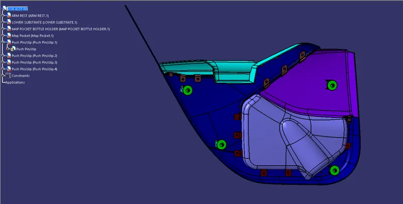
Both are assembled correctly as shown:
Push pins-Push pins are used for joining one component to another. These are basically attached to the dog houte For creating the push pins I have taken the following reference basically the measurements
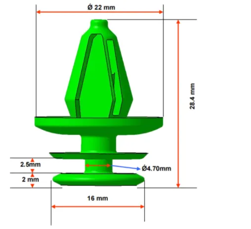
Then I have made the cut out on the dog house for inserting the pin. For the cut out I have made one sketch on the top surface of the dog house and extruded it.
Then I have split the extrude from the dog house to get the cut-out. The cut out for the puse
Final Assembly :-
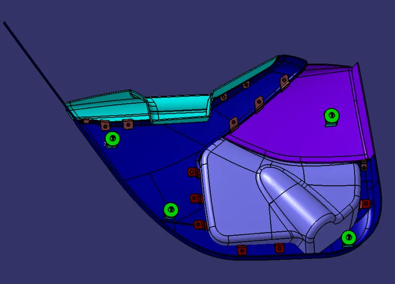
The below image shows the entire assembly of the Door Trim Panel complete work after attaching the Push Pins given.