Week 12- Final project
FINAL PROJECT
DOOR PANEL
TOOLING AXIS CREATION
- for the tooling axis of the arm rest i had selected a point on the surface of the most posible tooling direction
- and created a perpendicular line with point direction method
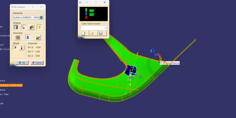
- check the tooling axis is correct or not by doing initial draft analysis
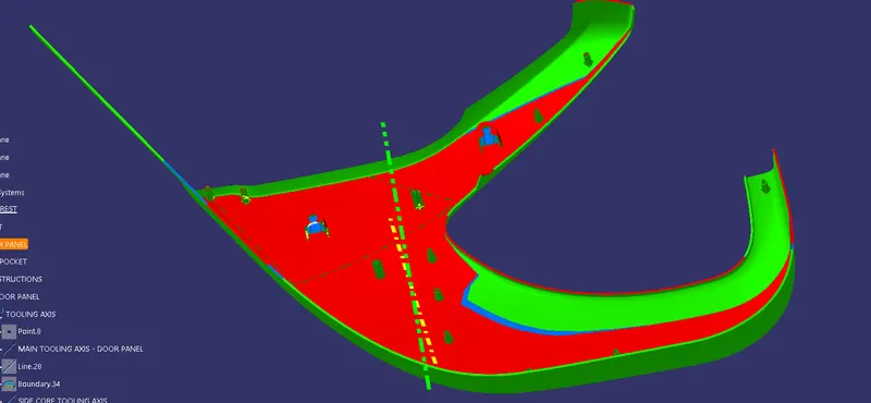
- and add a parellel line to the tooling a surface that will be our side core tooling axis
- check those are correct tooling directions with the help of draft analysis
CLASS B SURFACE CREATION
- check for the thickness in master section given
- the given thickness is 2.5mm
- then offset the class A surface to required position

CLASS C SURFACE
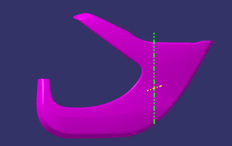
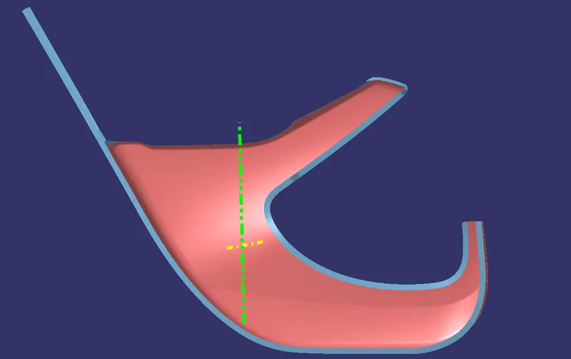
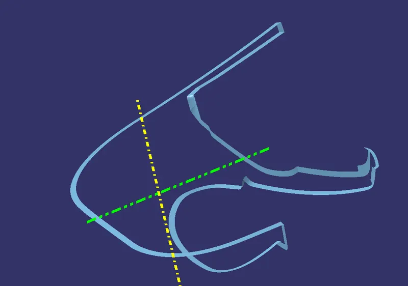
- from the class a surface findout the boundaries that can be sweeped with draft direction and others with reference surface
- divide those with the help of perpendicular end and parellel end
- then sweep accordingly
- if there is any complicated curves or retractions create a spline from the end points of nearest sweep and support as outer ends
- then extract the other 3 boundaries
- do multisection surfaces with the sweep side extract as profile and guide curve as spline and boundary
- if that doesnt work join every 4 boundaries and fill that space
- then join those with nearest sweeps with a max deviation of .1mm
- do this procedure for any complicated surfaces
- trim every sweep surfaces with each other
FINAL TRIM
- trim the class a with the class c
- for the final trim inspect for any surfaces from class b that are not passing the class c surface then extrapolate those surface edges and trim that with the above trim ie; class A and C trim with Class B
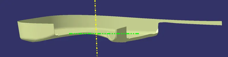
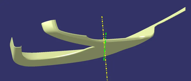
- that makes a closed surface check if that is completely closed or not with the help of boundary command
- if the boundary is shown it will not be completely closed
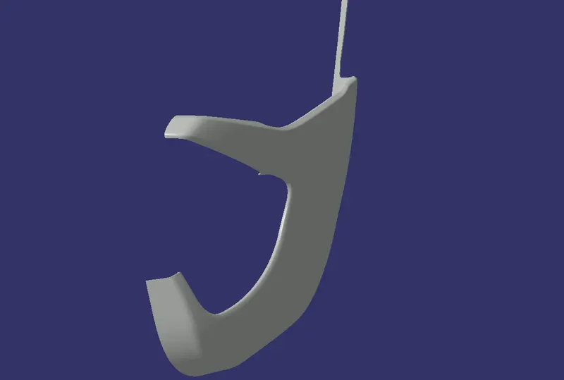
CLOSED BODY
- Close the body with close surface command in a new body named as DOOR PANEL
B SIDE FEATURES
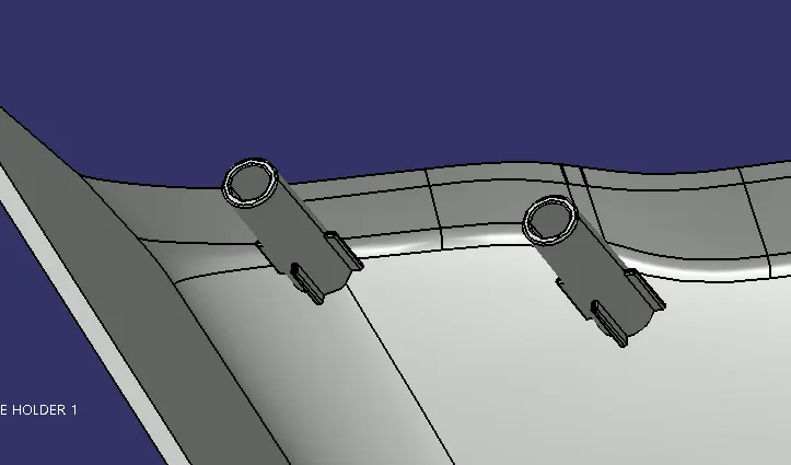
HEAT STAKES
- Extract the lines from the reference master section
- Make a point in the middle of the line projected on the b surface
- Make a plane and draw a sketch with 7.5mm outer diameter and 4.5mm inner diameter and iso constrain the sketch
- Then pad it on a new body named Heat stakes for respective parts for example heat stakes for Arm rest, heat stakes for map pocket
- Draft the pad for 3deg with main tooling axis check it is cutting the body if not do opposite direction
- Fillet every faces with .25mm
- Then on the same plane and point draw equal dimensioned mutually perpendicular lines and constrain them
- Then pad that with thick command and sub category neutral fibre with a thickness of 1.5mm
- Draft each and every sides with neutral face as bottom side with 3 deg
- Fillet every sides
- Union trim ribs with heat stake
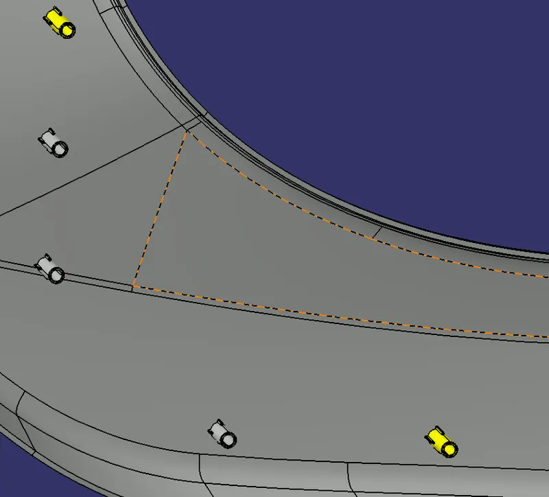
- Copy the whole body and paste special on the whole part for needed numbers
- Make a point where other heat stake is needed connecting other bodies
- Translate the new copied body to that point
- Then trim that with main body
4 WAY LOCATORS
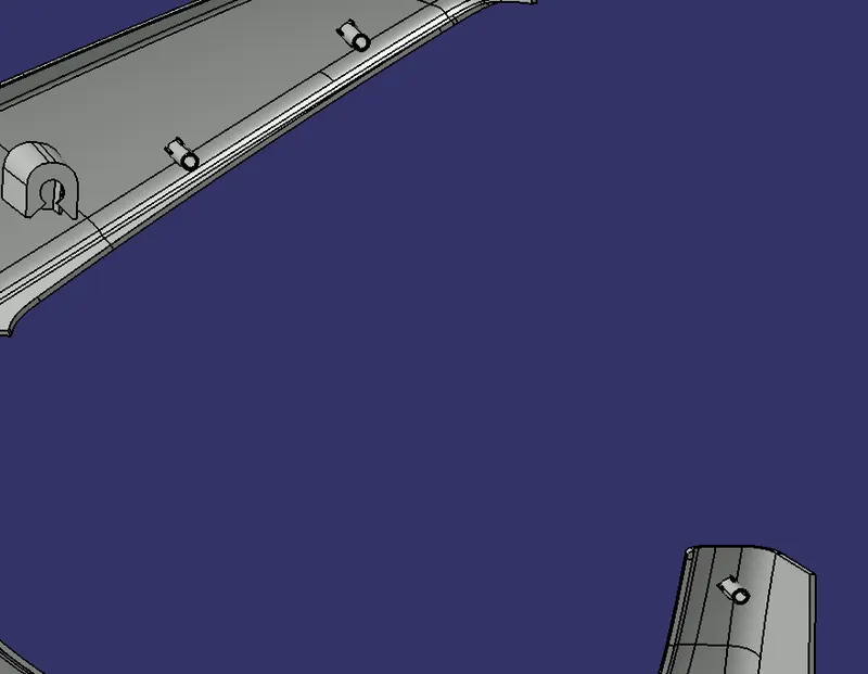
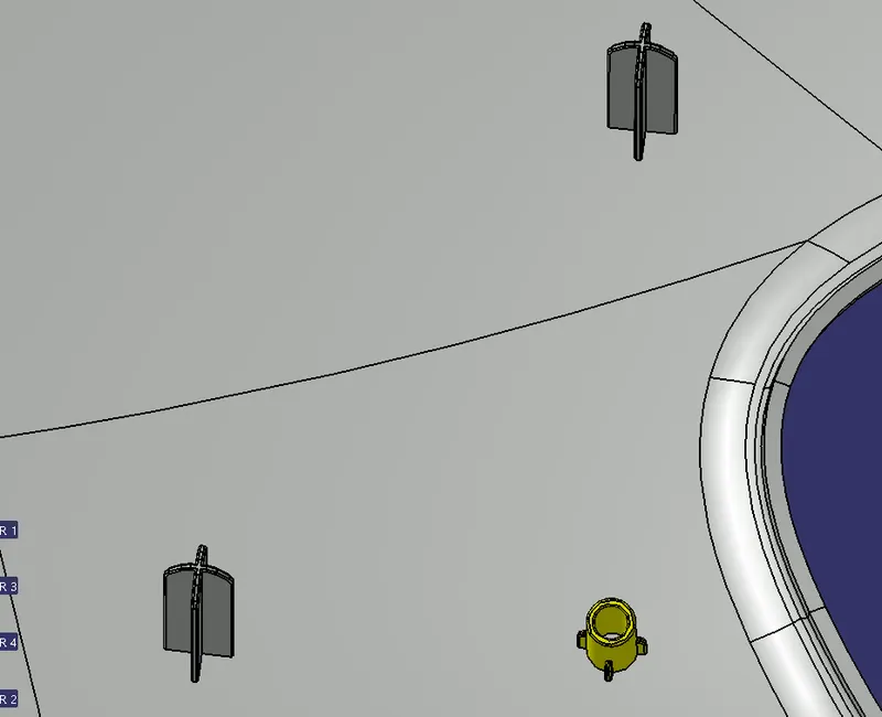
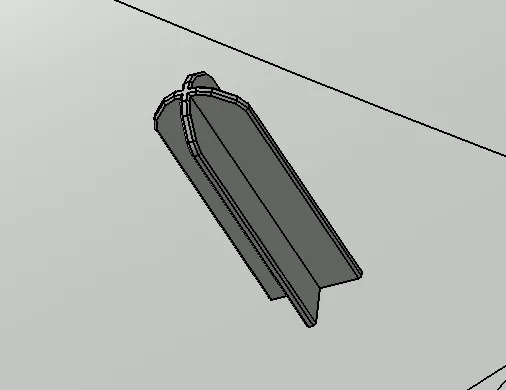
- For 4 ways locator same as that of a Rib for heat stake
- Make a point on the needed surface
- Make a plane wrt to that point and surface
- Select positioned sketch and select the plane and projection point as the point we made
- Make lines of 15mm each perpendicular to each other like ribs
- Pad it on a new body named 4 way locator
- Draft for 3 deg like the ribs
- Chamfer 4 edges for 3 mm and 45°
- Fillet the chamfered edges for 2mm
- Fillet all faces for .25mm
- Make other points for translation then copy, paste special and translate to that points
DOG HOUSE
-
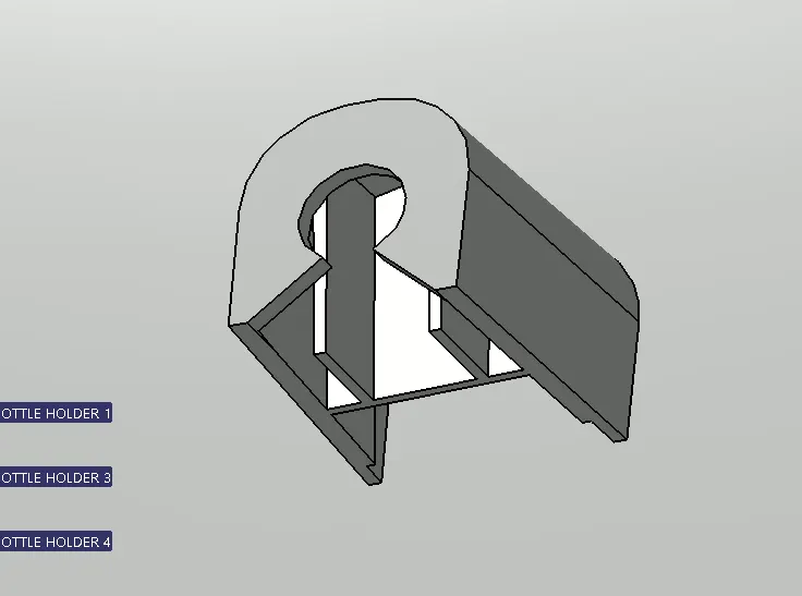
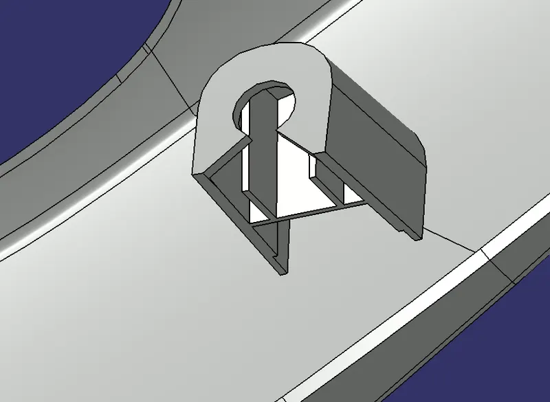
For dog house Make a point on the needed surface
-
Then make an axis system with x and y direction as our needed direction
-
Then with that point make lines perpendicularly to each other
-
Then wrt to the reference draft of the dog house given for project 11
-
Extrude those line
-
And offset them for the length we needed
-
Making a dog house like shape by trimming each surfaces
-
Then fillet the edges
-
Then thicken inside for 2mm inside a new body named Dog house
-
Then draft the outer face for 3 deg wrt main tooling axis
-
Then draft inner face also for 3 deg
-
Then fillet other faces
-
Extract the outer surface
-
Extract the surface the dog house is presented
-
Then offset to satisfy the universal dog house rules and given data
-
Then trim that two surfaces and extrapolate
-
Then split with dog house body
-
Draft that face wrt side core tooling axis
-
Then offset the root surface that is used for the top cover to the given length in the data
-
Then offset the root perpendicular surface wrt to the data
-
Trim those 3 to form a bridge for support of push pin
-
Then thicken the surface for 1.5mm on a new body
-
Draft wrt to the side core tooling axis and trim that body with dog house
-
Make a point on the top surface
-
And add a plane wrt the surface and the point
-
Make a positioned sketch of the top cut needed with the help of the given reference data
-
Then pad it on a new body
-
Remove that body from dog house
-
Draft the cut sides wrt main core tooling axis
-
Fillet all sides for 0.25mm
DRAFT ANALYSIS
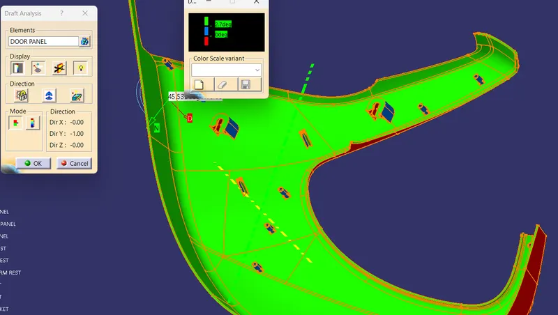
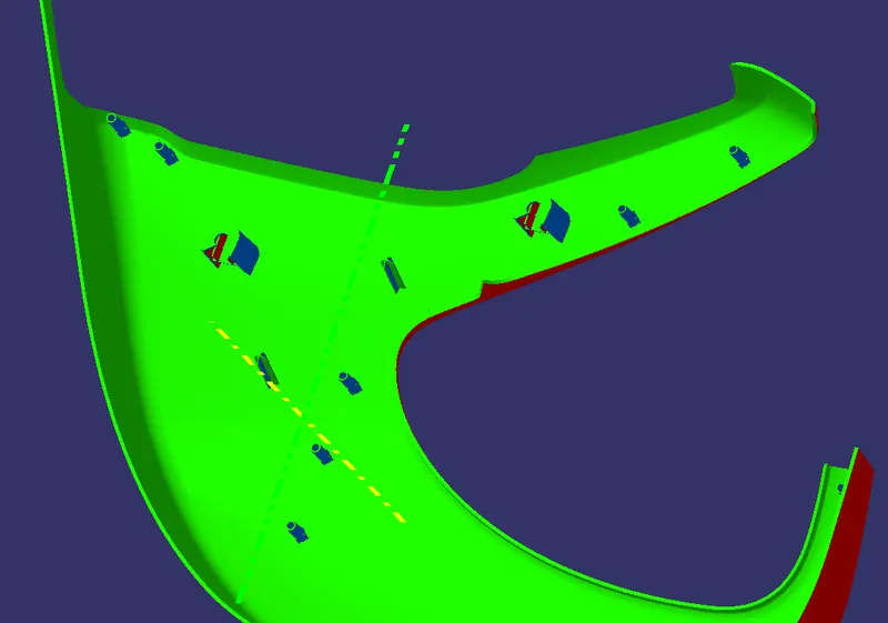
- check whether each and every faces are clearing the draft analysis
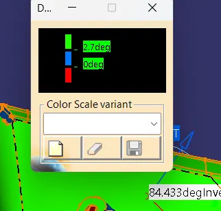
- the nominal value of draft analysis wrt main tooling axis will be 2.7 degree
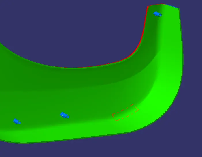
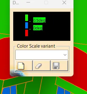
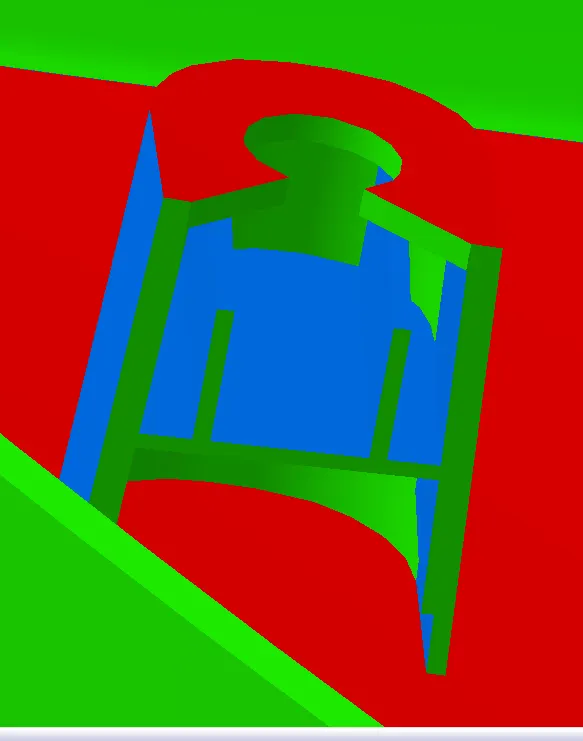
- the nominal value of draft analysis wrt side core tooling axis will be .5 deg
SIDE CORE TOOLING AXIS
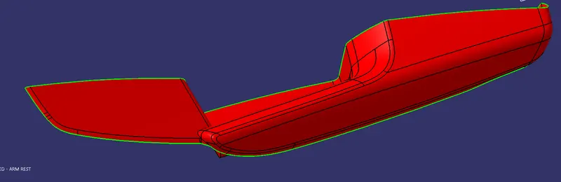
ARM REST
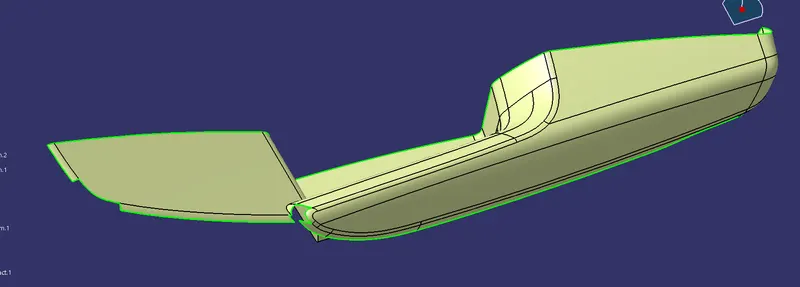
IMPROVED CLASS A SURFACE
- for arm rest by analysing the master section there is a space for the outer material before the class A
- that is for the leather finish
- the distance between leather finish the and the Class A is 2 mm and the thickness of the component will be 2.5 mm
- so offset the given surface to 2mm wrt master section
- from that offset some of the values will be lost
- so as to cover the lost portion we want to extract the surface that is lost from the given surface and offset that to 2mm
- and extrapolate them and trim to get a connected surface
- then for the top fillet extract the boundaries and do a sweep or multi section surface for the fillet
- personally i had done multi section surface
- extrapolate and trim the multi section surface with before trim
- join the final surface with the Class A surface
- That surface will be our Improved class A surface
TOOLING AXIS CREATION
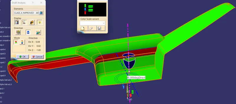
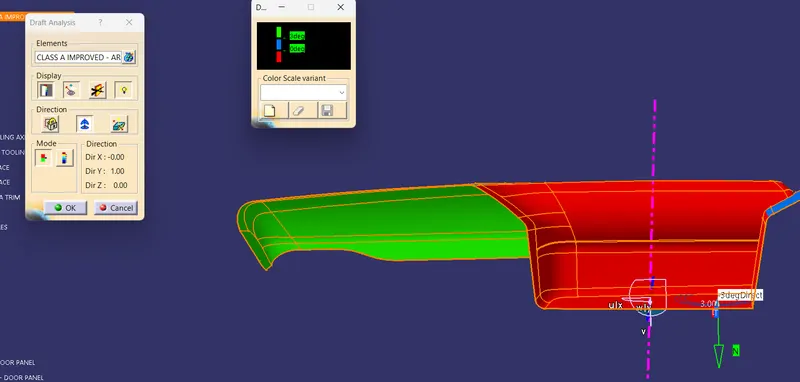
- select a tooling direction and select a surface for a point
- make a line perpendicular to the surface
- if that line passes the draft analysis that will be our MAIN TOOLING AXIS
- then create a line parellel to the surface from the same point
- that will be the SIDE CORE TOOLING AXIS
CLASS B SURFACE
- from the master section given the thickness of the component is 2.5mm
- that will be offseted from the improved class A
- in that offset also there will be some of the surfaces missing
- for compensating that lose we want to do as same as we had done for the improved class A
- and finally join that surfaces together with maximum deviation of 0.01/0.1
- check the boundaries are correct
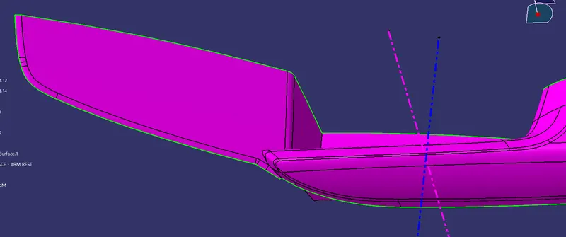
CLASS C SURFACE CREATION
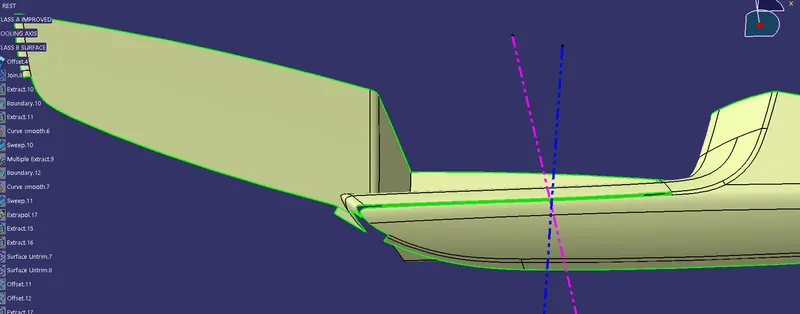
- from the improved class a surface findout the boundaries that can be sweeped with draft direction and others with reference surface
- divide those with the help of perpendicular end and parellel end
- then sweep accordingly
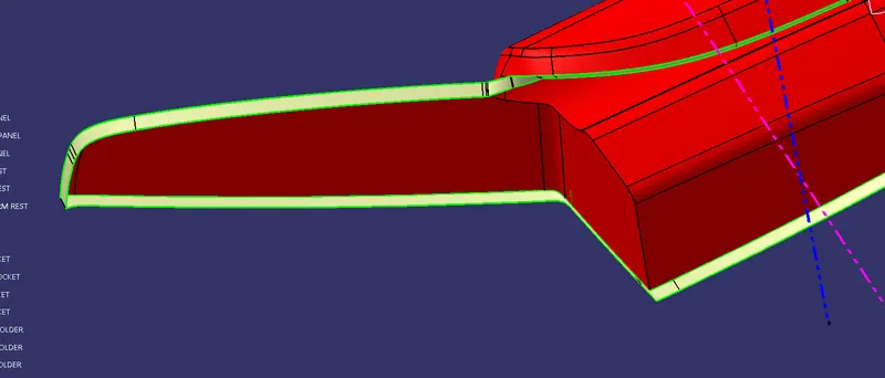
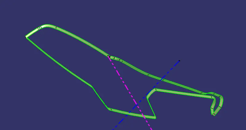
- if there is any complicated curves or retractions create a spline from the end points of nearest sweep and support as outer ends
- then extract the other 3 boundaries
- do multisection surfaces with the sweep side extract as profile and guide curve as spline and boundary
- then join those with max deviation .1mm
- do this procedure for any complicated surfaces
- trim every sweep surfaces with each other
FINAL TRIM
- trim the class a with the class c
- for the final trim inspect for any surfaces from class b that are not passing the class c surface then extrapolate those surface edges and trim that with the above trim ie; class A and C trim with Class B
- that makes a closed surface check if that is completely closed or not with the help of boundary command
- if the boundary is shown it will not be completely closed
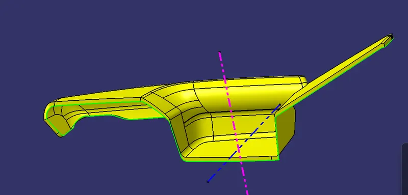
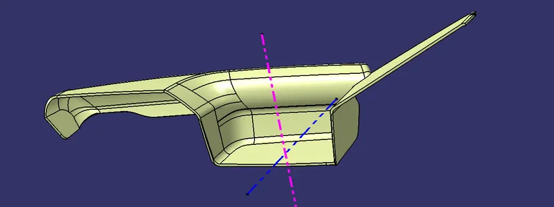
CLOSED BODY
- then add a new body named ARM REST and close the surface
- then check for draft analysis that the closed surface is passing the draft analysis
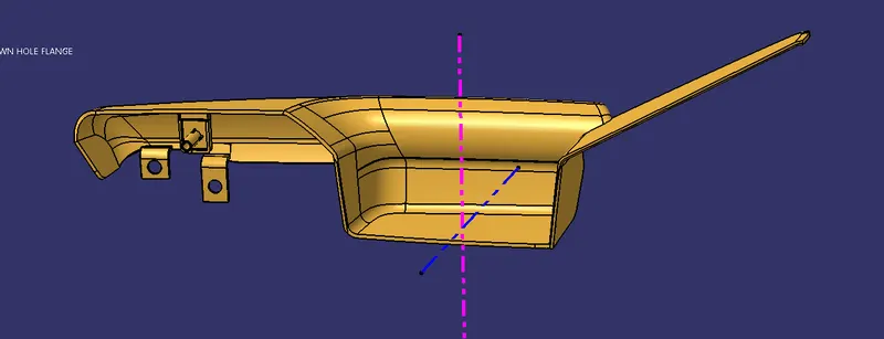
B SIDE FEATURES
- check for the master section for the b side features
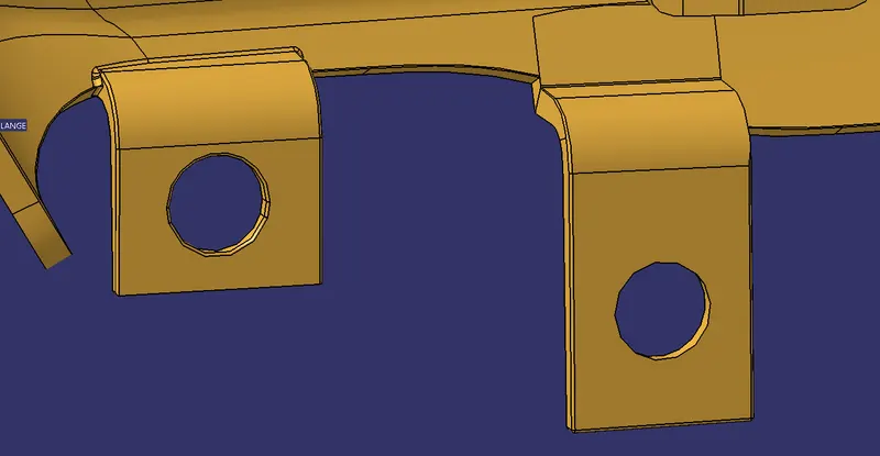
- for flanges with holes for heat stakes extract the required components and and make lines from the end points and extrude those lines and trim those surfaces and thicken those surface on a new body
- then add hole for the flange.
- draft each faces according to the main tooling axis and side core tooling axis
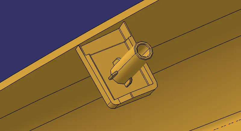
- for the heat stake flange/SEMI DOG HOUSE
- for a better sturtdiness i had used a semi dog house
- extracted every lines and make new lines and trim those with the surfaces
- then thicken the surface in a new body and extract the outer surfaces in a single extract and offset the base surface for about 3-6mm then offset the outer surface to 1.2mm
- then trim those 2 surfaces and split the body with this surface
- then add heat stake with the help of the master section the outer diameter is 7.5mm and inner is 4.5mm then added those to circles inside a sketch and paded it on a new body
- then add ribs of length 5 mm on the both sides on a new sketch and pad it on a new body to 10mm and reverse direction same as heat stake
- add drafts for each bodies
- union trim ribs with heat stake and then that with dog house and then that with arm rest
- same for the other two flanges
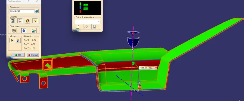
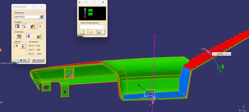
DRAFT ANALYSIS
- Do draft analysis WRT main tooling axis as well as side core tooling axis and check whether it passes the draft analysis
MAIN TOOLING AXIS
SIDE CORE TOOLING AXIS
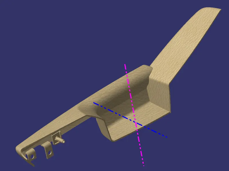
APPLY MATERIAL
- apply material for the whole body using a colour tone
MAP POCKET
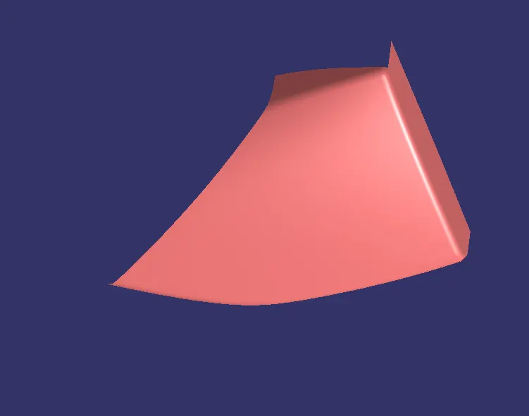
CLASS A SURFACE
TOOLING AXIS
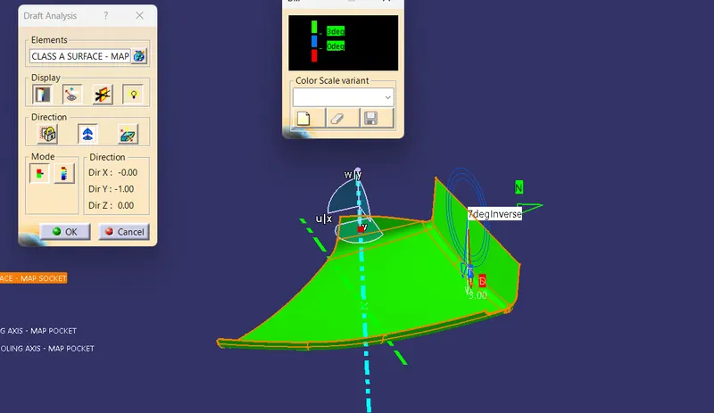
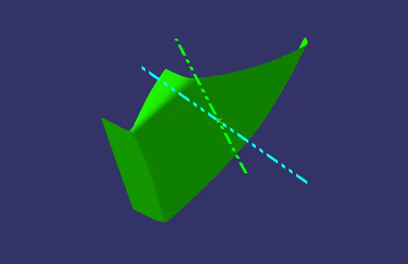
- select a tooling direction and select a surface for a point
- make a line perpendicular to the surface
- if that line passes the draft analysis that will be our MAIN TOOLING AXIS
- then create a line parellel to the surface from the same point
- that will be the SIDE CORE TOOLING AXIS
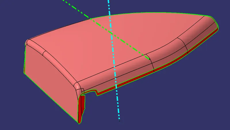
CLASS B SURFACE
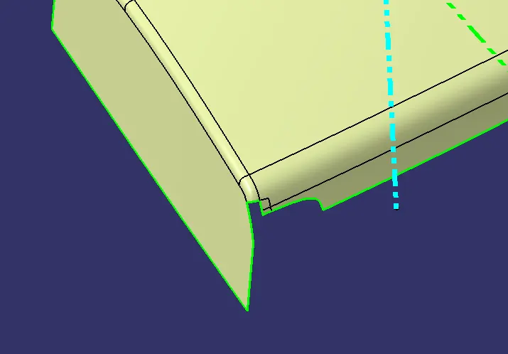
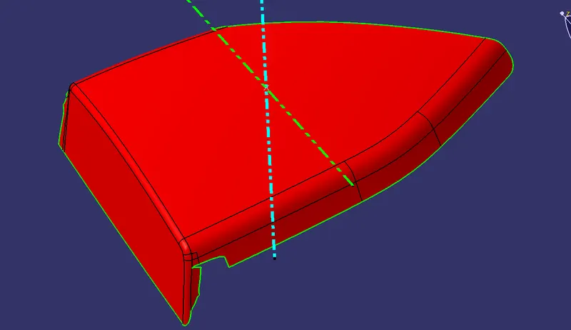
- offset the class a to 2.5mm as given in the master section
- when offseting some of the face was missing
- so as to clarify that missing places
- select join command and clear the whole missing connections
- and make them 2 surfaces
- multiple extract each of the surface and extrapolate them to intersect each other
- trim those surfaces and find out the fillet value and add that to the class b surface
CLASS C SURFACE
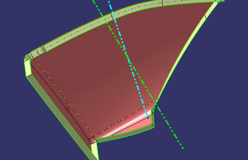
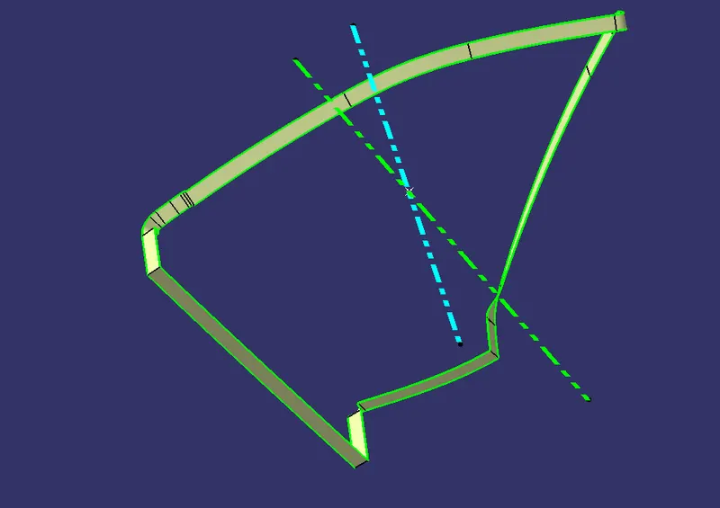
- from the improved class a surface findout the boundaries that can be sweeped with draft direction and others with reference surface
- divide those with the help of perpendicular end and parellel end
- then sweep accordingly
- if there is any complicated curves or retractions create a spline from the end points of nearest sweep and support as outer ends
- then extract the other 3 boundaries
- do multisection surfaces with the sweep side extract as profile and guide curve as spline and boundary
- then join those with max deviation .1mm
- do this procedure for any complicated surfaces
- trim every sweep surfaces with each other
FINAL TRIM
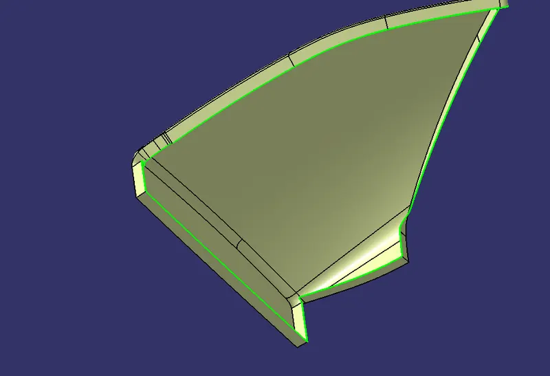
- trim the class a with the class c
- for the final trim inspect for any surfaces from class b that are not passing the class c surface then extrapolate those surface edges and trim that with the above trim ie; class A and C trim with Class B
- that makes a closed surface check if that is completely closed or not with the help of boundary command
- if the boundary is shown it will not be completely closed
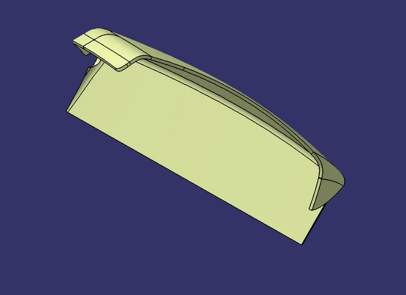
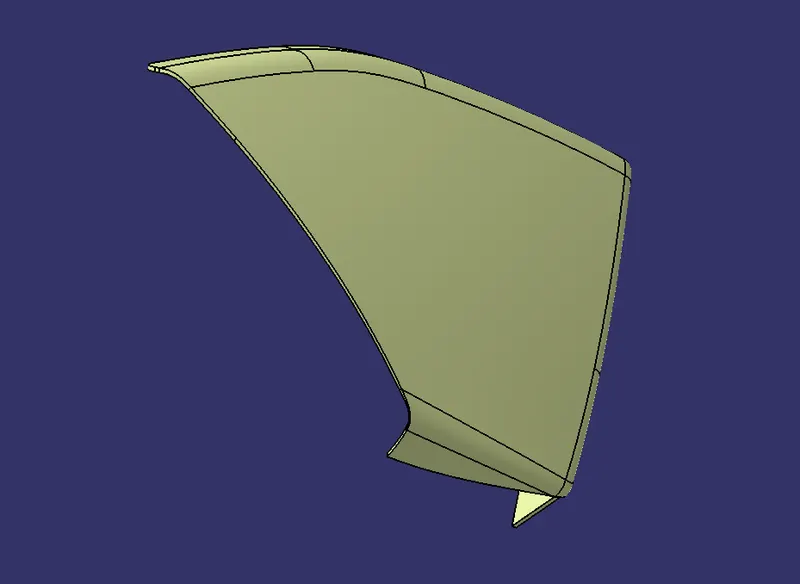
CLOSED BODY
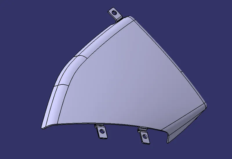
- close the surface in a new part body named MAP POCKET
B SIDE FEATURES
HEAT STAKE FLANGES
- check for the master section for the b side features
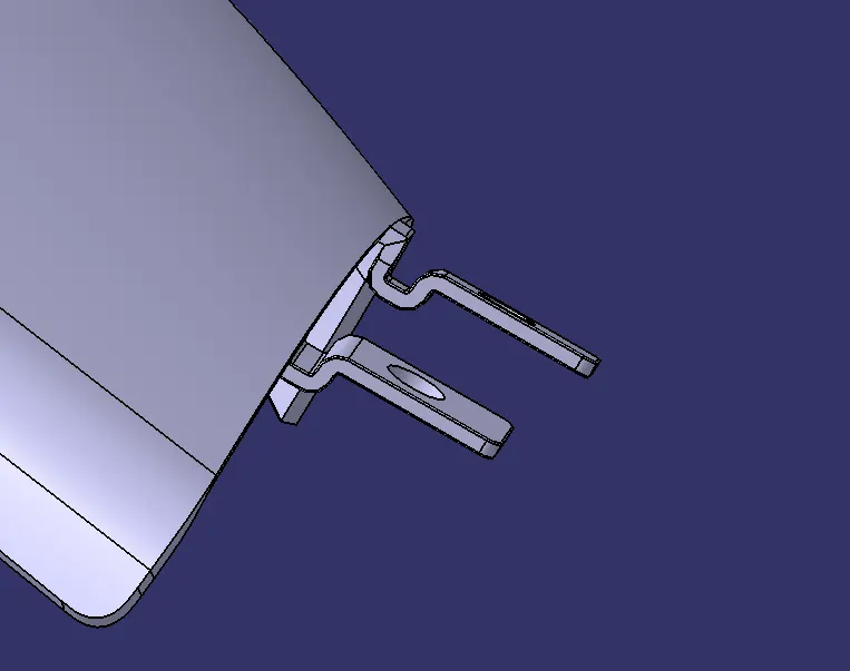
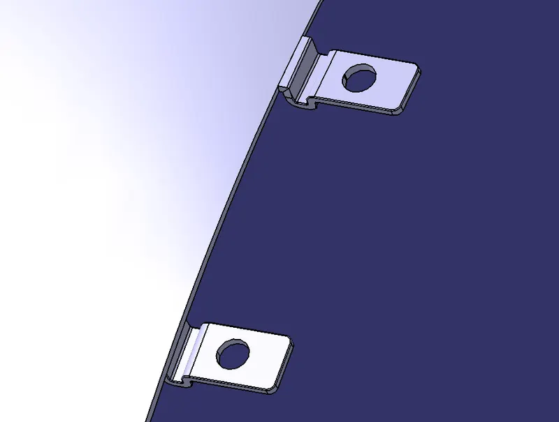
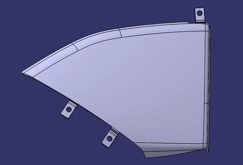
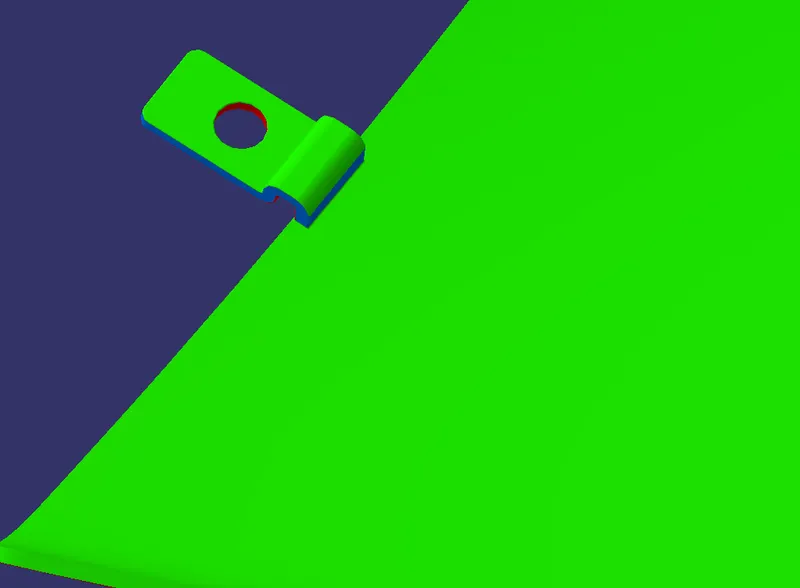
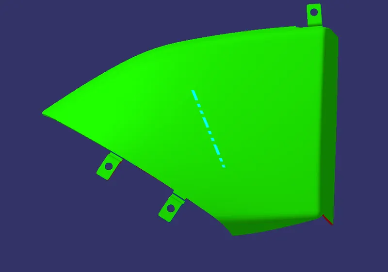
- for flanges with holes for heat stakes extract the required components and and make lines from the end points and extrude those lines and trim those surfaces and thicken those surface on a new body
- then add hole for the flange.
- draft each faces according to the main tooling axis and side core tooling axis
- copy and paste special to translate each flanges to given multi section places and with corresponding to then heat stakes on the DOOR PANEL
DRAFT ANALYSIS
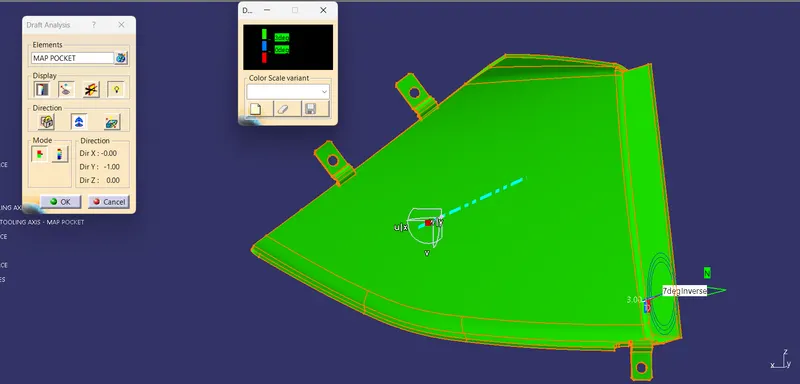
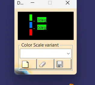
- check whether each faces clear the draft analysis
- the nominal value of draft analysis is 2.7 degree
BOTTLE HOLDER
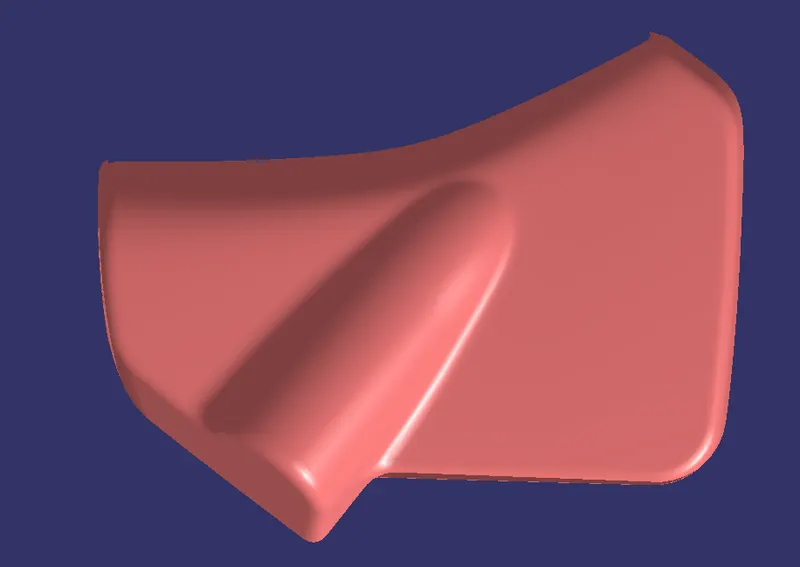
CLASS A SURFACE
TOOLING AXIS
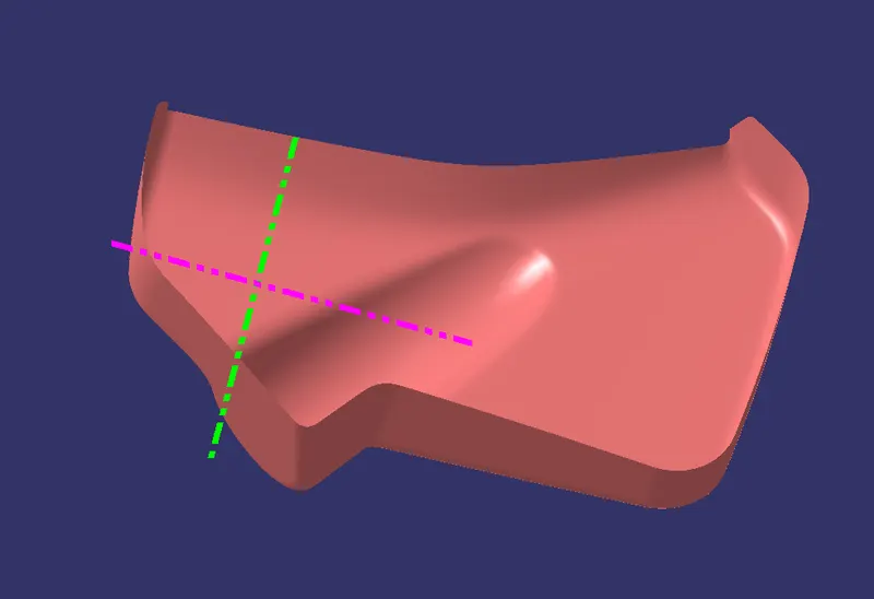
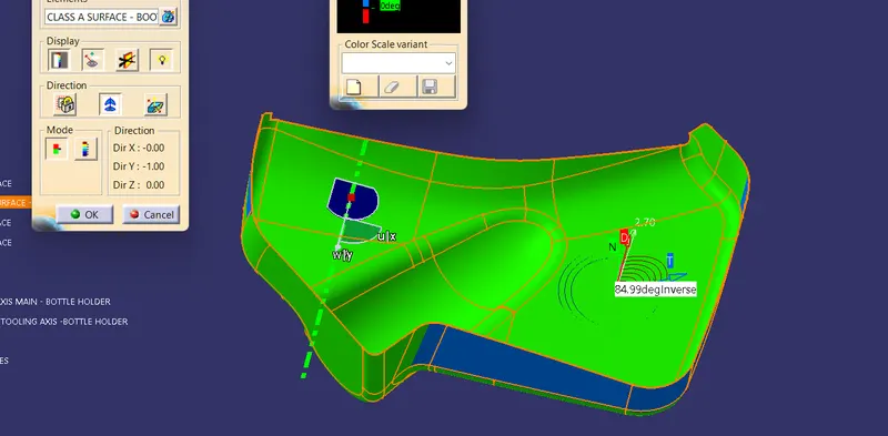
- select a tooling direction and select a surface for a point
- make a line perpendicular to the surface
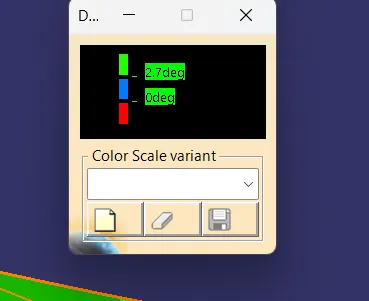
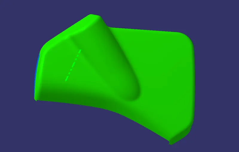
- if that line passes the draft analysis that will be our MAIN TOOLING AXIS
- then create a line parellel to the surface from the same point
- that will be the SIDE CORE TOOLING AXIS

CLASS B SURFACE
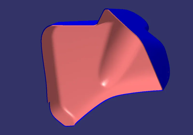
- check for the thickness in master section given
- the given thickness is 2.5mm
- then offset the class A surface to required position
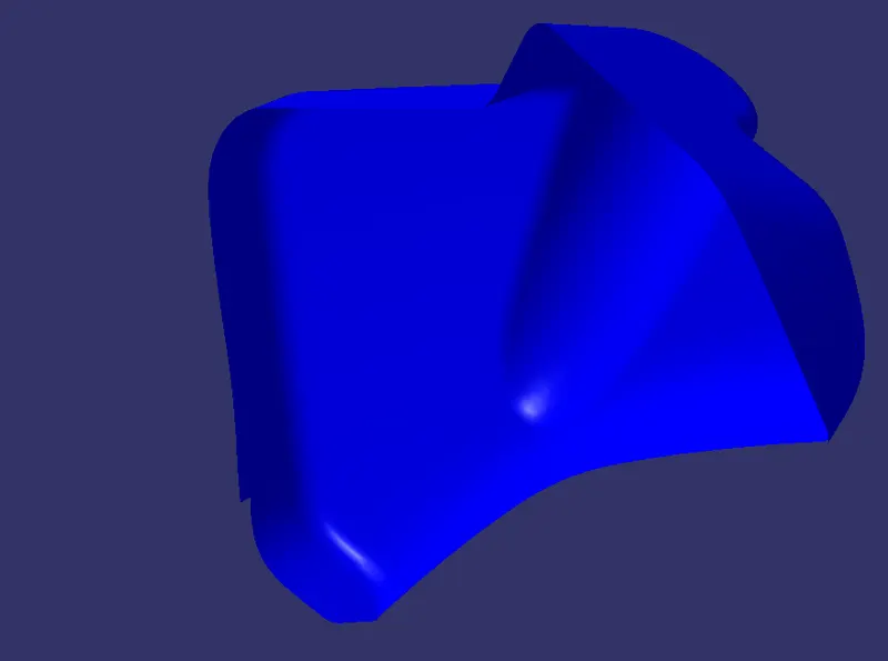
CLASS C SURFACE
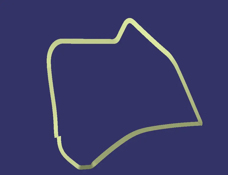
- from the improved class a surface findout the boundaries that can be sweeped with draft direction and others with reference surface
- divide those with the help of perpendicular end and parellel end
- then sweep accordingly
- if there is any complicated curves or retractions create a spline from the end points of nearest sweep and support as outer ends
- then extract the other 3 boundaries
- do multisection surfaces with the sweep side extract as profile and guide curve as spline and boundary
- then join those with max deviation .1mm
- do this procedure for any complicated surfaces
- trim every sweep surfaces with each other
FINAL TRIM
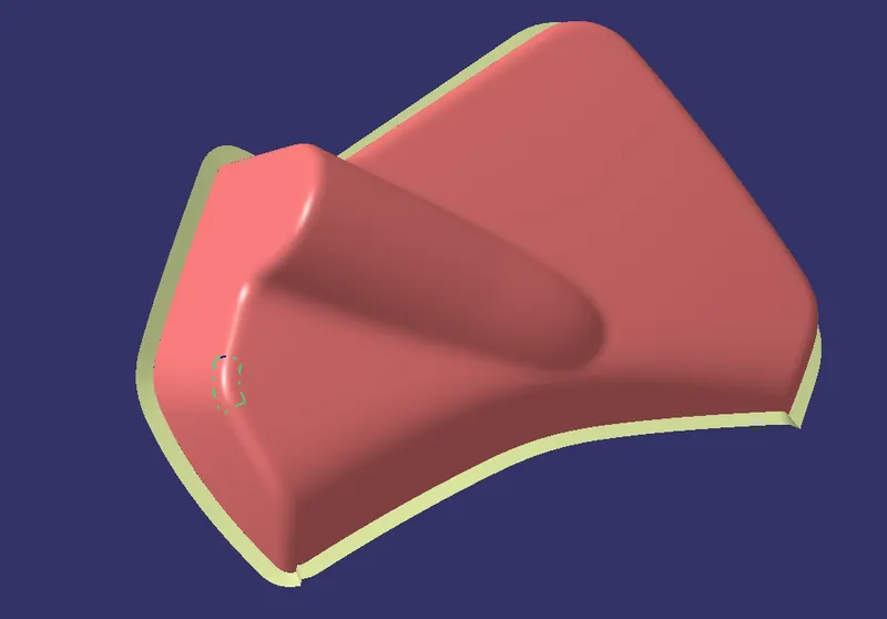
- trim the class a with the class c
- for the final trim inspect for any surfaces from class b that are not passing the class c surface then extrapolate those surface edges and trim that with the above trim ie; class A and C trim with Class B
- that makes a closed surface check if that is completely closed or not with the help of boundary command
- if the boundary is shown it will not be completely closed
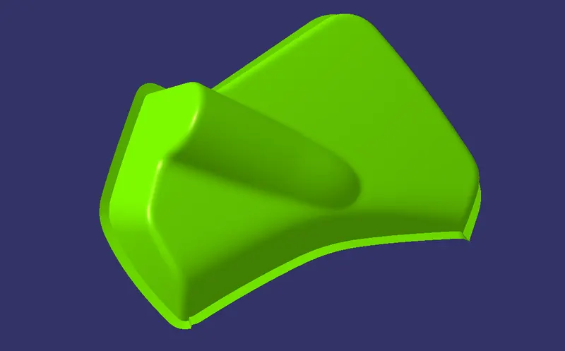
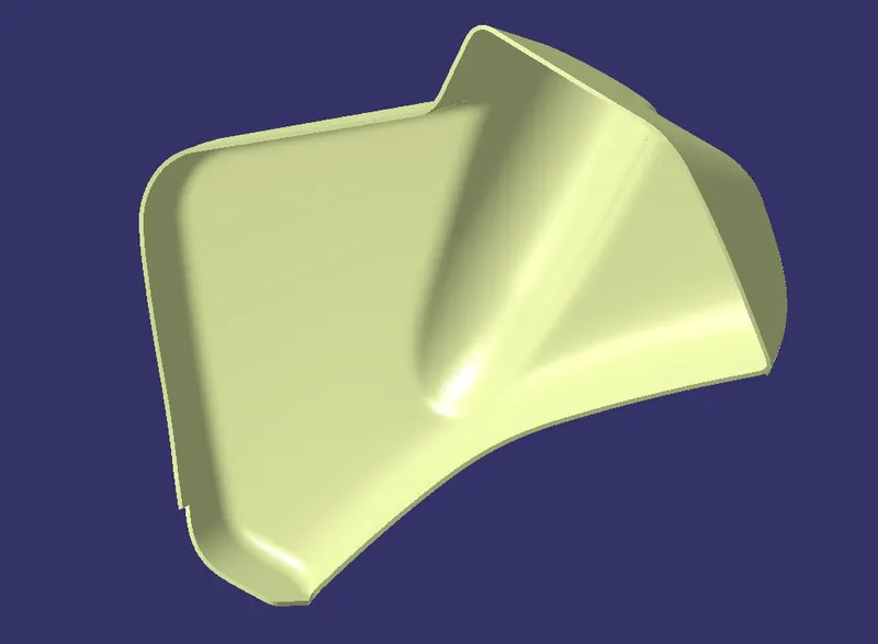
CLOSED BODY
- close the final trim on a new body named BOTTLE HOLDER
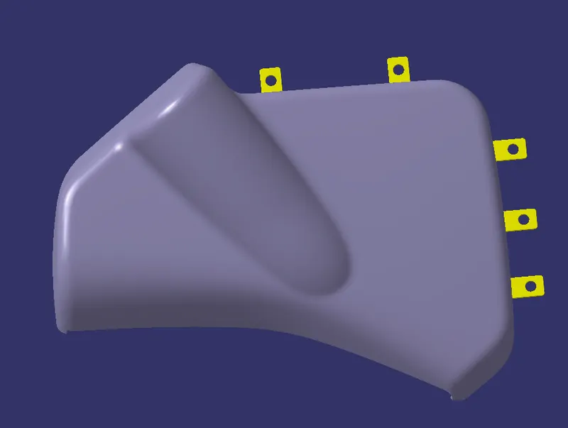
B SIDE FEATURES
- for the b side features initially select a surface and create a point on the surface for creating flanges for the heat stake penetration with respect to the heat stakes on the door panel
- then make a line wrt to the point and facing the heat stake on the door panel then thicken the surface on a new body
- split it with the surface for the length needed
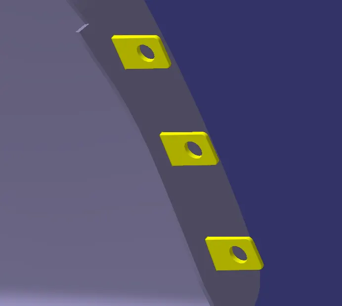
- then for the holes for the heat stake to penetrate in make hole of 8.5mm diameter on the exact middle of the heat stake on the door panel
- then draft each faces according main tooling axis and side core tooling axis as the values 3 degrees and .5 degrees for side core tooling axis
- add fillets at the very edge as 2 mm
- and for other the fillet value will be .25mm
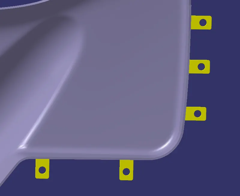
- then make points wrt to the heat stakes on the door panel and copy the body and paste special to the number of flanges that are needed
- then union trim each with the bottle holder
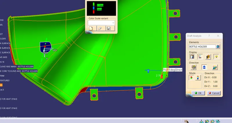
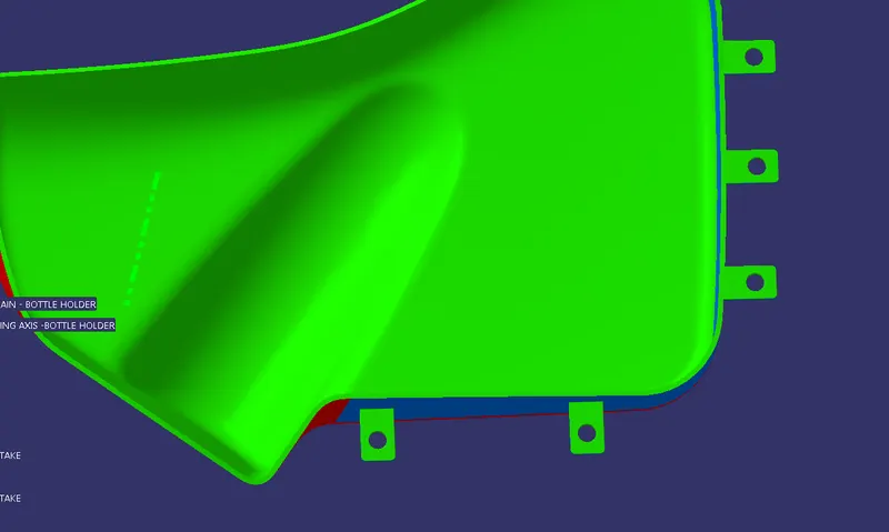
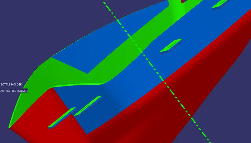
DRAFT ANALYSIS
- do the draft analysis for checking that the made body clears the draft requirements
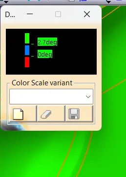
- the nominal draft values of main core tooling axis is 2.7 deg
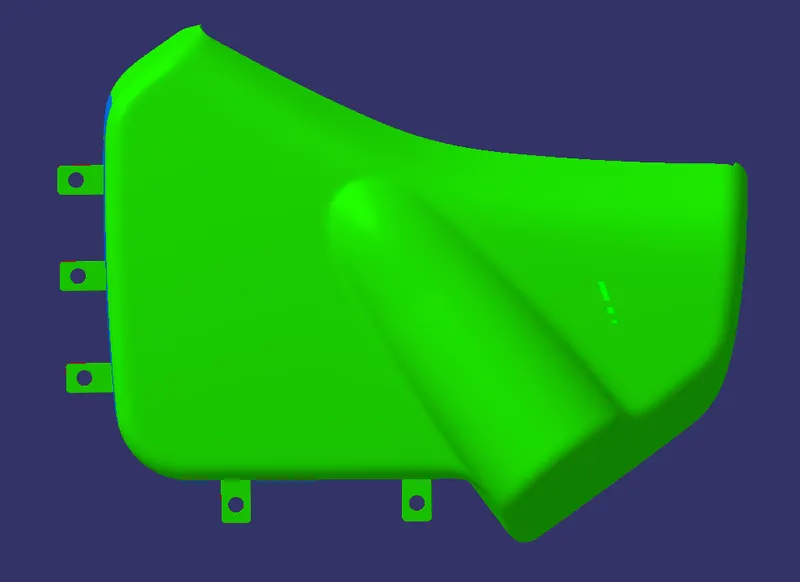
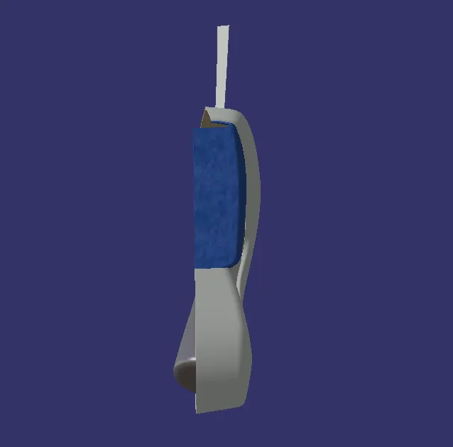
WHOLE COMPONENT ON DIFFERENT ORIENTATIONS
FRONT VIEW
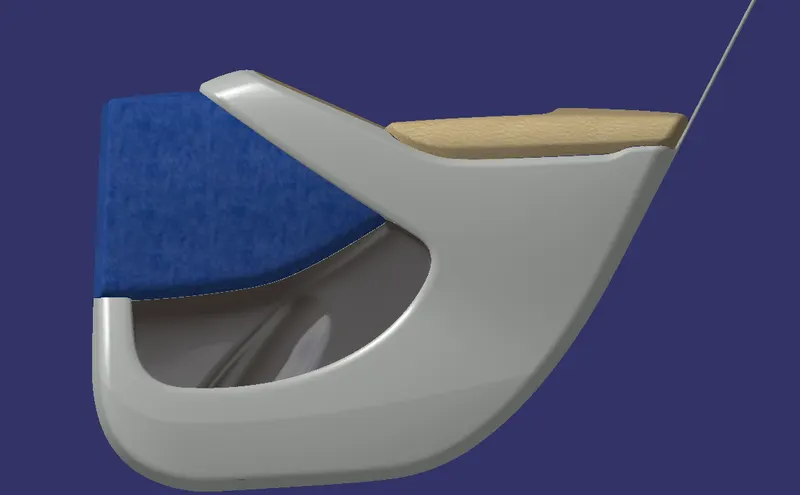
ISOMETRIC VIEW
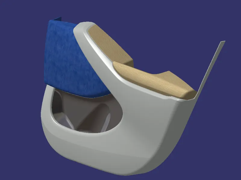
TOP VIEW
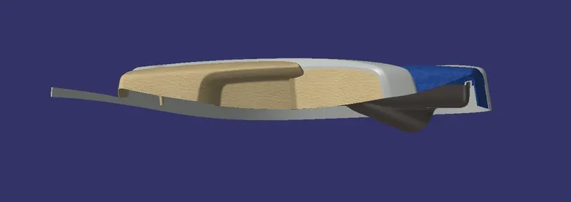
BACK VIEW
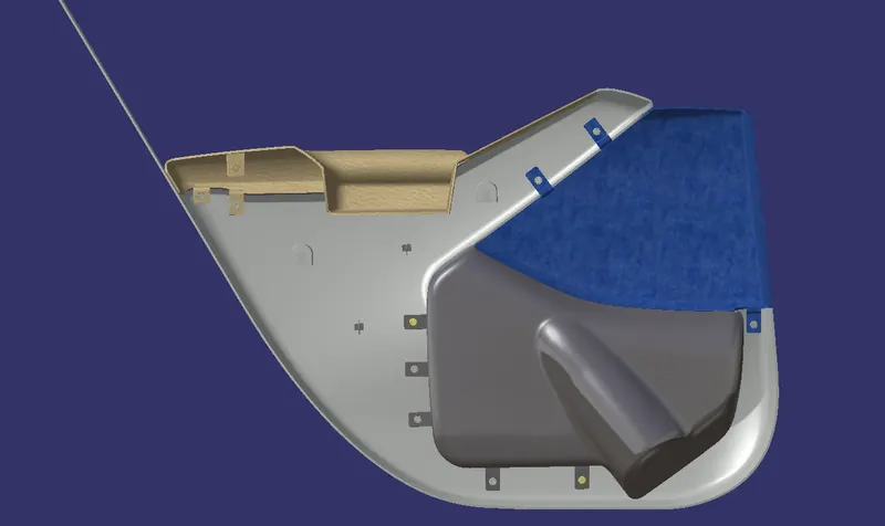
SIDE VIEW
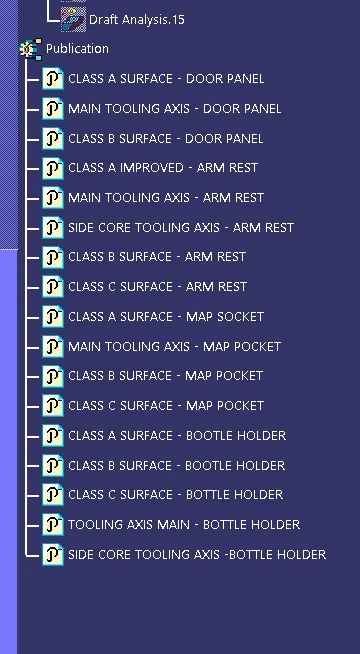
PUBLICATIONS
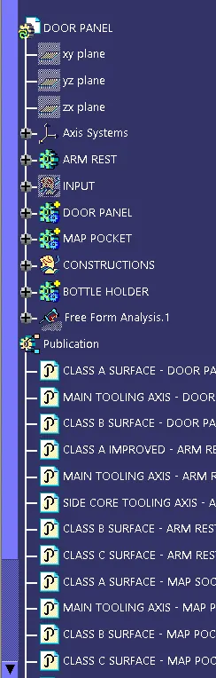
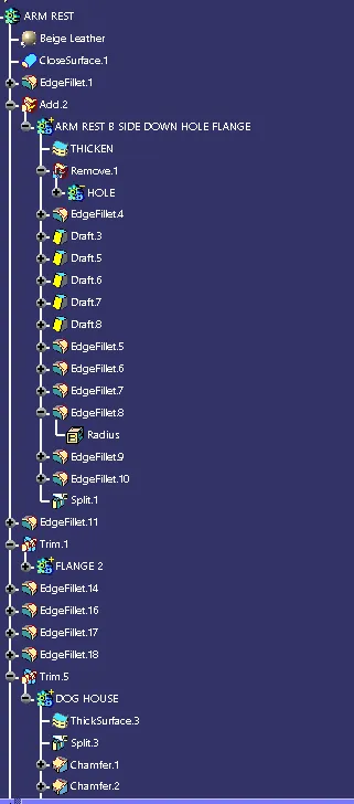
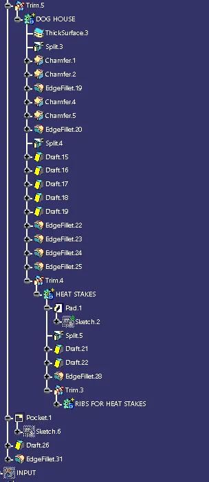
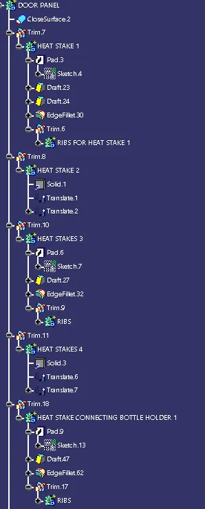
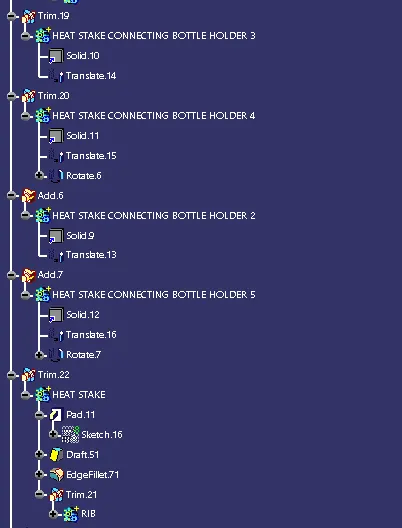
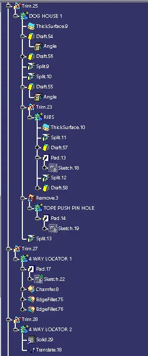
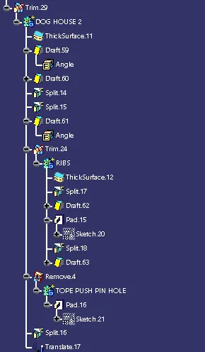
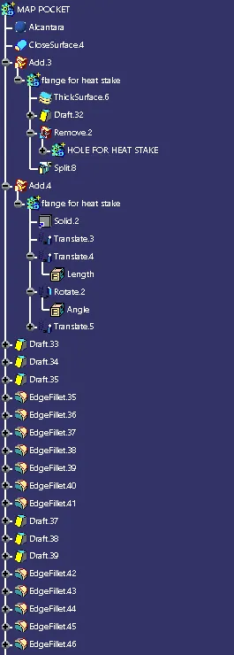
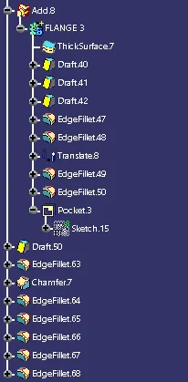
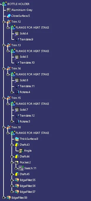
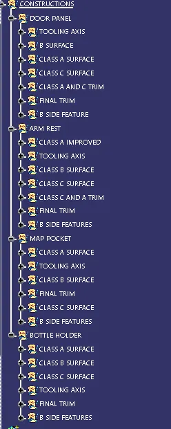
TREE STRUCTURE
ASSEMBLY
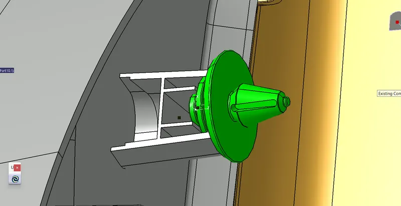
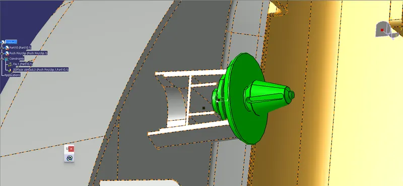
- for assembling the part and the push pin open assembly workbench
- add 2 parts
- then move apart those
- fix the door panel on to the middle portion
- then constrain the push pin with coincide and surface contact on to the dog house surface we created
- then update the assembly