Week 10 - Challenge 1- Attachment Feature Creation (Ribs & Screw Boss)
DOOR HANDLE
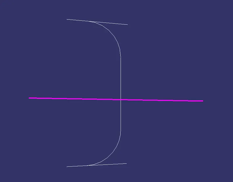
TOOLING AXIS CREATION
- find a tooling direction
- select a point on a surface
- make a axis on the point
- make a intersect on the middle plane
- then throught the draft lines make a line between there connecting points
- make a bisecting line from the draft line with the point
- that will be our tooling axis
CLASS A DRAFT ANALYSIS
- do draft analysis wrt the tooling axis so made
- check the draft report
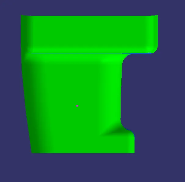
PUBLICATIONS
- Publish class a and tooling axis
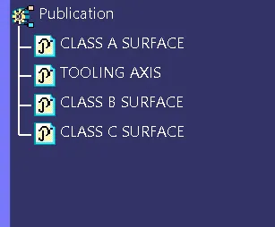
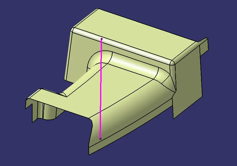
CLASS B SURFACE
- extract and untrim every unfilleted face
- extrapolate them to pass each faces
- then trim them accordingly
- offset the final trim
- extract diff fillets and untrim them and measure there fillet values
- add fillets accordingly
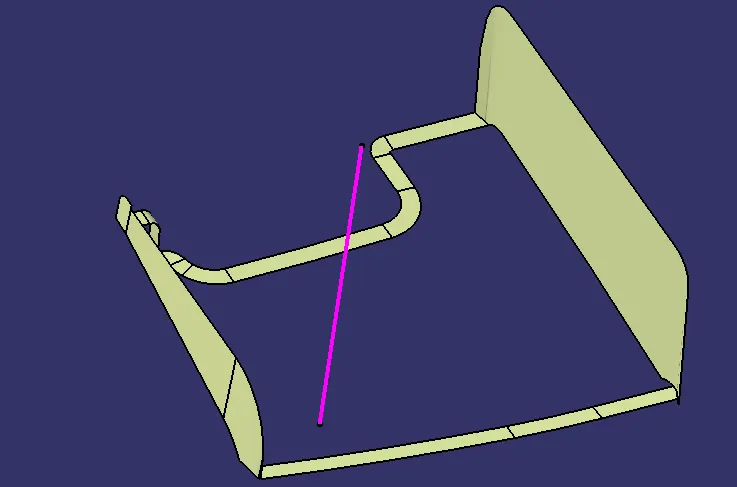
CREATE CLASS C SURFACE
- check wheather the class A end positions are perpendicular or parellel
- select each boundaries accordingly
- if the edge is perpendicular to the tooling axis then do sweep with draft direction and with outside draft of 3 deg WRT tooling axis
- if the edge is parellel do sweep with respect to reference surface and with a inward angle of 90 deg
- extrapolated each of them for trim
- then trim those to join as a one surface
JOINING CLASS A WITH C SURFACE
- extrapolated each surface edges to trim
- final trim without any gap
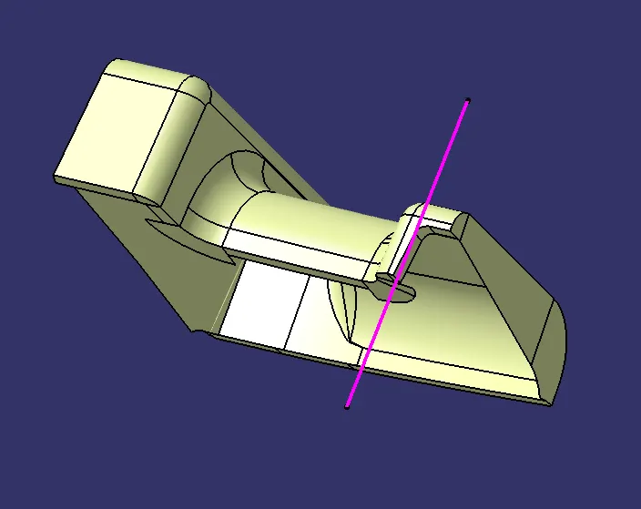
JOIN THE 3 SURFACES TOGETHER
- trim the surface with B surface to get a closed surface
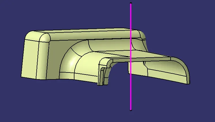
- then close surface in the part body
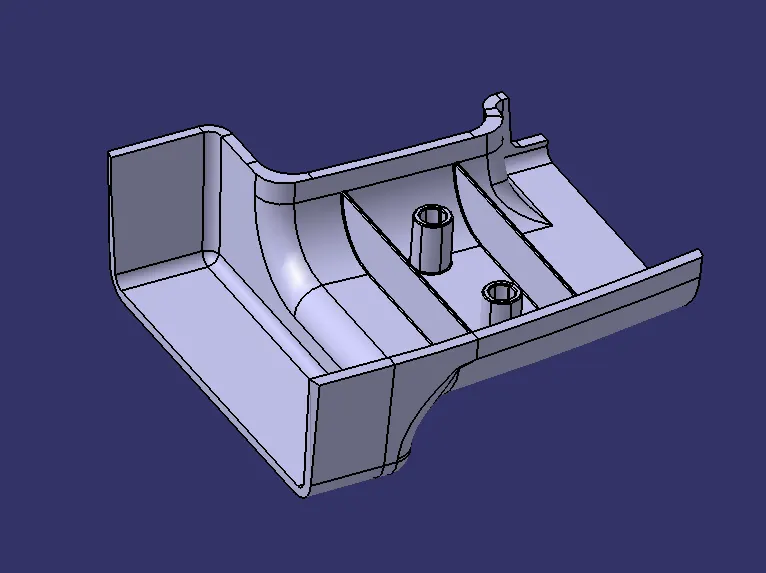
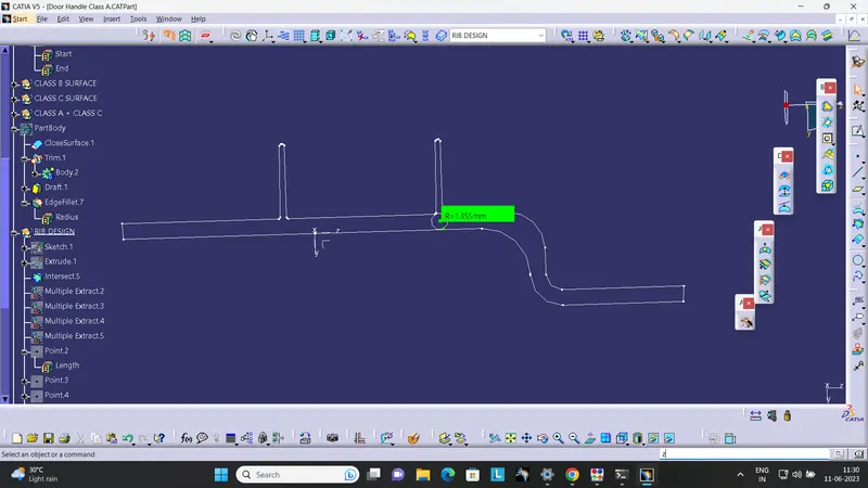
RIB DESIGN
- add a new sketch wrt the axis system made earlier
- in that draw to straight lines wrt the design rules
- extract the line wrt rib rules
- thicken the surface in both sides on a new body
- union trim that with respect to the main body
- do draft with 0.5 deg on each side
- add fillets of 0.25 mm
- check the root diameter
- the top length
- check each and every parameters according to design rule
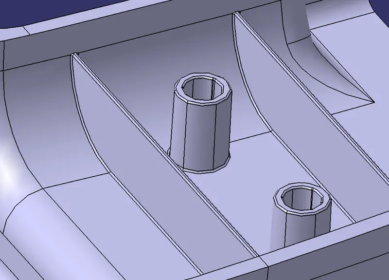
SCREW BOSS DESIGN
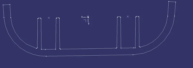
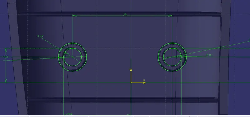
- then draw two sets of circles of diameter 5.2 and 8.2 (calculated from the design equation of screw boss)
- then pad it on a new body
- trim with main part body
- do draft on inside and outside of the screw boss
- add fillets and check the values according to the given calculations
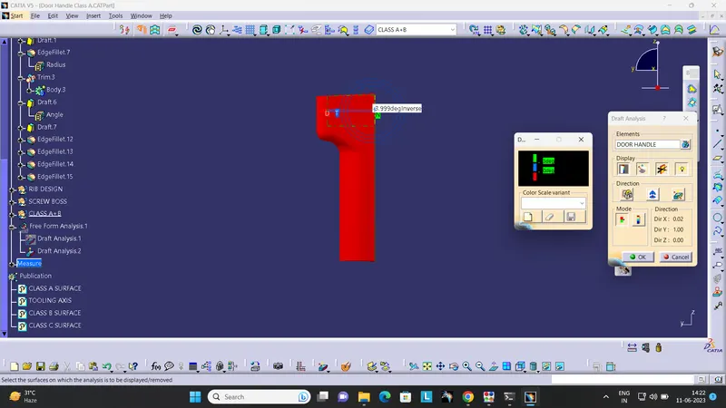
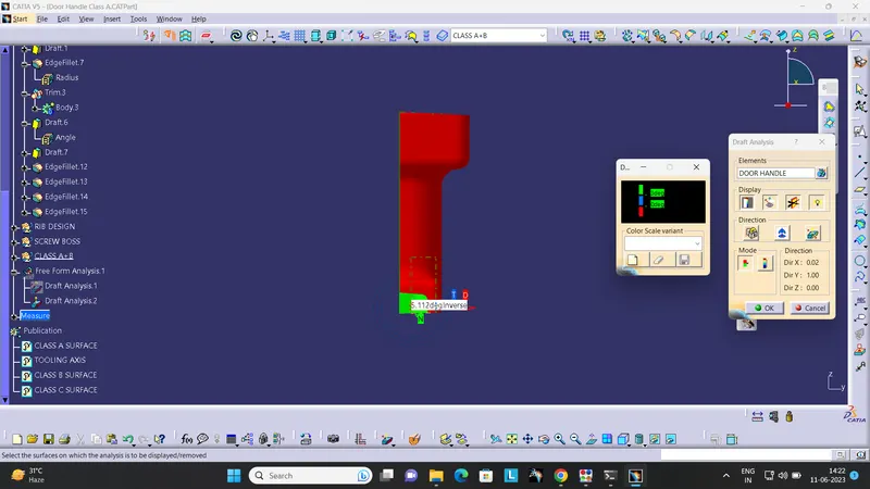
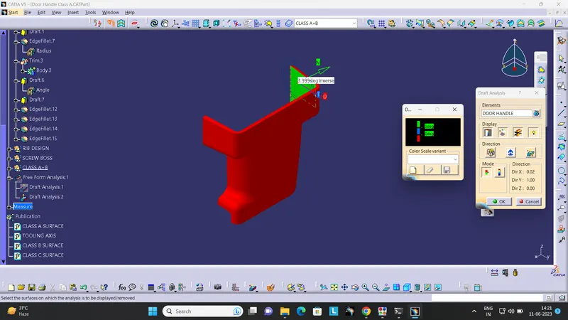
FINAL DRAFT ANALYSIS
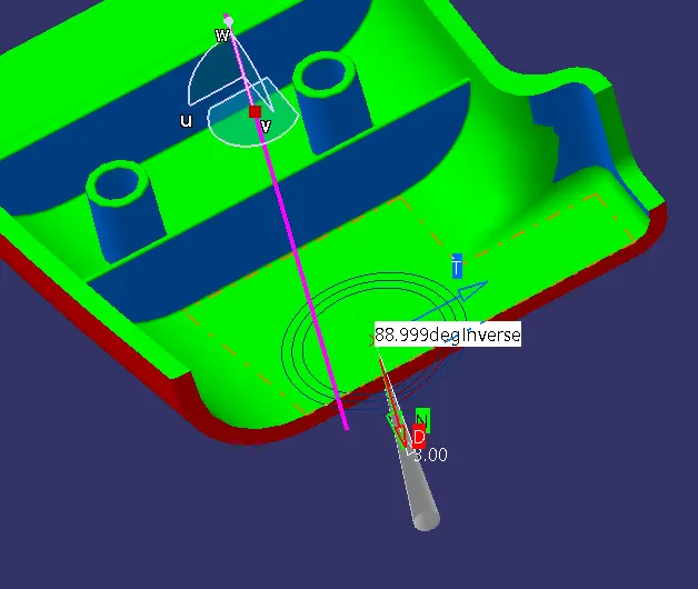
- done draft analysis with respect to tooling axis and values are attached
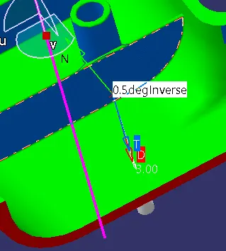
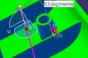
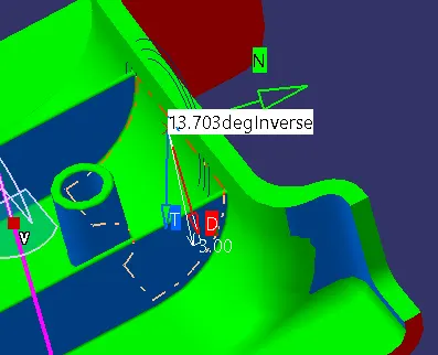
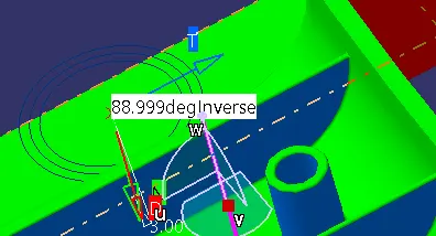
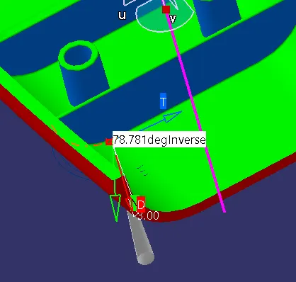
3D VIEWS OF DRAFT ANALYSIS
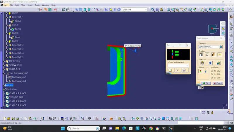
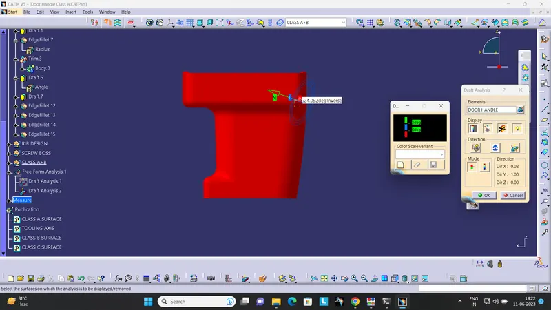
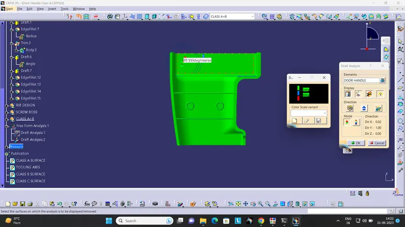 \
\