Week 12- Final project
Ans 1
Aim
To design the lower door trim from the given input, along with the engineering features to assemble the product whenever needed.
Requirements to achieve our objectives.
- Create thickened part using the master section for reference
- Create the mounting features as per design guidelines in the industry and with master sections
Door trim
It is an assembly of many components that join together, and it serves the purpose of aesthetics and provides a seat for some of the controls.
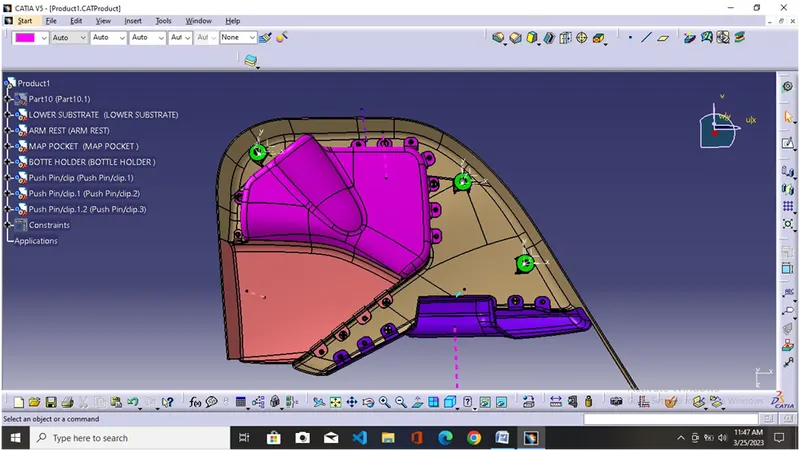
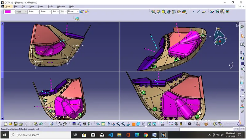
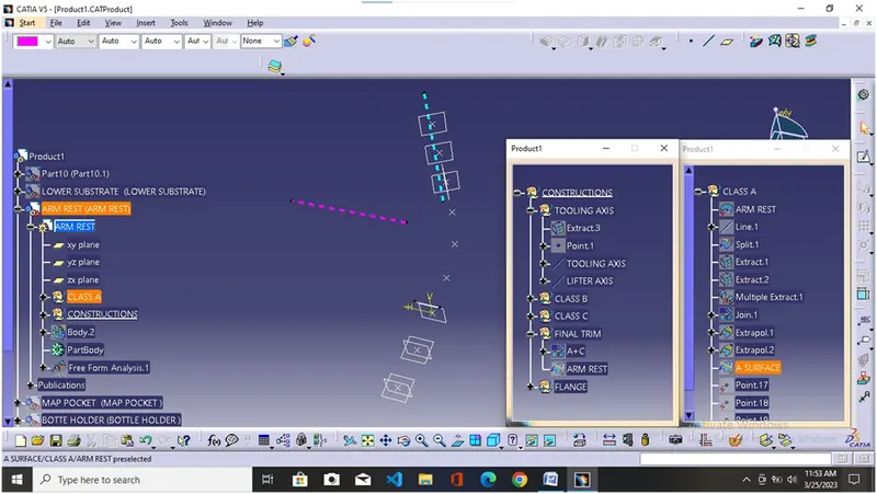
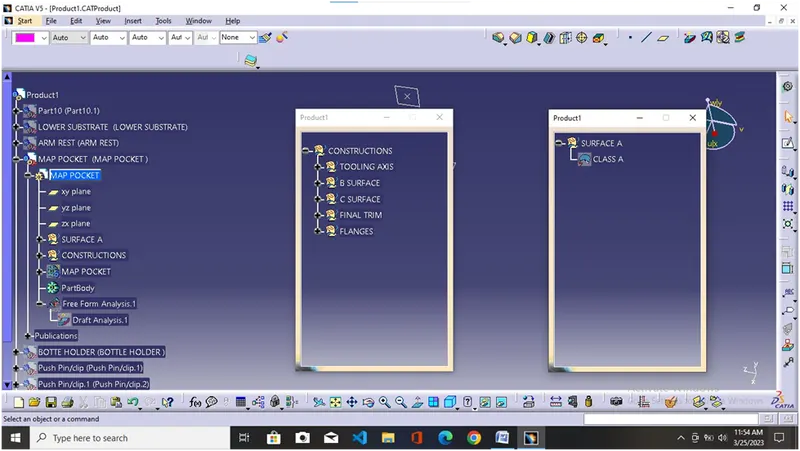
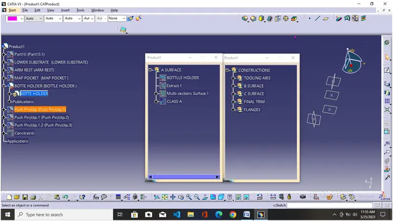
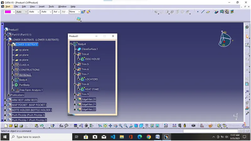
Here are assembly contains the following parts.
- Lower Substrate
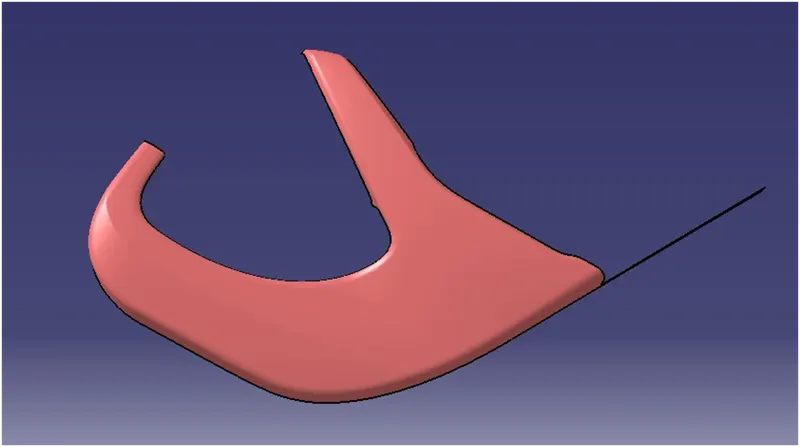
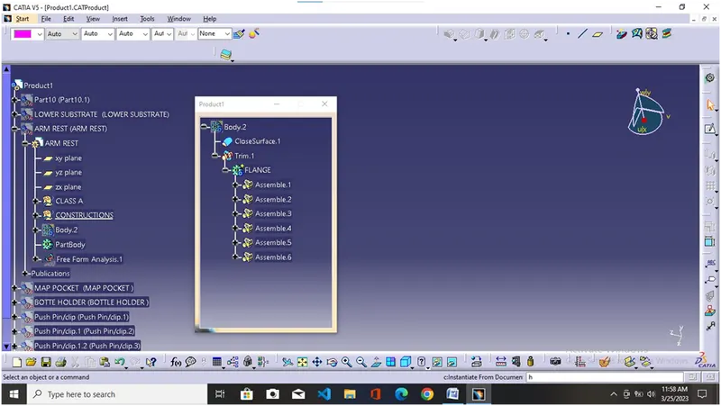
- Arm Rest
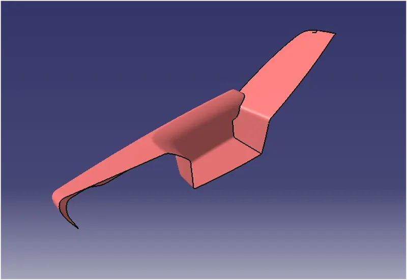
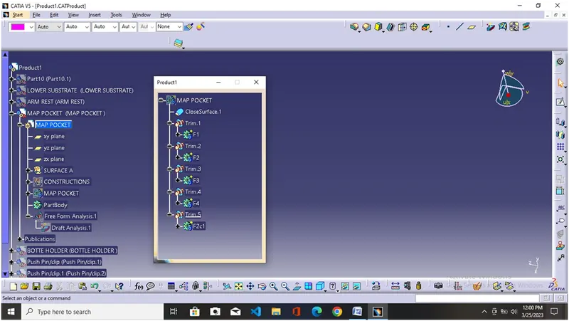
- Map Pocket
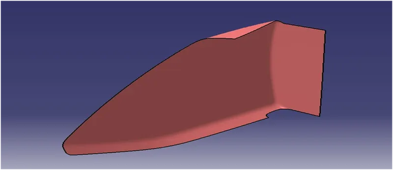
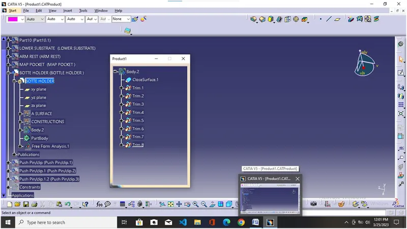
- Bottle Holder
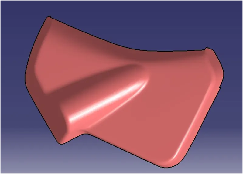
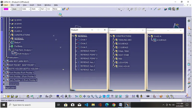
Tooling Axis
It is the direction along which the mold opens for easy ejection of the solid part.
Number of processes to select Tooling Axis
- By making tooling axis along the X, Y, and Z axis
- By making the tooling axis normal to the part surface
- By using the bisection method
We can use any method but for the easy and fast process we go in order as mentioned above and once we find the tooling axis we need not go any further.
Draft
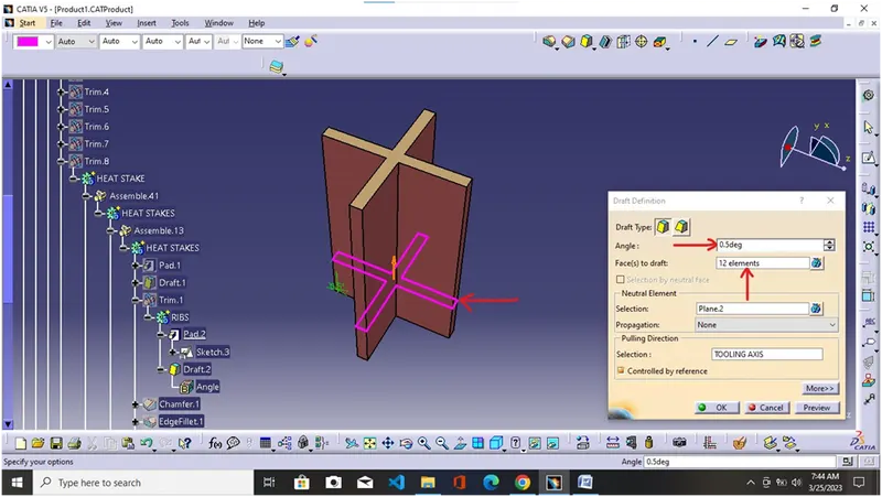
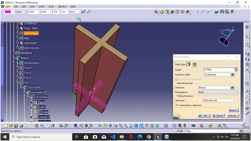
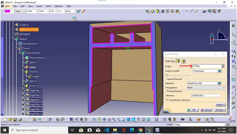
It is the angle given to the surface that makes it an inclined surface and makes it easy the removal of the core and draft. Generally, it is 3 degrees for the plastic component, 0.5 degrees for the ribs and heat stake, and 1.5 degrees for the dog house.
Prerequisites before making the tooling axes and closed surfaces
- Insure properly joined class A surfaces
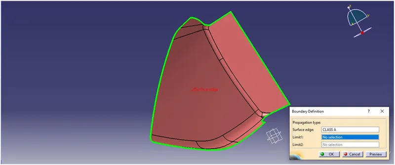
- By using the Boundary Tool check whether the boundaries are proper and insure no open surfaces in the part.
- If there are any open boundaries then use the Join tool to properly join the open boundaries surfaces.
- If possible then inform the Class A designer about irregularities in class A.
- Try to use other methods to insure proper A surface before starting tooling and closed surface. (Not recommended)
Class A surface
- Lower Substrate
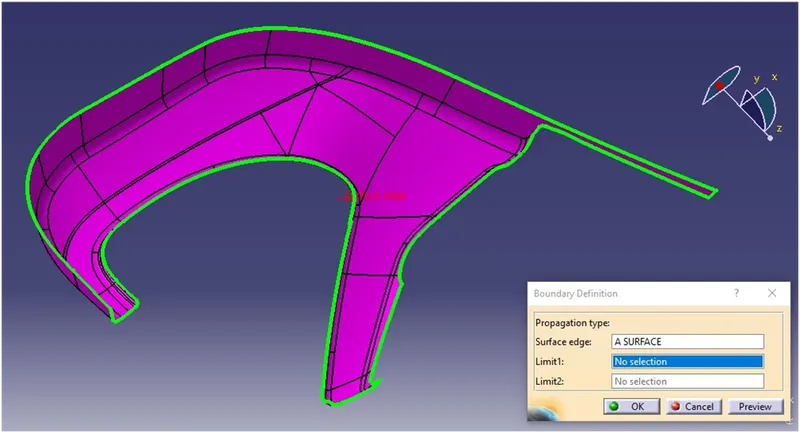
By carefully analyzing the A-surface of the lower substrate with the help boundary tool we do not find any open boundaries or edgy surfaces so it is a good surface to work.
- Arm Rest
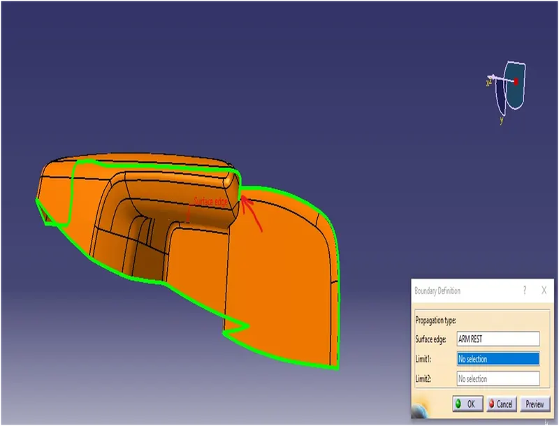
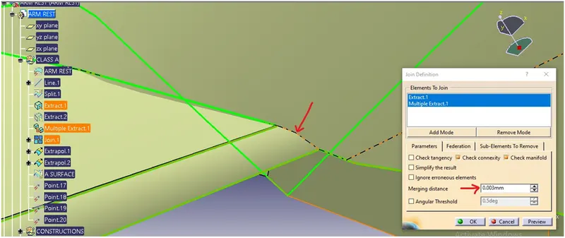
By observing with the Boundary tool we find that the outer flange of the armrest is not properly joined with the rest of the body.
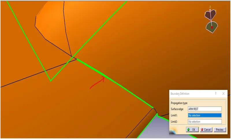
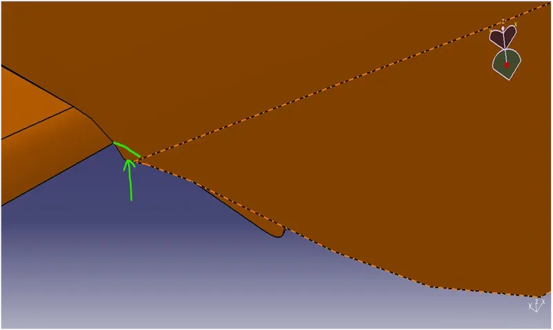
So there are two issues in the class A-surface
- The open boundary on the class A surface.
- The edged outer surface cause problem while extrapolating.
Actions (We do not recommend any action to solve class A surface problems, give the advice to go to A surface designer, but to solve our problems here we are going to solve them on our own.)
- Using the split option to split the extra edge from the class A surface.
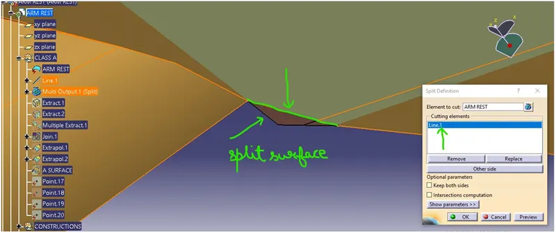
- Using the join tool to properly join the A surface and obtain the proper new A surface.
 New class A Surface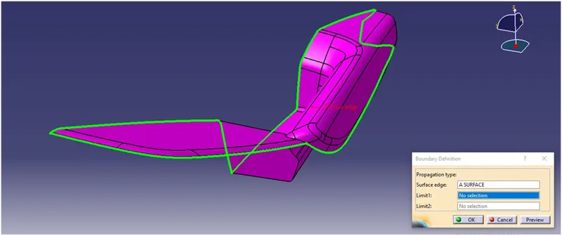
- Map Pocket
- Bottle Holder
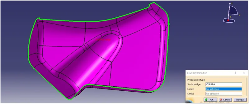
Now all class A surfaces are inspected and we are ready for the formation of the tooling axis, B surface, C surface, and Closed body surface.
Tooling Axis
It is the direction along which the mold opens for easy ejection of the solid part.
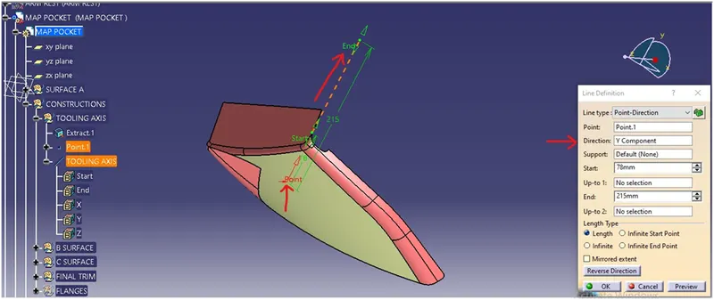
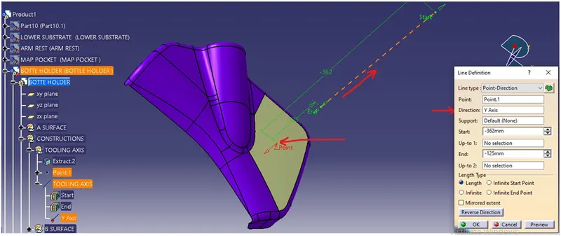
In this challenge, by observing the master we are going to make a tooling axis with a point and direction method using the global tool using compass direction(X, Y, and Z direction).
- Selecting the surface along which we need to create the tooling axis.
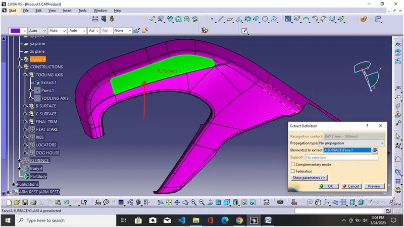
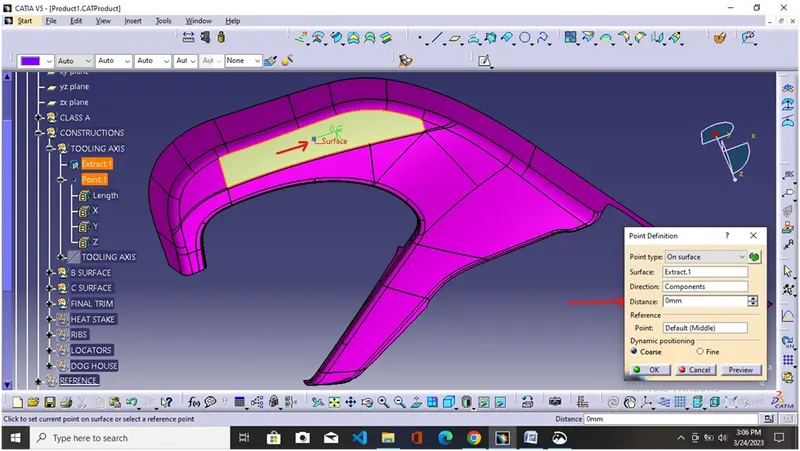
- Creation of point using the point tool using the option on the surface. Select the extracted surface and give 0mm in the distance option to create the point in the middle of the surface.
- Creation of the required tooling axis using the line tool and selecting the point and direction option to give extracted surface in the reference surface option and the previously created point in the reference point option and obtain the required tooling axis.
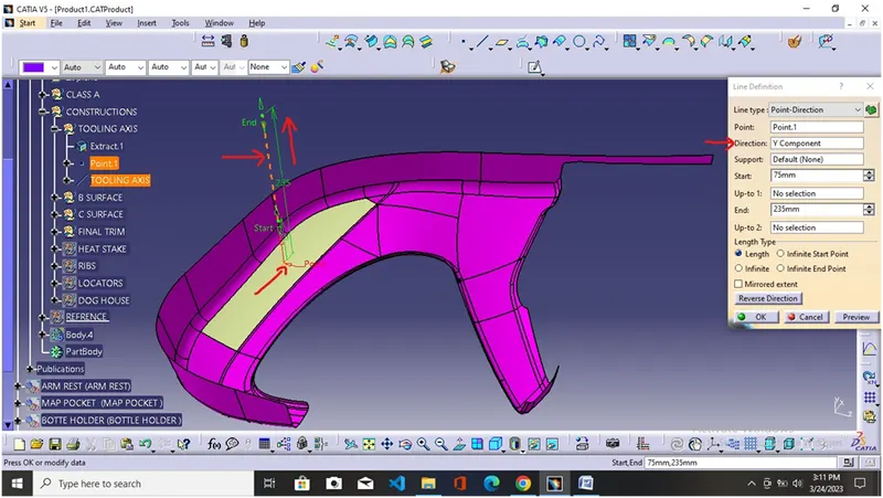
-
We repeat the same steps with other components for the formation of other tooling axes.
- Selecting the surface along which we need to create the tooling axis.
- Arm Rest
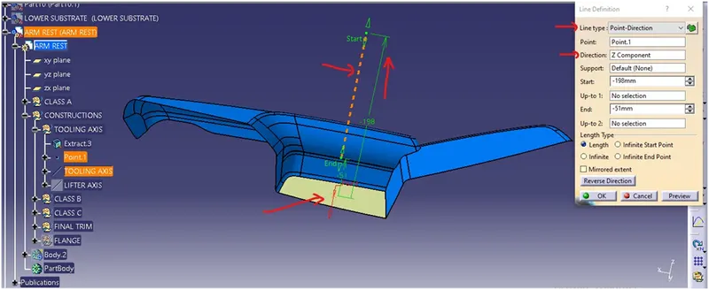 As there is a cavity or depression part in the Arm Rest and the whole part does not clear with a single tooling axis we need another tooling (lifter axis) as well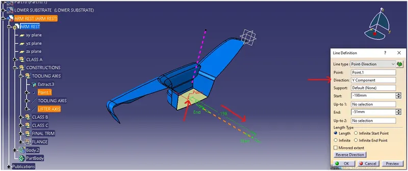
- Map Pocket
- Bottle Holder
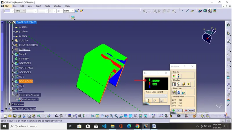
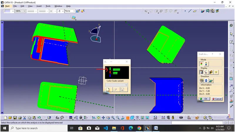
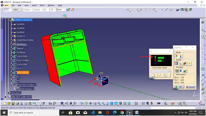
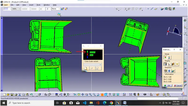
Draft analysis
It gives us information about the parts which tells us which part clears the mold walls easily so as to minimize the machining process in the finished product and final product ejected easily and minimize the contact between the product and mold walls.
-
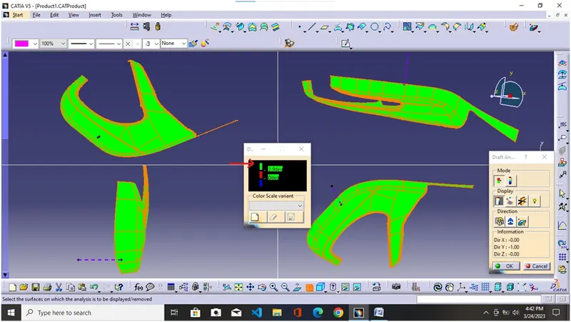
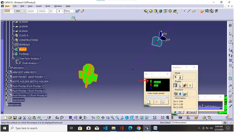
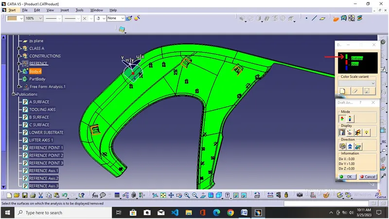
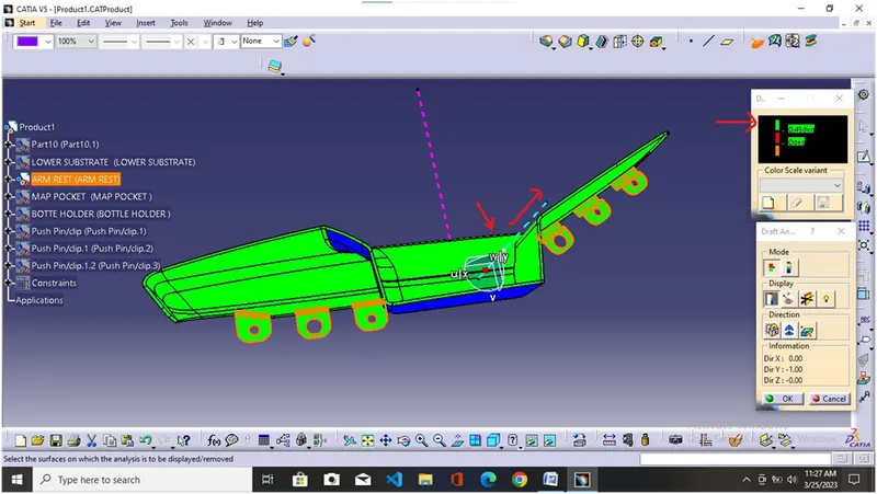
Select the Feature draft analysis tool and move the compass to the tooling direction and align the compass w axis to the tooling axis. After aligning the compass with the tooling direction again click the compass tool to insure the proper alignment of the w-axis with the tooling axis. After the proper alignment uses the locking tool to lock the compass with the tooling axis.
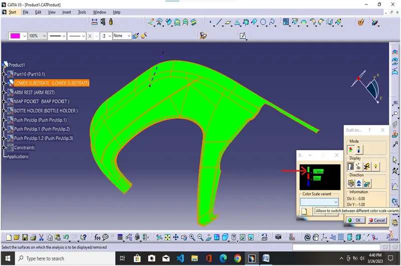
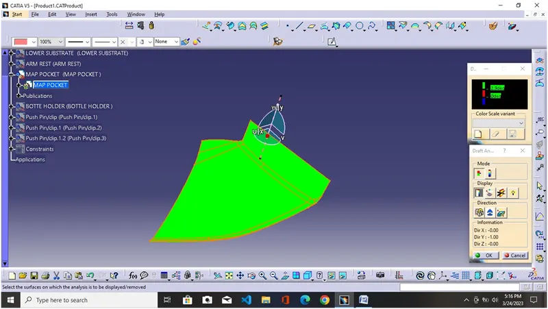
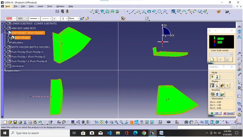
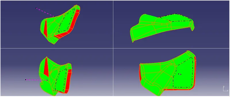
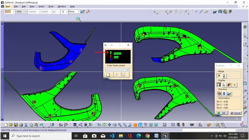
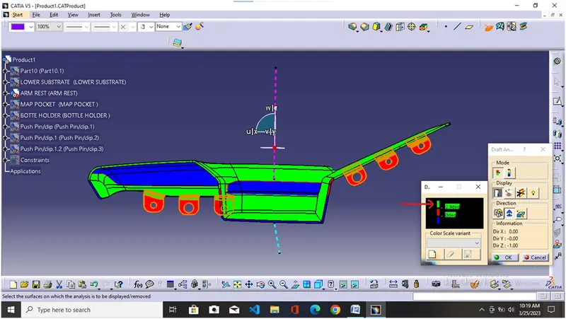
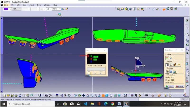
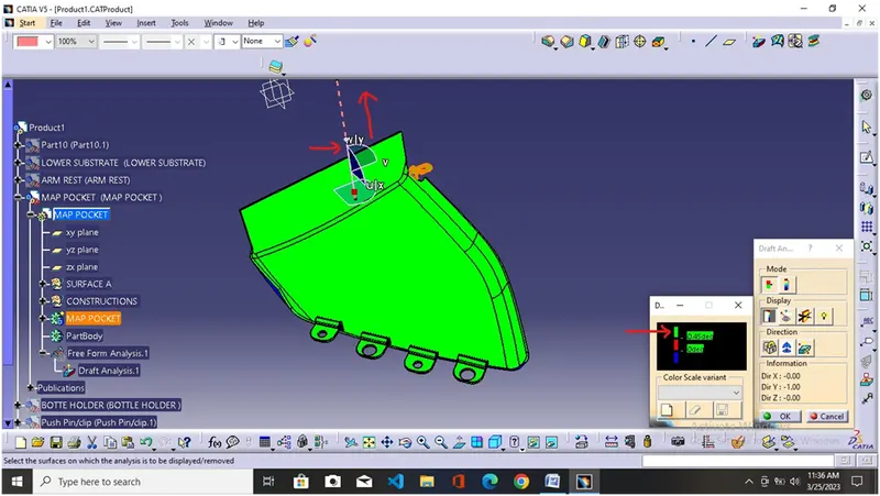
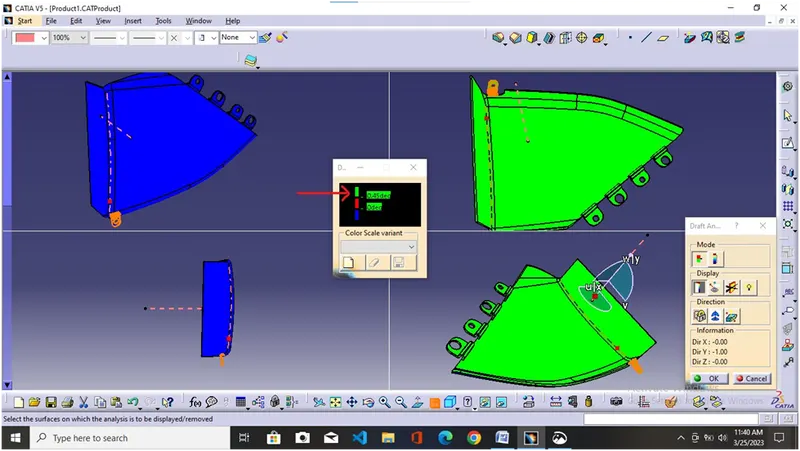
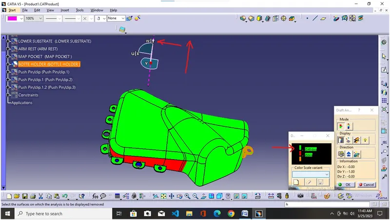
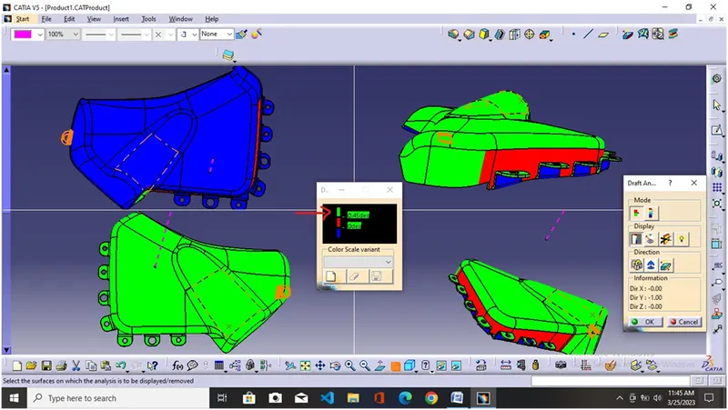
- Click anywhere on the A surface to generate the draft analysis report and use the quick analysis mode option to see the color code values where the green color defines the parts which have a draft angle greater than the green color code value generally it is up to 3 degrees in values. The red color gives information about the parts which have angles between 0 to up to a green color value which is generally up to degrees. The blue color gives information about parts that have an angle less than the red color. If A surface comes out in green color means our tooling axis is perfect and we are ready to go for the formation of B and C surfaces.
- Lower Substrate
- Arm Rest
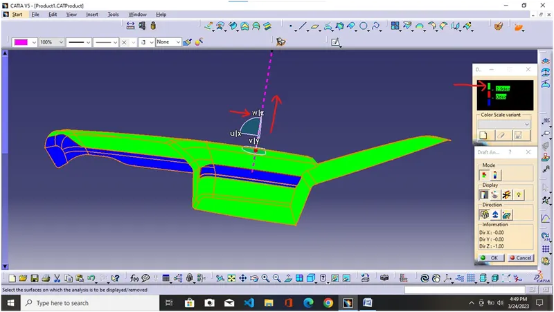 Here we see that some surfaces of the Arm Rest do not clear we can inform the class A designer to improve the A surface which serves as our input.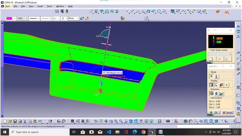
Here the angle in blue color represents the draft given to the input surface with respect to our tooling axis being in the inverse direction and asking the class A designer to improve the surface.
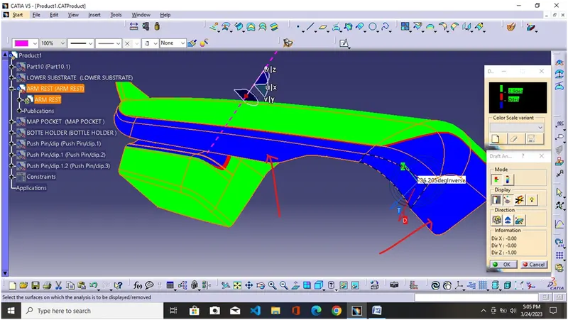
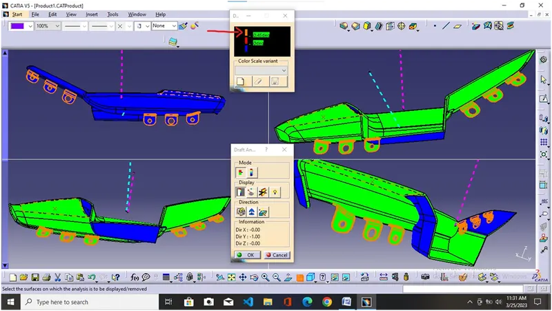
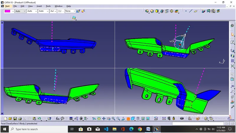
Some other backside surfaces do not clear with the main tooling direction we need to create separate tooling axis and make those surfaces clear with that axis.
Lifter Axis
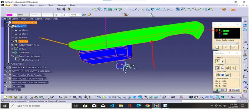
Here we see that draft analysis along the lifter axis completely clears with the back side surface.
- Map pocket
- Bottle Holder
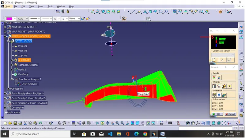 Here the angle in red color represents the draft given to the input surface with respect to our tooling axis in zero degrees and asking the class A designer to improve the surface.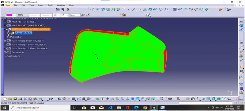
B Surface
It is the surface that is offset from the class A surface to distance to the measured thickness and it also serves as the surface which seats the engineering side feature. It is a surface that is not visible to the user.
- Lower Substrate
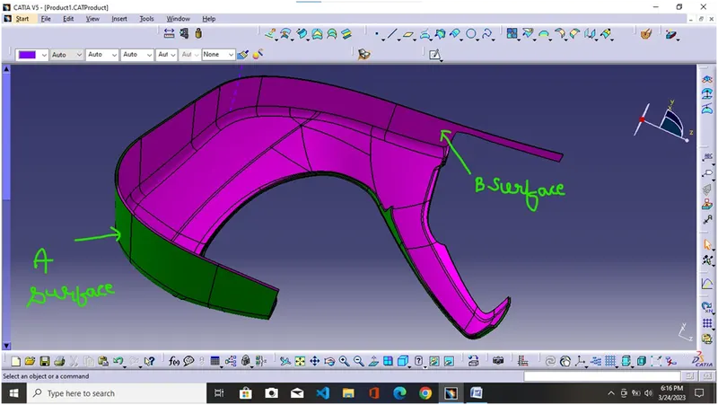 The surface which is in purple color is a class B surface while the green color is an A surface.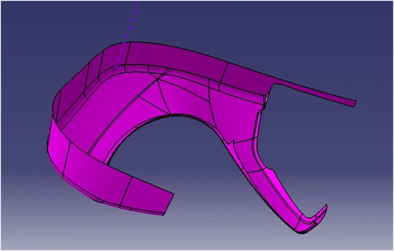
- Arm Rest
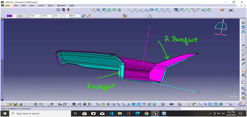
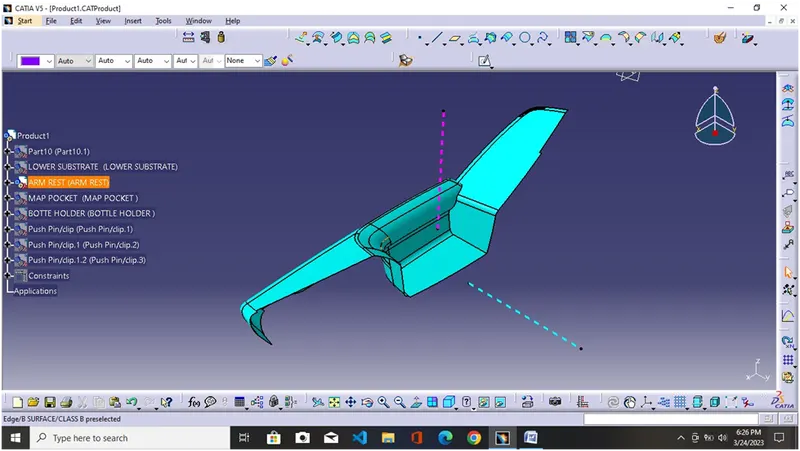
The surface which is purple color is a class A surface while the Blue color is a B surface.
- Map Pocket
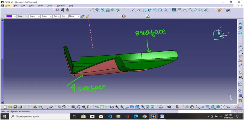 The Surface which is pink color is a class A surface while the green color is a B surface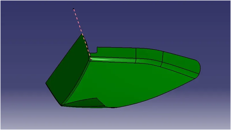
- Bottle Holder
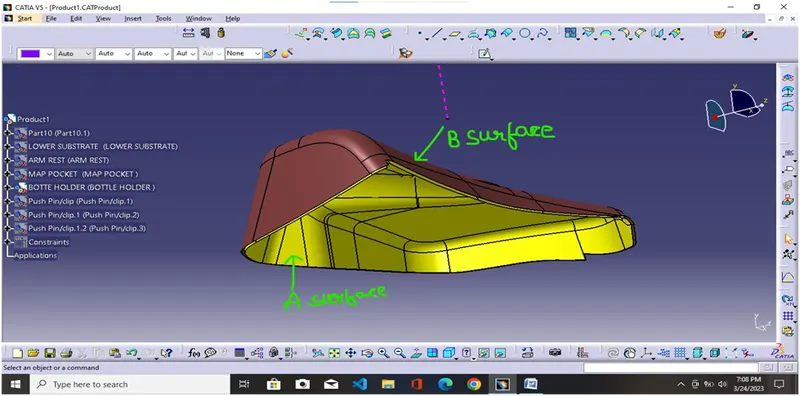 The surface which is yellow color is a class A surface while the brown color is a B surface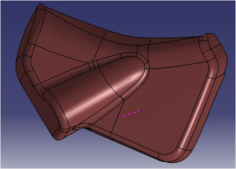
C surface
It is the joining surface that serves as a bridge between the class A surface and the class B surface thickness of this depends upon the thickness of the product.
- Lower substrate
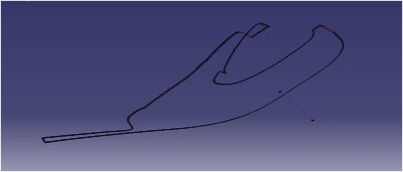
- Armrest
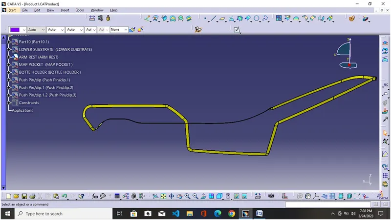
- Map Pocket
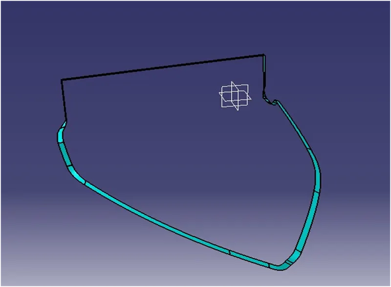
- Bottle Holder
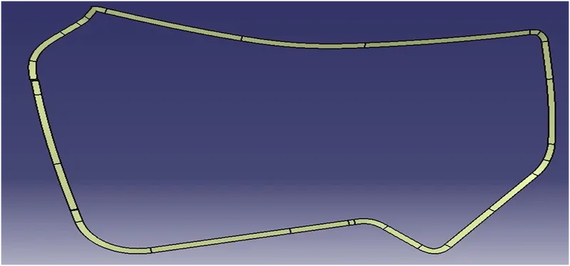
After the formation of the B and the C surface, we finally trim or joined them with the A surface to form the required closed surface after that, we can use the close surface tool in the part workbench to make the plastic component into the solid one.
Solid surface
- Lower Substrate
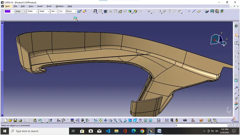
- Arm Rest
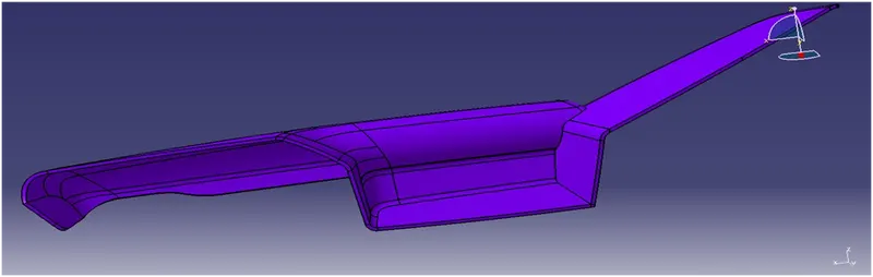
- Map Pocket
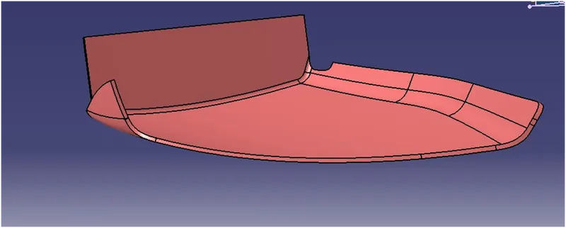
- Bottle Holder
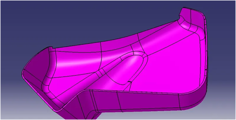
Draft analysis of solid parts
Here the steps are the same as we do above in the case of the class A surface
- Lower substrate
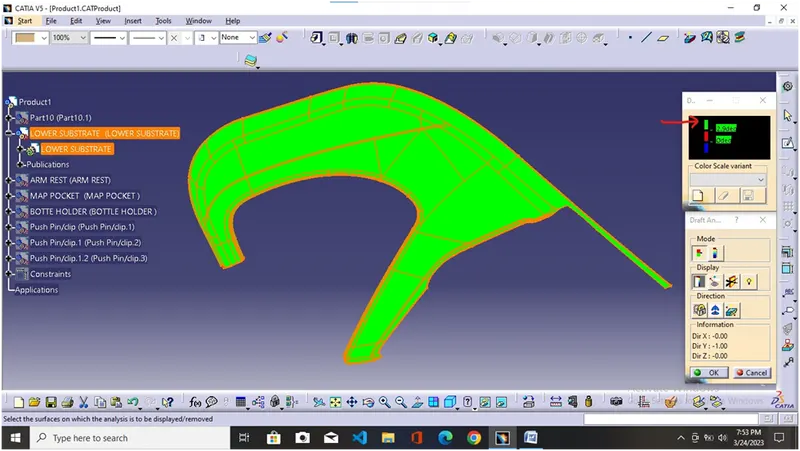
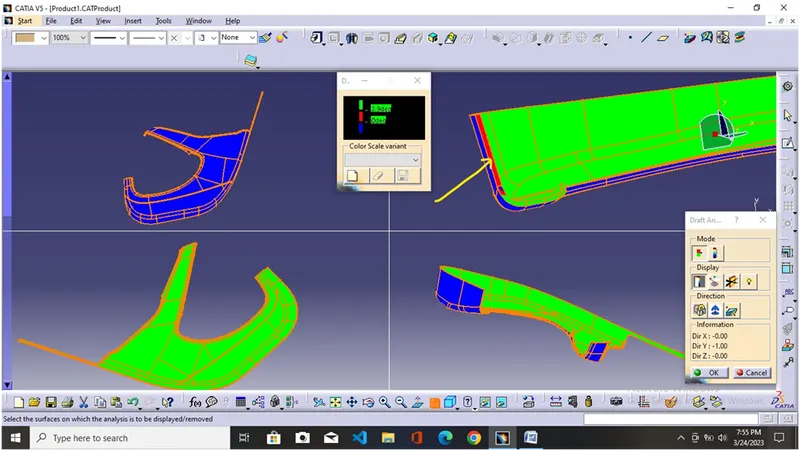 Small portion of the c surface does not clear with the draft analysis in order to make the C surface proper with respect to the A surface
 - Arm Rest
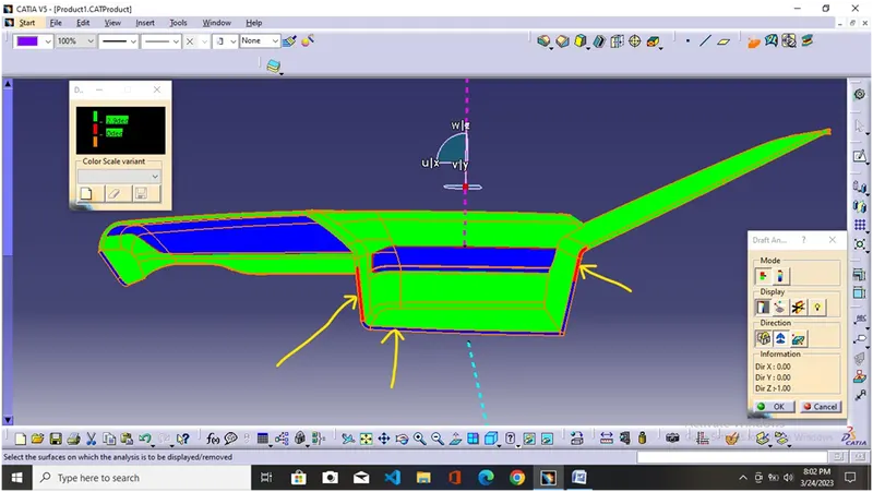
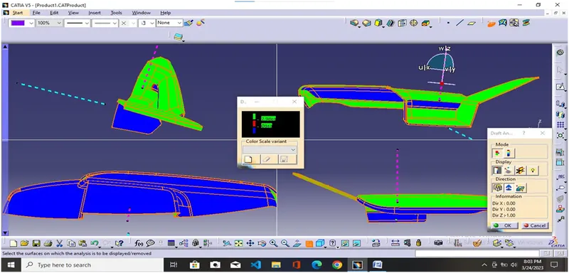 Some of the C surfaces here also do not clear with draft analysis reason is the same as mentioned above in the lower substrate part.
 - Map Pocket
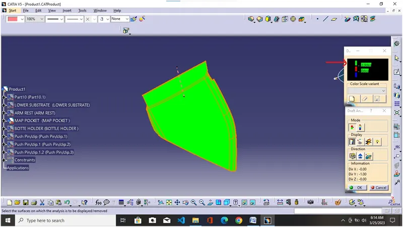
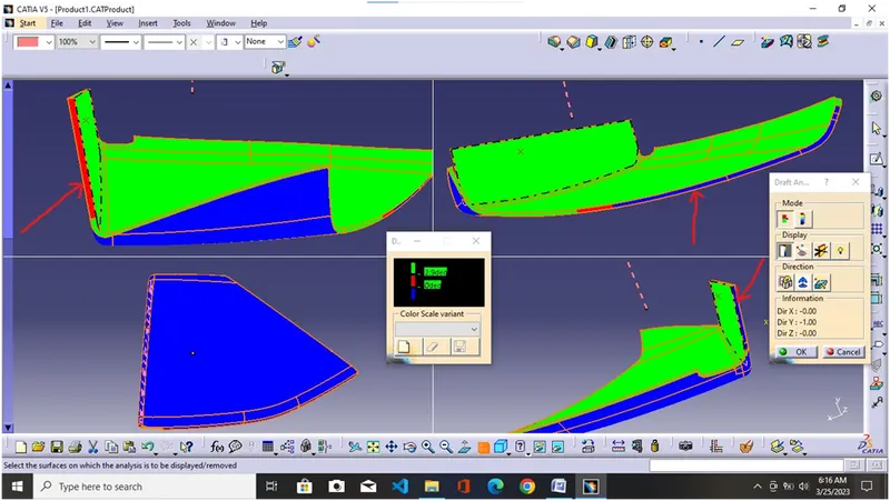 Some of the C surfaces here also do not clear with draft analysis reason is the same as mentioned above in the lower substrate part.
 - Bottle Holder
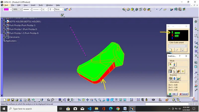
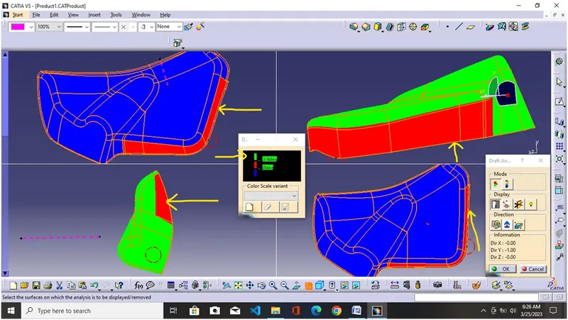
Some of the B surfaces do not clear the draft analysis test because the original class A surface also does not clear with draft analysis.
Heat Stake
It is a component used for joining the two different components using a process of heating and cooling the temperature of plastic components known as heat staking.
Rules for making heat stake
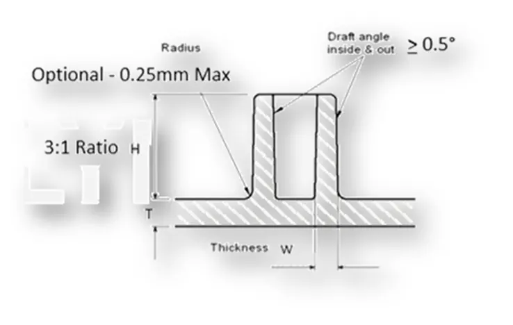
By using the master section given as input we use that input to extract dimensions for the construction of the heat stake and other engineering features.
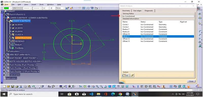
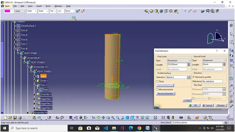
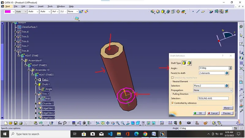
While giving the draft angle as 0.5 degrees to the outer and inner surface of the heat stake so that it makes it clear with the draft analysis. While giving the distance between the two heat stakes around 50mm along the curve.
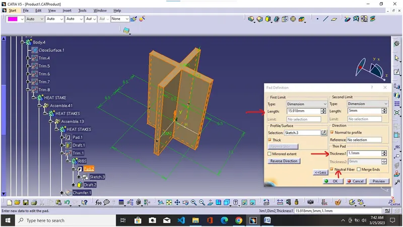
Ribs
These are used to give extra strength to an existing component without increasing the thickness of the material.
Rules for making Ribs
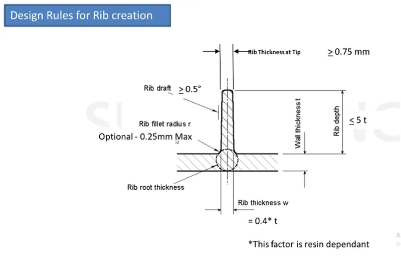
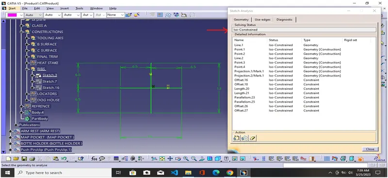
While for the proper seating of flanges on the ribs as per the master section we increase the length and thickness within the design limitation to avoid sink marks and follow as much as possible master section.
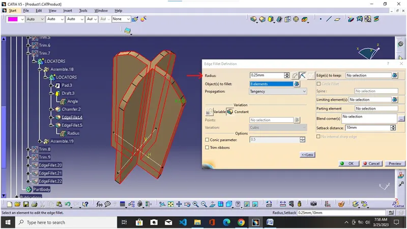
Locators
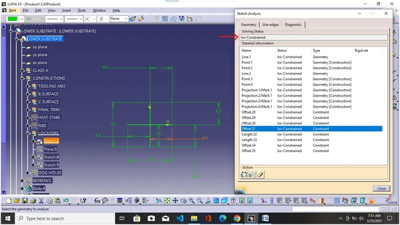
Locators are used for the proper assembly of two components while used as an arresting component which arrests the degree of freedom of two components and allows only the constraint motion between two and desired outcome is obtained.
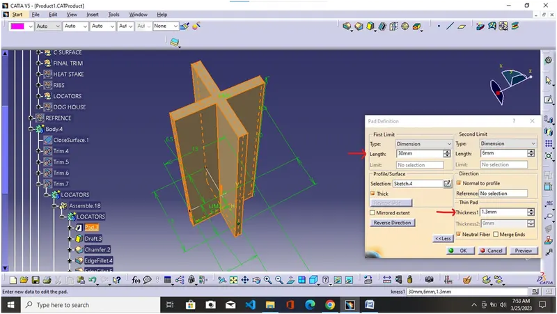
Adding 5mm to the height dimension above the heat stake.
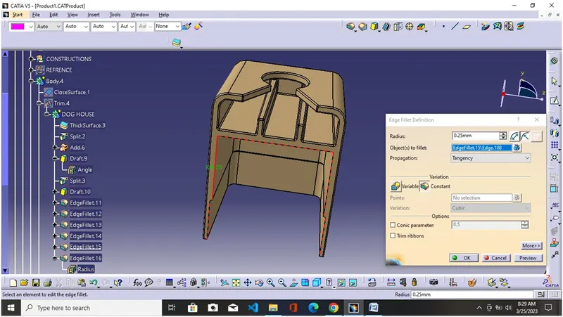
Dog House
This engineering feature is used for the seating of other engineering features and provides height without making sink marks and other plastic defects on the A surface.
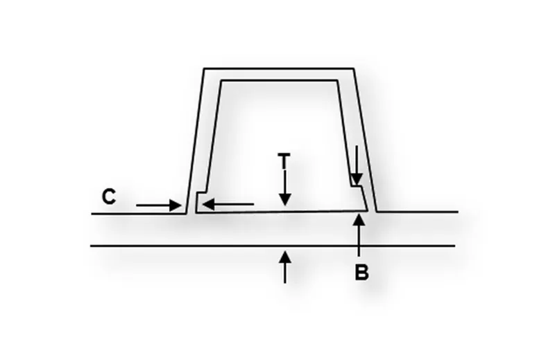
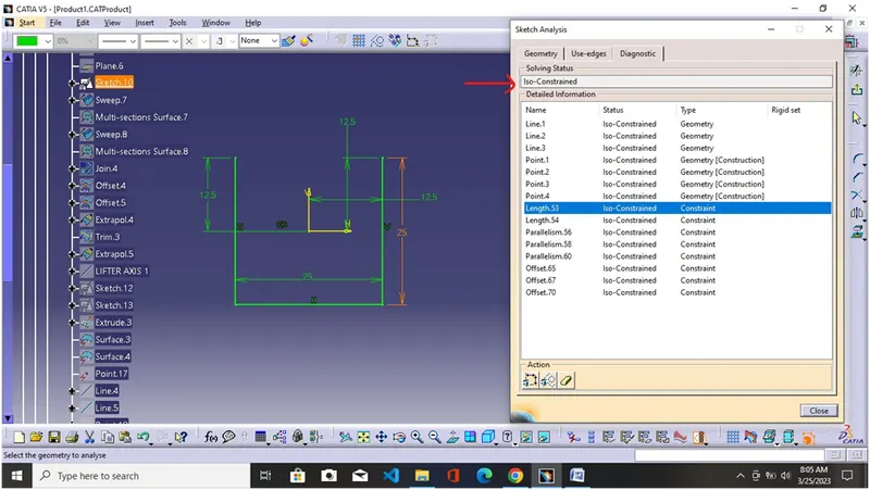
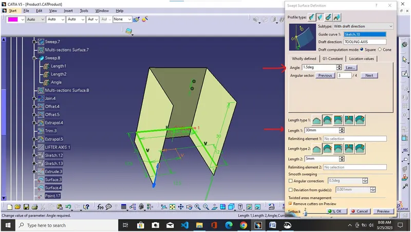
Providing 1.5 degrees to the outer surface while using the sweep tool on the dog house to achieve the desired draft angle
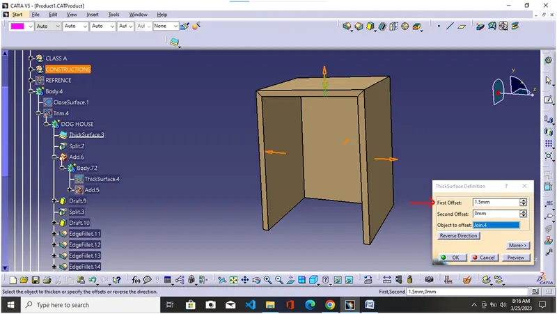
Lifter Axis
This is the axis used for the draft analysis while clearing the inner surface of the dog house. Providing 0.5 degrees to the inner surface will achieve the desired degrees for the proper ejection of the core and cavity without distorting the inner surface.
While arranging the Dog house always tries to keep the gap between the front face in the direction of the lifter axis is 90mm for the easy removal of the core while traveling in the direction of the lifter axis.
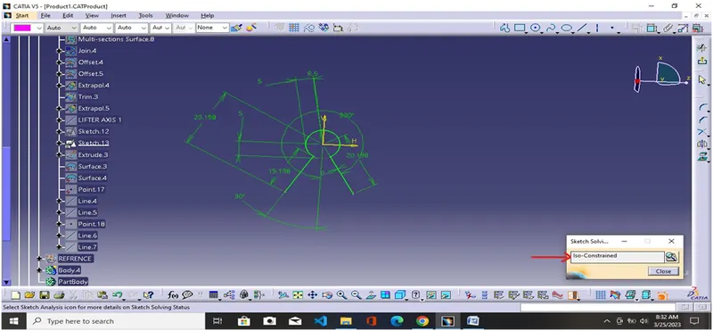
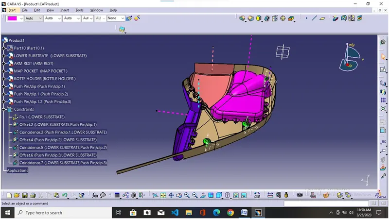
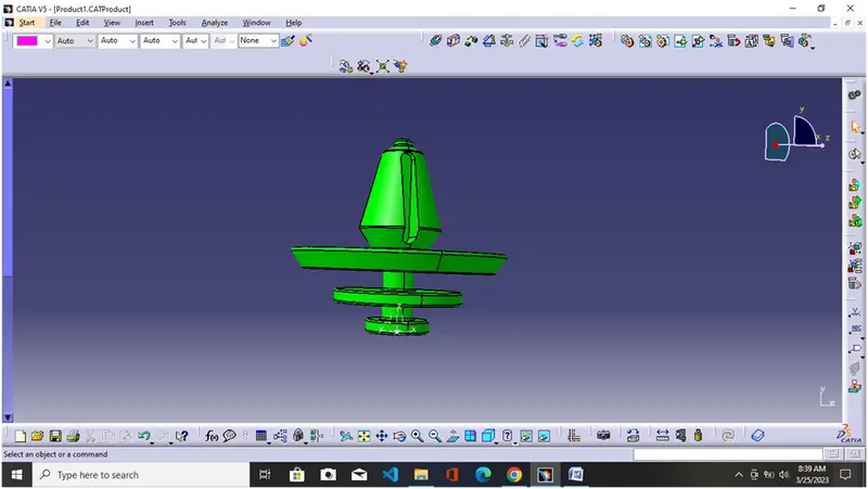
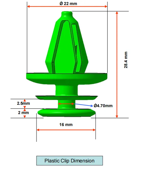
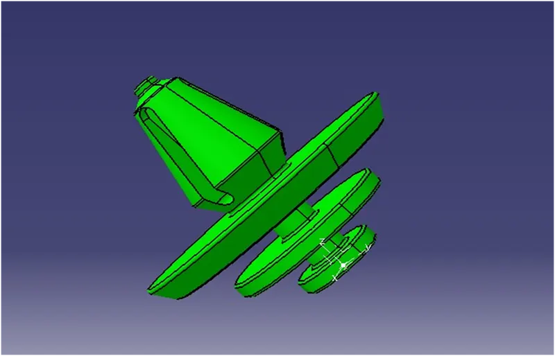
Push Pin
Push pins are a popular mechanical attachment because they provide flexibility and dependability at a low cost. Flexible design. Hole location and attachment forces can be customized for each specific application.
Draft Analysis of engineering features
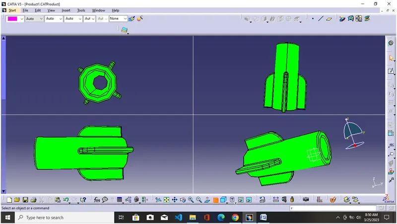
Heat Stake
Locators
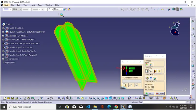
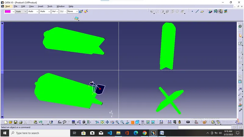
Dog House
Draft Analysis of the final component
- Lower Substrate
- Arm Rest
(Along the main tooling axis)
-
(Along the Lifter Axis)
- Map Pocket
- Bottle holder
-
Final Product