Week 12- Final project
Development of a Door Trim Panel :
Aim:
- To Improve the Door Trim panel with given Class-A surfaces into closed surfaces with the guidance from the master section.
- Create a attachment features as per design standards .
Objective:
- To check the quality of class-A surface .
- Create a Tooling axis on the sketch and check whether perfect position for the axis placed.
- Create a B and C surfaces to form a closed Body .
- Create a Attachment features like Heatstakes ,Ribs, Locators , Dog Houses as per Design standards.
- Extract a dimensions from the mastersection to create a flange .
- In the Assembly design using Constraints to coincide the push pin with the Dog house .
Introducton:
Design overview in Automotive industy:
1)Concept sketch
2)Styling class-A
3)Feasibility check
4)Concept validation
5)New product design
6)Development
7)Proto built
8)Design validation
9)Pilot production
10)Mass production
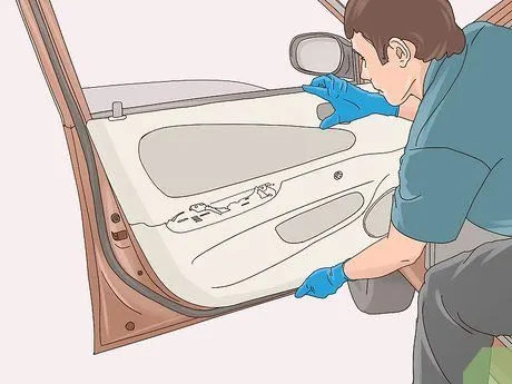
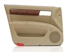
- Door trim panel is a front face for the Biw panel of door .
- it is used to create a many specified items to be placed on that surface with technical purpose and customer comfort.
- Inthe technical aspect we can arrange the power windows switch and speaker and styling the interior .It is used to hide the all wiring components are we provided.
- In the customer aspect to place a hand on arm rest in the Driving and also for passengers .
- place a bottles on the bottle holder their is a small shelf to put a books and snacks ont that shelf side of bottle holder.
Method:
We have a four parts
- Arm rest
- Lower substrate
- Map pocket
- Bottle holder
Commands are used inthe project:
- Sketch work bench , part work bench ,. surface work bench , Assembly work bench.
- point
- poistioned sketch
- operations, profile,sketch tools,constraints in sketcher work bench
- in the part work bench
- sketch based features, Dress up features, transformation features,surface based features, references boolean operations
- wireframe features, surfaces,operations,draft analysis are used in the surface work bench.
Heat stake:
- Extract the surface on the lower substrate and measure the distance of heatstake from the given master section.
- Form a point with the help of lines from the master section point was formed.
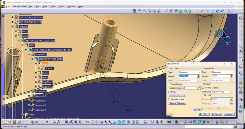
- create a plane parallel to master section take a positon sketch create a circles in differenct sketches and pad it.as reference of main tooling axis .
- Give a draft to the heat stake inner and outer with the 0.5degree with a pulling direction of tooling axis
- Do a union trim with closed surface unwanted material was removed.
- Rib :
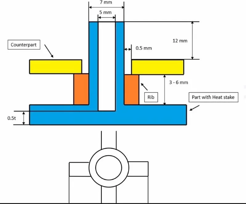
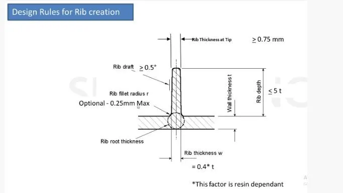
- Take a dimension from the master section and create a rib as per design standards
- thickness of rib us 0.4*T
- draft 0.5degree
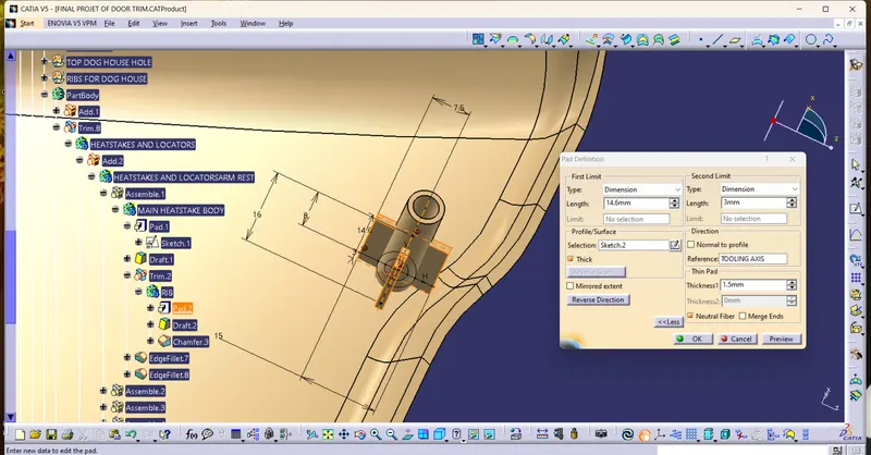
- Create a sketch take a refernces from the heat stakes and create a rib as per dimnsion and iso constrained them .
- thick the sketch with 1.5mm means given thickness is 2.5.As per standard 40% of so 1.5mm clickon neutral fiber. provide same in every direction
- Do the union trim with heat stakes and rib remove the unwnated material give draft and achamfer to the edges of rib and give a edge fillet to faces onthe surface.
- Use paste special option form the many heat stakes with link.
- use translate command to move the copies of heat stakes as per required position .
Flange:
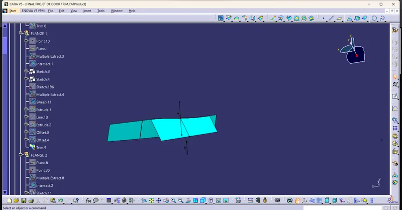
- Extract the lines from the master section and create a heat stake than intersection between the plane and the extract the surface from the final trim .line was formed.
- with the help of that create a random straight line in vertical angle that line coincide with intersect line edge and make an angle of 3degree as per master section iso constrained them.
- again draw a sketch and extract the line in master section through projection 3D elements change in to isolate increase the line in horizonal.
- take a profile as vertical sketch and guided curve as extract from the final trim extracted surface and surface was formed.
- extrude the horizontal line and trim the both surfaces and thicken the surface with 2.5mm than give a draft to the side face and front face as 0.5degrees
- fillet are given to flange as per master section front was given as 10mm and back side is 3mm ans remain edges are givn as 0.5mm
- do union trim with the closed surface than unwanted material was removed.
Dog house:
- Extract the surface from the lower substrate and create a point on that extract surface .Form a plane on that perpendicular to tooling axis .
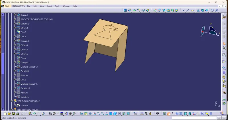
- take a positioned sketch and draw a central triangle and cosntrain them all lines are iso constrained them.and one side take as reference
- Use draft direction as 1.5 degree inthe height of 30mm and create a horizontal line and as perpendecular to tooling axis and extrude them and split them surface was formed .
- verical line was create the extrude and offset into forward direction into 12.2mm leave a space for to smoothness to split .
- Thick the surface and split with previous offset to cut the thicken the surface .
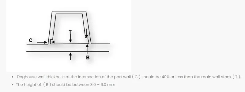
- Create a surface use previous offsets to cut the under surface with a 40% of 2.5means 1mm it is width and height of 6mm as per design standards and trim the surface and split with the thicken surface .
- given a draft to inner surfaces as 0.5degree front side as neutral face and give a edge fillets to outer surfaces and inner surfaces.
- Create a sketch for the rib base and thick the surface into 1mm and create a ribs on the base do a boolean operation of union trim with base.
- Use a previous offset to split front face to same as rib base equal to dog house face.
- give a draft to ribs as 0.5 degree and finally give a fillets as 0.25mmto the base and ribs.
- union trim with the ribs and dog house to remov ethe unwanted material and made as one body.
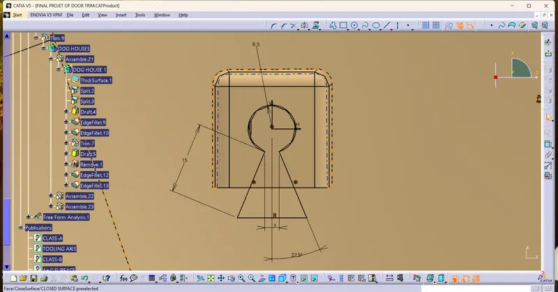
- create a top hole on the dog house to put the push opin on that 5mm radisu of the hole size and the vertical lines are draw the 15mm length and 22.5degree angle and symmetry the both lines on the both sides.
- Pad the sketch
- Do a boolean operation to remove thehole bosy from the dog house.Fianlly hole was formed onthe top surface of the dog house.
Arm rest:
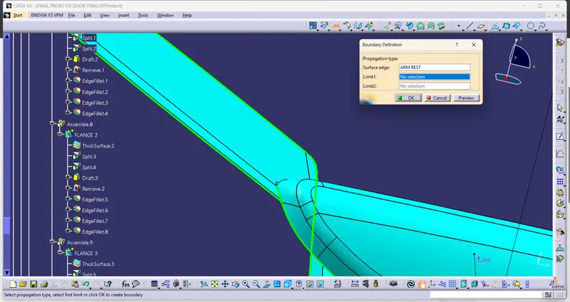
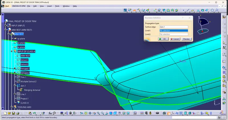
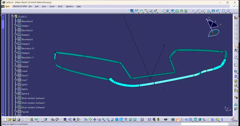
- Given class-A was pre checked by the boundary command .If any extensions or patches are occur it was displayed.
- In this detect a one error we dont have a right to update we can sent a error to class a engineer to reconstruct after he was corrcect the error again he was sent back to use we can work on it.
- As a designer we have no right to correct the mistake on class-A Upto very less mm can we correct it.
- in this diagram extract the surface of line was extend from the booundary than extraolate the both surface and trim it .
- After that surface was goes some extend so we create a line on this endpoint and another one at other endpoint project the line on the surface and split them Class -A surface is at now correct.
Class-A:
Firstly given calss-A was pre checked by the boundary command
Draft analysis of Class-A:
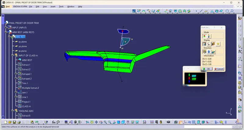
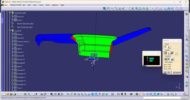
- Here draft analyis can done throgh two tooling axis one is main tooling axis is z direction construct to normal surface and another one is y direction it is side tooling axis construct through point direction .
- Generally in the industry side tooling not recommended because it is increased the manufacturing cost of the product .
Class-B with patches:
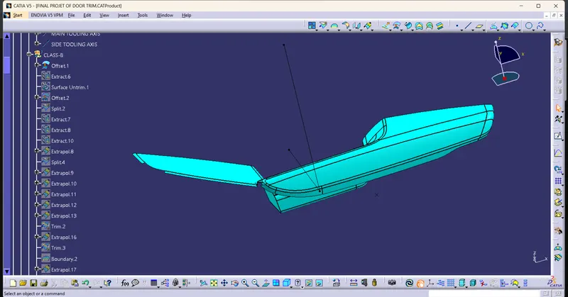
- After we offset the surface take the value from the master section so we got 4 patches from the offset
- patch -1 we can extrapolate the line and trim them with the surface
patch -2:
extract the surface from the class-a than untrim the surface offset as parallel to B surface than split with the the edges of the B surface gap was filled .
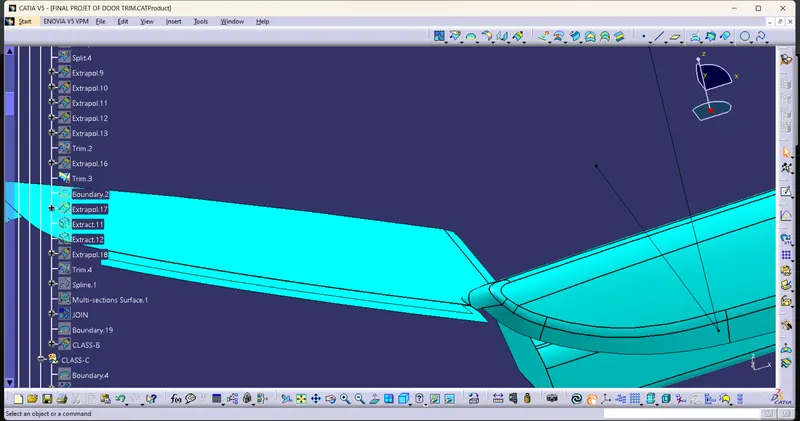
Patch-3:
we can extrapolate the patch-1 and patch 2 extraolate than trim them .
extrapolate theupper surface and extract it and than extract the lower surface and extrapolate them than trim it
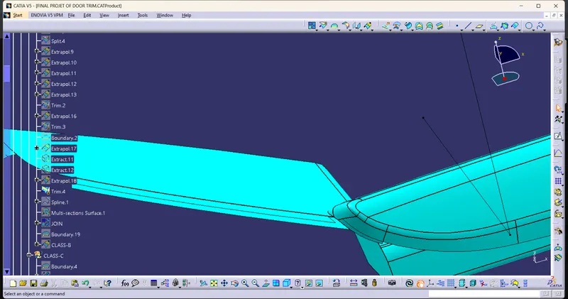
patch-4:
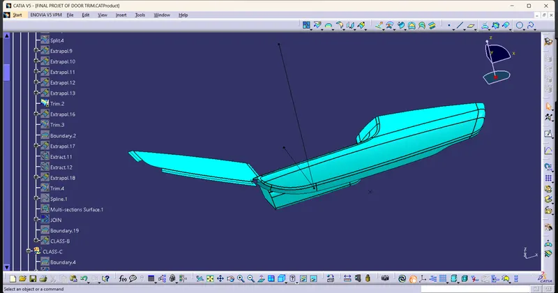
create a spline onthe left side wing we can see onthe below image than do a multisection surface to create surface onthe patch and finalljoin all the patches as one surface.
Before pathces fill:
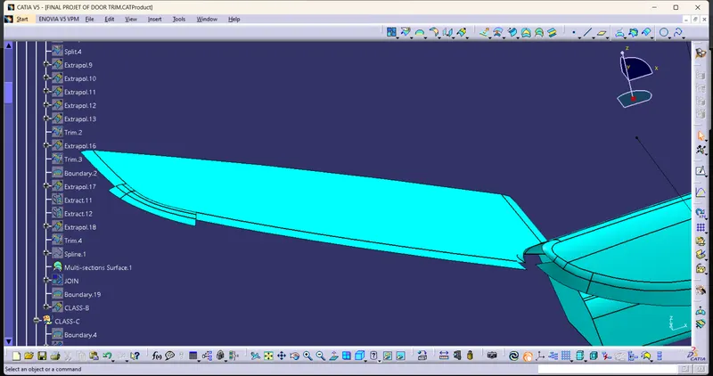
After reconstruct the pathces of Class-B:
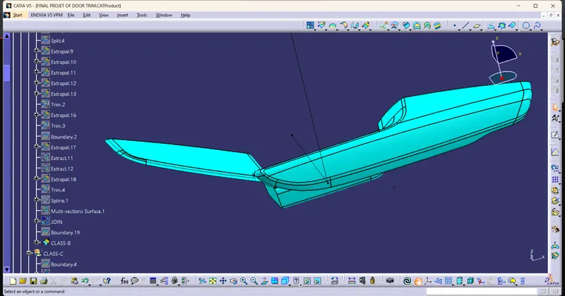
Class:c
- Take A surface boundary as reference to construct the C surface.
- Class-A nd Class-B sides of the surface are parallel to tooling axis so we have take a sweep of reference surfaceof 90Degree thanonly intersect the C surface with B surface.
- Class-A nd Class-B sides of the surface are perpendicular to tooling axis so we have take a draft direction with 3Degree thanonly intersect the C surface with B surface.
- in the process some edges and curves are not form with good quality so we have to do a multisection surface at that surface we get quality surface at that position.
- Finally edges of the sweep are not connecte we can extrapolate the edges and trim them at last use join command to joinall the sweeps and multisection as one surface.
A+c : join Class-A with Class -C than trim with B-surface finally form a Final trim surface .
check with boundary command if their any gap in between onthat surface.If not than use part wok bench command of closed surface convert into surface into solid body
Draft analysi with main tooling axis:
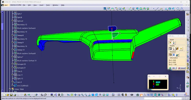
Draft analysis with side tooling for closed surface:
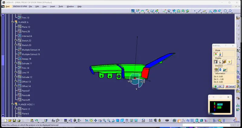
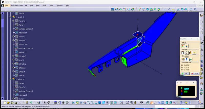
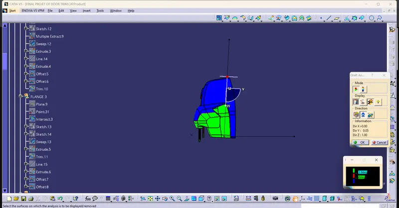
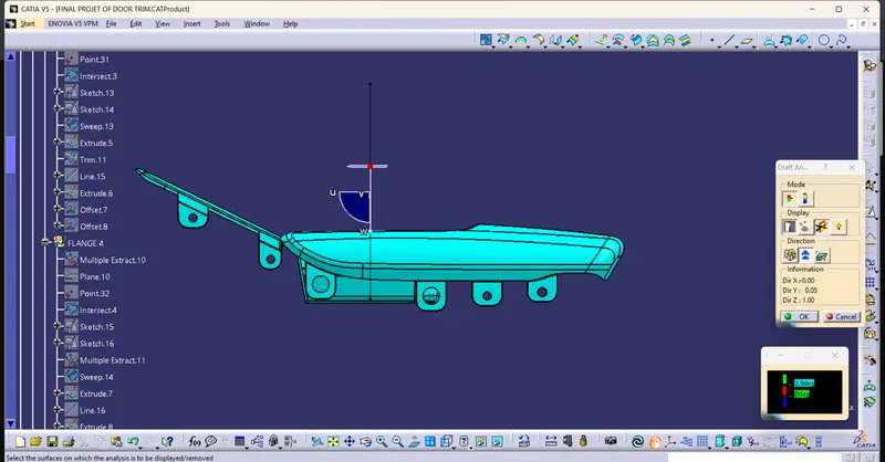
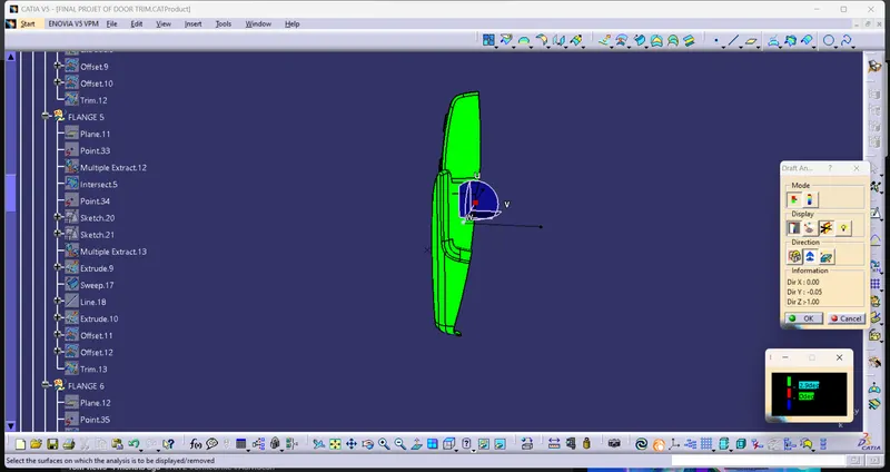
Draft analysis main tooling:
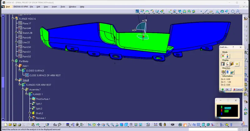
Drafting analysis for flanges with Side tooling :
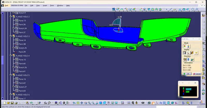
Flange:
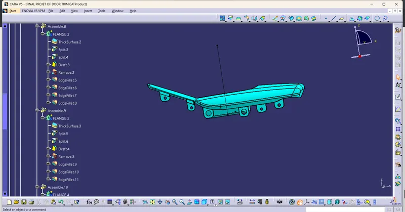
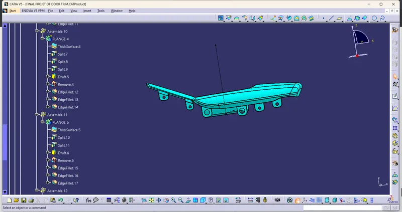
Flanges Draft analysis:
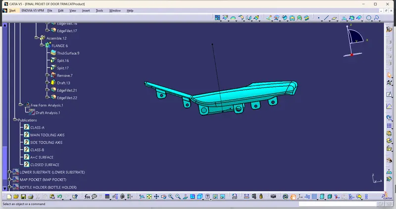
Lower substrate:
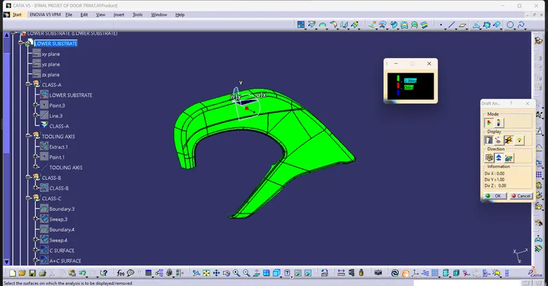
Class-A:
- pre checked the surface with boundary command their isno patche so we can go for a tooling axis.
- Here we use compass to check the part which direction is visible to all portion so here it is y direction extract a surface place a point draw a line according to Y direction.
- here we did draft analysis with 3degree it was satisiifed.
Class-B:
- offset the class-A into downward so their is no patches.
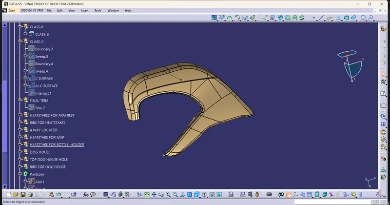
Class-C:
- here we Class-A and CLass B is parallel to tooling axis so we go to reference surface sweep with 90degree and construct the surface into many sweeps not as single sweep than only good quality surface.
- Join A surface iwth C surface than trim with B surface
- check with boundary command if their any gap in between onthat surface.If not than use part wok bench command of closed surface convert into surface into solid body
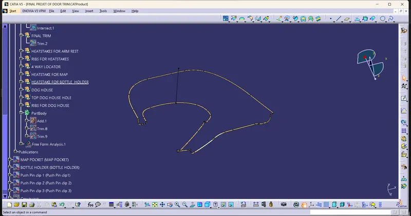
Closed surface:
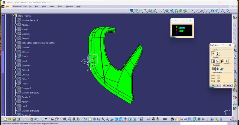
- Draft analysi with 2.9degree it is satisfied
Dog house:
Draft analysis through side tooling axis:
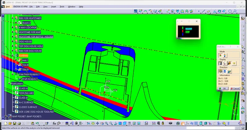
Heat stake:
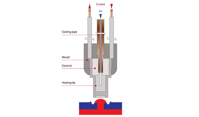
Heat staking machine:
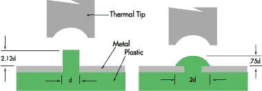
Heat staking also known as thermoplastic staking is the process of joining two dissimilar materials together. In heat staking we use local heating and cooling to raise the temperature of plastic components and allow plastic reforming to be carried out.
After creation of heat stakes using this machine placed onthe heat stake heat was generated on the ceramic. through rhi s current pass through due to that heat generated under the heating tip chamber plastic was metlt into the die shape of the machine.
It was connected to flange than act as a lock between the parts with moving
process:
Locator:
3-2-1 PRINCIPLE:
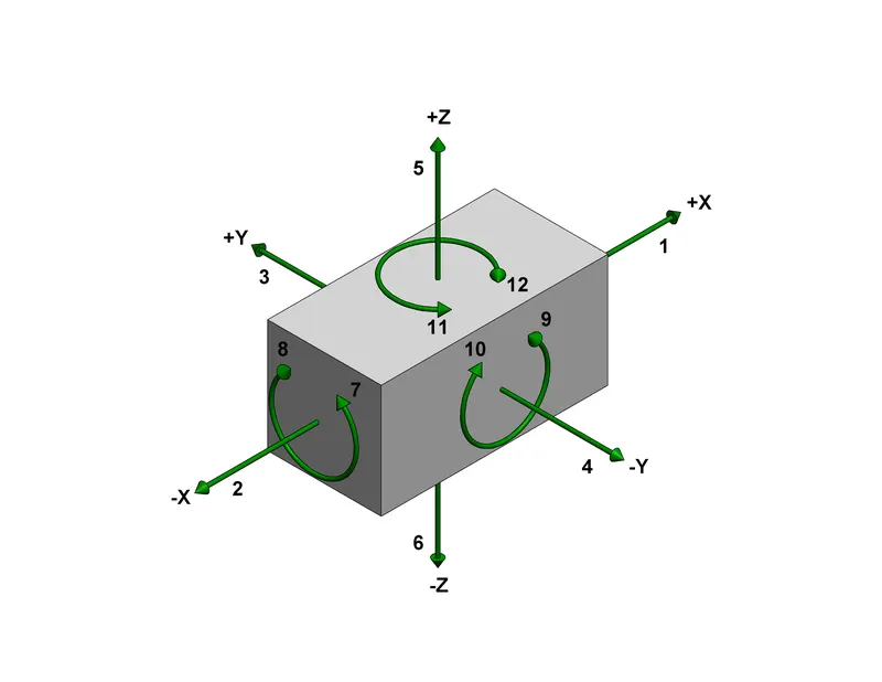
A work-piece free in space can move in an infinite number of directions. For analysis, this motion can be broken down into 12 directional movements or "degrees of freedom". All 12 degrees of freedom must be restricted to ensure proper referencing of a work-piece.
As shown in below diagram, the 12 degrees of freedom all relate to the central axis of the work-piece. Notice the 6 axial degrees and 6 radial degrees of freedom. The axial degrees of freedom permit straight-line movement in both directions along the 3-principle axis shown as X, Y & Z. The radial degrees of freedom permit rotational movement, in both clockwise & counter clockwise radial directions around the same three axes.
Thsi locator are use to control the degree of freedom A round locating pin located concentrically in a hole is a common application of a 4-way pin, and helps to further secure the piece. 4-WAY LOCATORS: 4-way mean you prevent movement at 2 axes (+X, -X, +Y and -Y) on the plane.
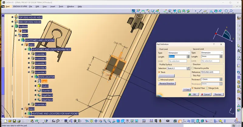
- Locator height is more than the heat stake so here heat stake is 25mm than we construct the locator adding 5mm more means 30mm height of the locator
- Extract the surface and create a point as middle than select a plane as parallel through point than take a positone sketch create a lines of 15mm in horizontal and 16mm vertical axis and constrained them .
- use thick command to thicken the lines as 1.5mm as neutral fiber.
- Give a draft to all faces as 0.5 degrees neutral axis as plane pulling direction is tooling axis .
- Use Chamfer to edges of a locator as 2mm and 45degrees.
- Select the faces and eddges of a locator and fillet them .
- Copy the locator body and define in part body paste as special use translate command to translate the duplicate locator in the desiresd location .
- Add this two locators in one body and union trim with main part body.
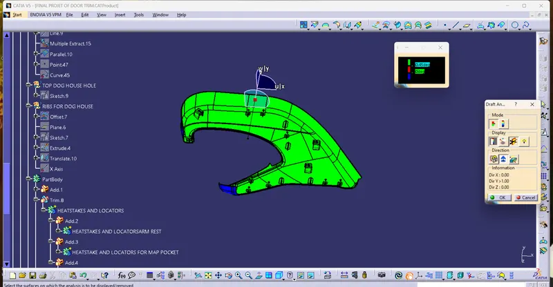
- Final draft analysis was done with 0.45 to 0.49 degree it was satisfied
Draft analysis for attach ment features:
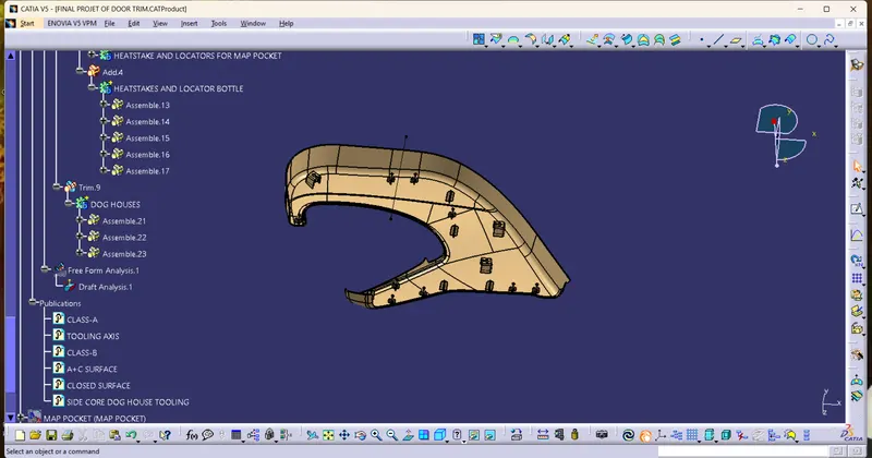
Publications:
It was plays major role to identify the part inthe diagram it is hard to identify inthe tree structure so it is make easy to find.
Map Pocket:
Class-A:
- prechecked the class-A surface with boundary it was shown any errors inthe class-A surface
- Tooling axis was created through compass viewing in y direction part was major portion visble so we take y direction as tooling axis.
- so do a draft analysis onthe Class-A with 3degree itwas satisfied.
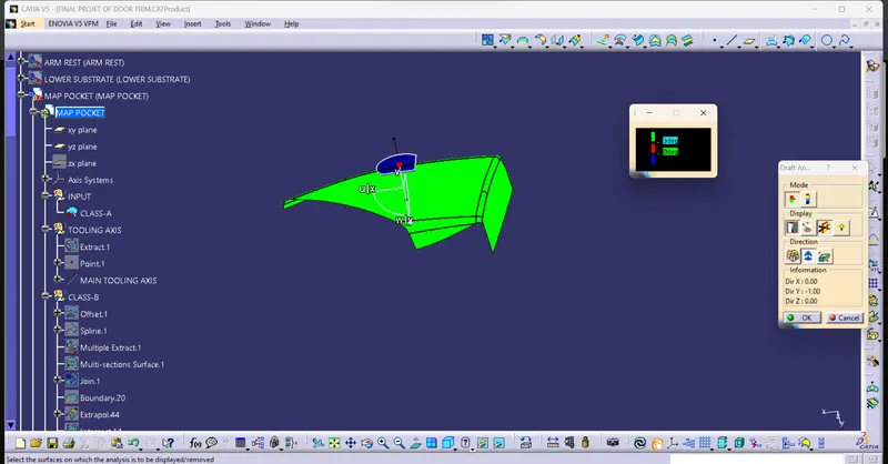
Class-B:
After offset the Class-A in downward than we found a patch on the surface.
Patch of class-B:
- Create a spline on that faces to connect then use multisection surface to fill that surface than join them .
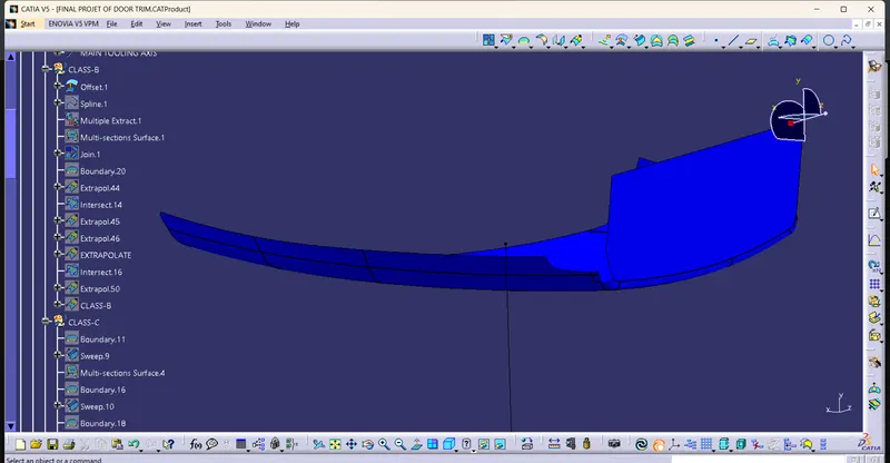
After the update of class-B:
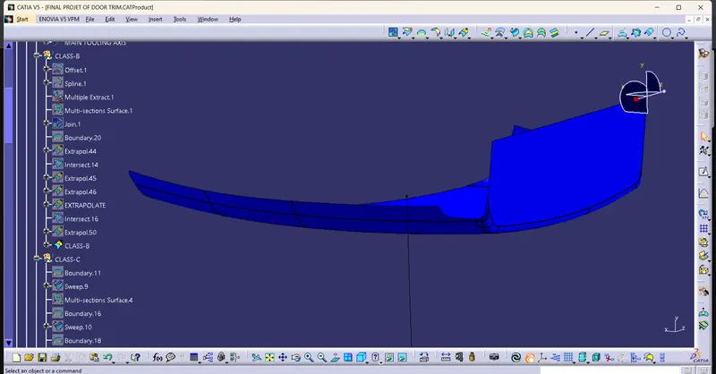
Class-C:
- Take A surface boundary as reference to construct the C surface.
- Class-A nd Class-B sides of the surface are parallel to tooling axis so we have take a sweep of reference surfaceof 90Degree thanonly intersect the C surface with B surface.
- Class-A nd Class-B sides of the surface are perpendicular to tooling axis so we have take a draft direction with 3Degree thanonly intersect the C surface with B surface.
- in the process some edges and curves are not form with good quality so we have to do a multisection surface at that surface we get quality surface at that position.
- Finally edges of the sweep are not connecte we can extrapolate the edges and trim them at last use join command to joinall the sweeps and multisection as one surface.
A+c : join Class-A with Class -C than trim with B-surface finally form a Final trim surface .
check with boundary command if their any gap in between onthat surface.If not than use part wok bench command of closed surface convert into surface into solid body
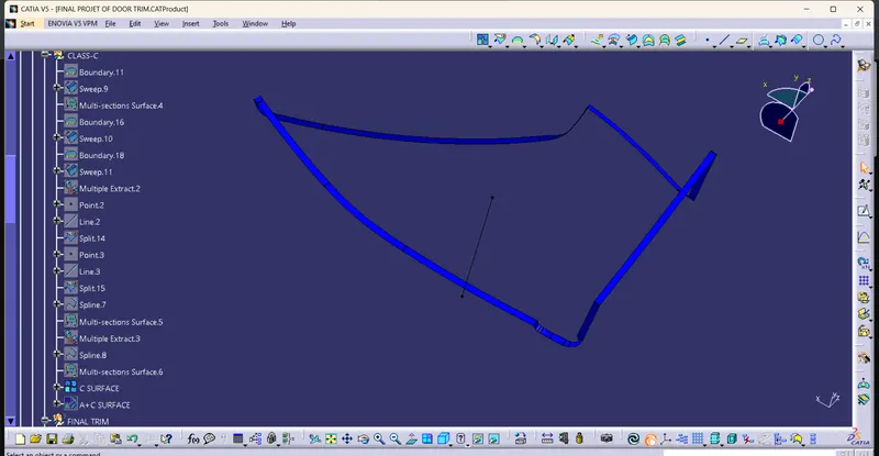
Closed surface:
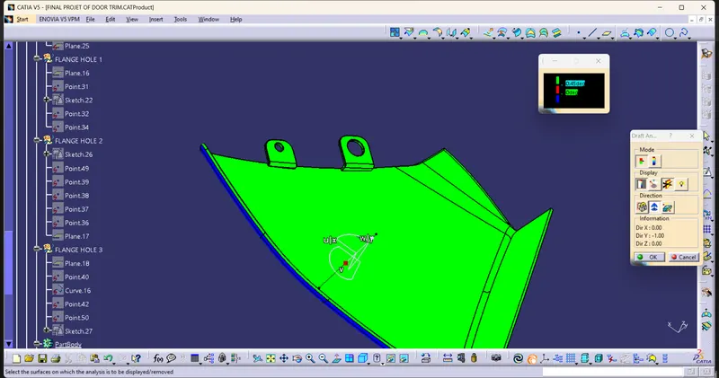
Draft analysis with the 2.9 degree .
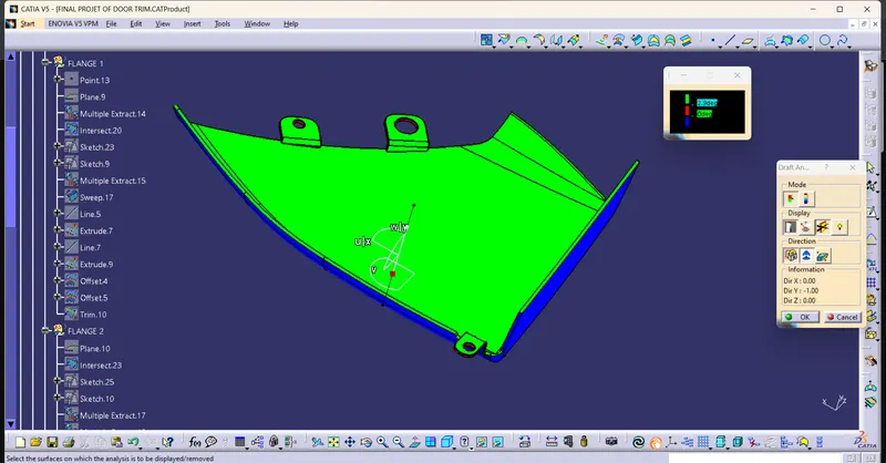
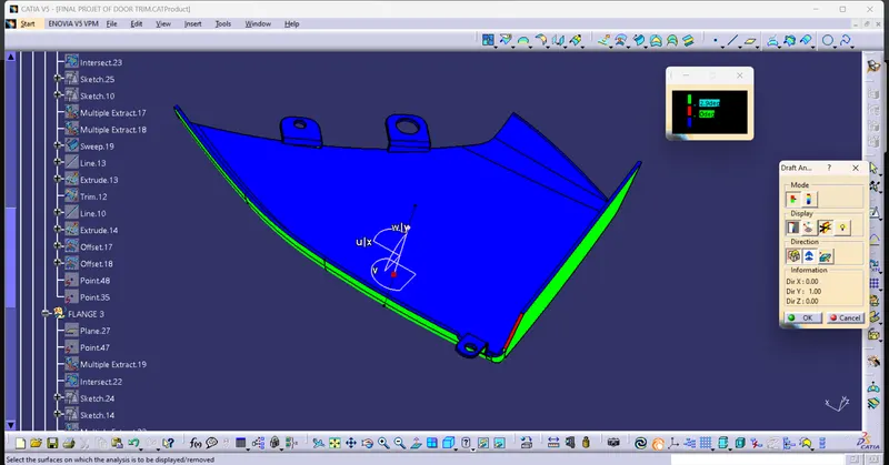
Draft analysis for flanges with 0.45degre:
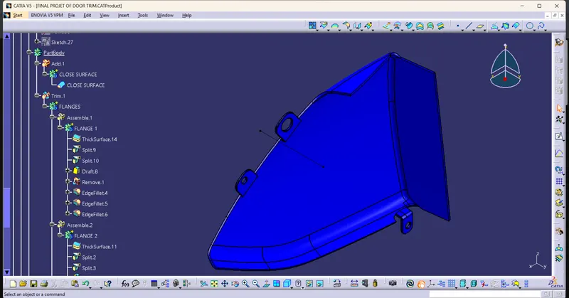
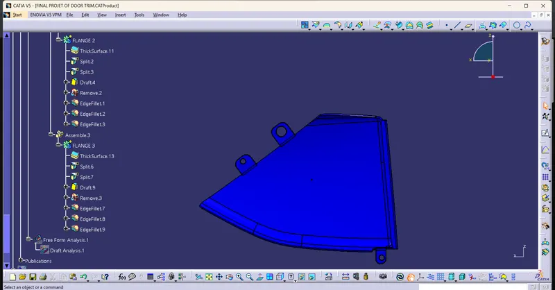
Publications:
Bottle holder:
Class-A:
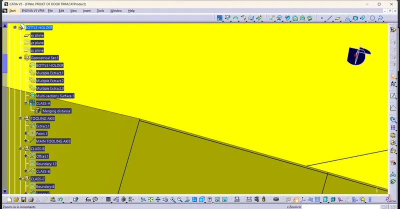
firstly prechecked the class-A with boundary so foiund a error in the surface irregular length was appeared on the below diagram so have to extract the surface in complimentary mode than form a surface through multisection command
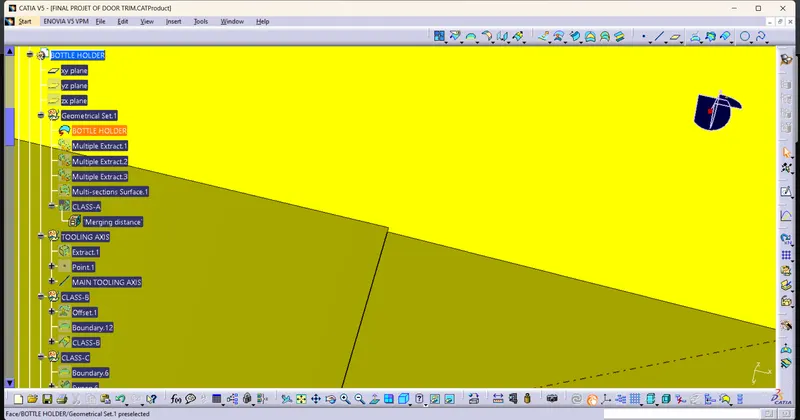
Updated class-A:
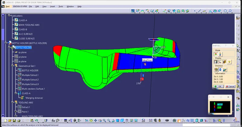
Draft analysis for class -A:
Note:
To Class-A engineer of the bottle holder .
we are from the design department
Here we identify a error on the draft analysis it was high light with measure pointer on the blue region in the below diagram it was shows as 0 Degrees.So please check once correct the position of tooling axis and errors than itt was help to create a Class -B and Class-A surfaces to complete to clsoed surface.
thank you.
Class-B:
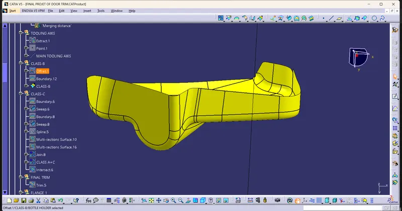
offset the Class-A surface than itwas offseted without any errors
Class-C:
- Take A surface boundary as reference to construct the C surface.
- Class-A nd Class-B sides of the surface are parallel to tooling axis so we have take a sweep of reference surfaceof 90Degree thanonly intersect the C surface with B surface.
- Class-A nd Class-B sides of the surface are perpendicular to tooling axis so we have take a draft direction with 3Degree thanonly intersect the C surface with B surface.
- in the process some edges and curves are not form with good quality so we have to do a multisection surface at that surface we get quality surface at that position.
- Finally edges of the sweep are not connecte we can extrapolate the edges and trim them at last use join command to joinall the sweeps and multisection as one surface.
A+c : join Class-A with Class -C than trim with B-surface finally form a Final trim surface .
check with boundary command if their any gap in between onthat surface.If not than use part wok bench command of closed surface convert into surface into solid body
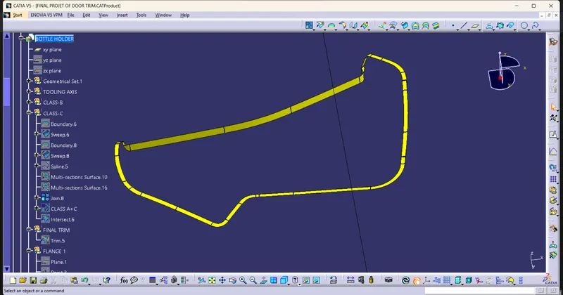
Draft analysis of Closed surface:
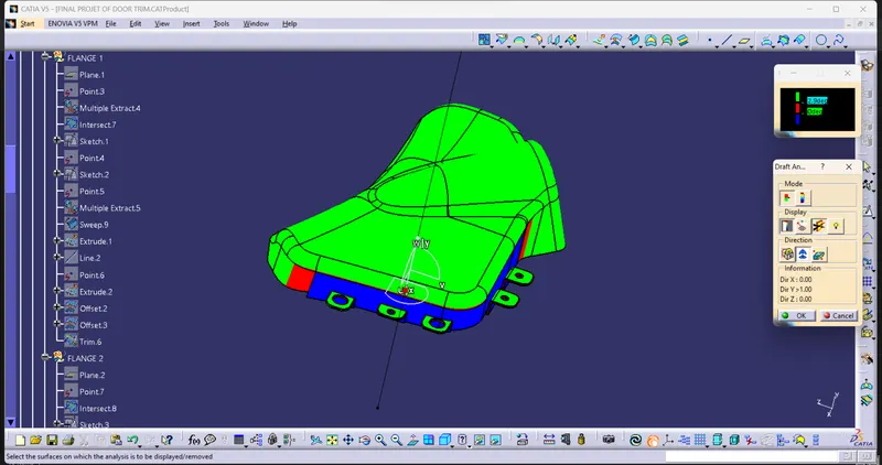
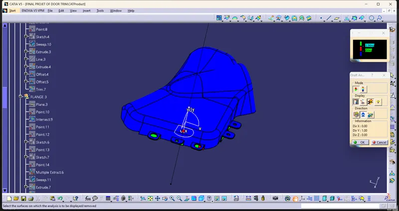
Draft analysis for flanges with 0.45degrees:
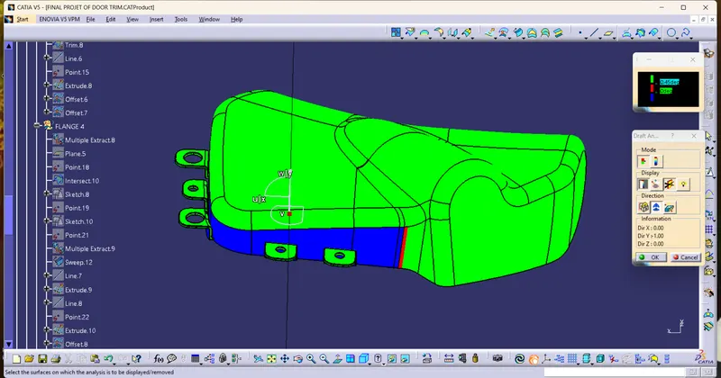
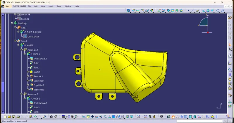
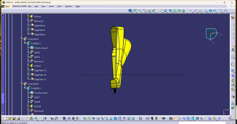
Heatstakes for hole:
- Take a heat stake point as referecne than create perpendicular plain to the tooling axis.
- Create a sketch refernce plain as top view than draw a circle with 8.5 mm it is 1mm more than heatstake so it is used to create a clearence between the flange and heat stake .
- so after create a skeatch and pad it with same height of the heat stake than give a draft angle with 0.5 degree and pulling direction is tooling axis but in downward direction means adding a surface to the that surface .
- on remove this surface from the flange hole was created.
- Here we are adding material beacuse inthe previous drafting to heat stake we are give a direction in topward means it is removing so here also give same as that we dont provide clearence .
- That is the reason behind this to dowmward direction was given.
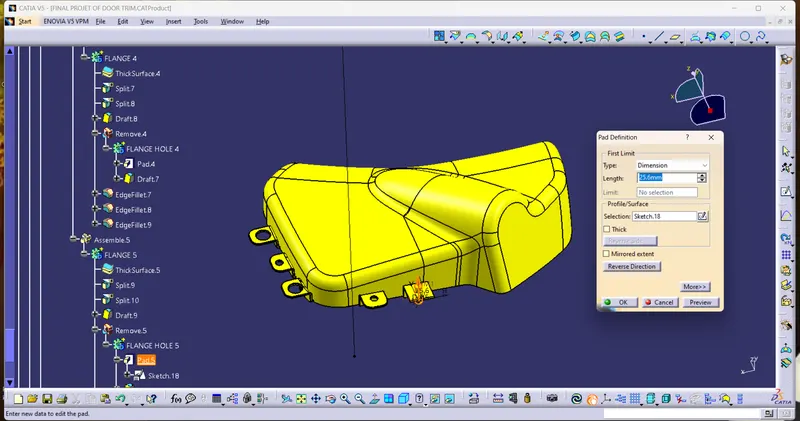
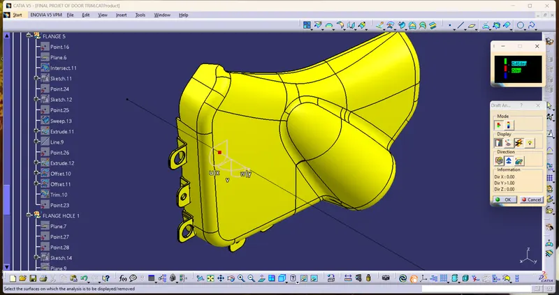
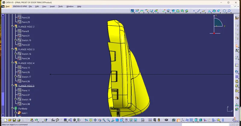
Locator hole and publications:
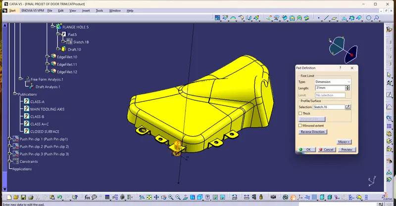
- Take a locator point as referecne than create perpendicular plain to the tooling axis.
- locator is 16mm in vertica and horizontal is 15mm so means around 7.5mm radius
- Create a sketch refernce plain as top view than draw a circle with 17 mm it is 1mm more than heatstake so it is used to create a clearence between the flange and heat stake .
- so after create a skeatch and pad it with same height of the locator than give a draft to them pulling direction is tooling axis but in downward direction means adding a surface to the that surface .
- on remove this surface from the flange hole was created.
Apply material fopr the parts:
ABS, polypropylene and SMA plastics shape lightweight, durable and complicated shapes for consoles. Consoles include armrests, cup holders, and storage spaces.
Arm rest:
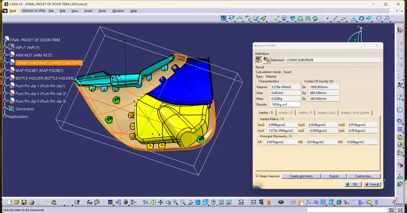
Lower substrate :
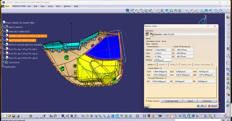
Map pocket:
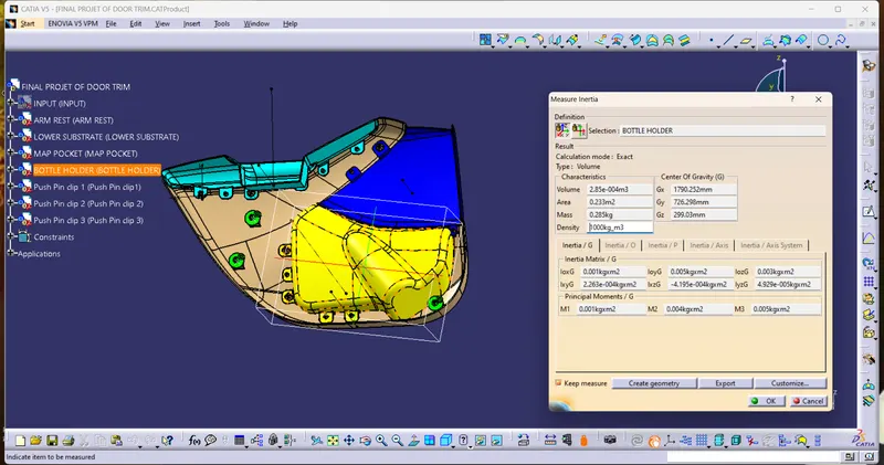
Bottle holder:
Material:ABS, polypropylene and SMA plastics shape lightweight, durable and complicated shapes for consoles. Consoles include armrests, cup holders, and storage spaces.
plastic
Acrylonitrile butadiene styrene (ABS) (chemical formula (C8H8)x·(C4H6)y·(C3H3N)z ) is a common thermiplastic polymer. Its glass transistion temperature is approximately 105 °C (221 °F).ABS is amorphousand therefore has no true melting point.
ABS is a terpolymer made by polymerizing styrene and acrylonitrile in the presence of polybutadiene. The proportions can vary from 15% to 35% acrylonitrile, 5% to 30% butadiene and 40% to 60% styrene. The result is a long chain of polybutadiene crisscrossed with shorter chains of poly(styrene-co-acrylonitrile). The nitrile groups from neighboring chains, being polar, attract each other and bind the chains together, making ABS stronger than pure polystyrene. The acrylonitrile also contributes chemical resistance, fatigue resistance, hardness, and rigidity, while increasing the heat deflection temperature. The styrene gives the plastic a shiny, impervious surface, as well as hardness, rigidity, and improved processing ease. The polybutadiene, a rubbery substance, provides toughness and ductility at low temperatures, at the cost of heat resistance and rigidity. For the majority of applications, ABS can be used between −20 and 80 °C (−4 and 176 °F), as its mechanical properties vary with temperature. The properties are created by rubber toughening, where fine particles of elastomer are distributed throughout the rigid matrix.
mechanical properties:
property value
youngs modulus (Gpa) ----------------------2.28
tensile strength(Mpa)-------------------------43
Flexural modulus (Gpa)----------------------2.48
Flexural strength (Mpa)-----------------------77
Notched Izod()Kj/m---------------------------0.203
Heat deflection Temperature,1.81Mpa,(C) --81
Acrylonitrile Butadiene styrene have high rigidity , impact,weldability,abrasion and strain resistance
it have high dimensional stability.
so it is majorly used in the door panels
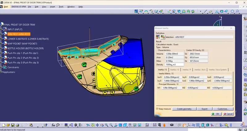
Arm rest:0.156kg
Lower substrate :0.528kg
Map pocket:0.174kg
Bottle holder:0.285kg
Total weight of the door trim =1.143kg
Push pin clip:
Here pushpin was asseble to dog house top face through assembly ocnstraints
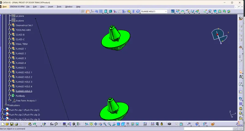
Assembly consraints:
- constraints are used in this fix and coincidence command to connect the pushjpin and dog house .
- Firstly fix the lower substrate as fix body use manipulation command to move the pushpin near to the dog house.
- coincide the axes of pusphin and dog house than click ok tan update it.
- At now select the coincidence command than select the faces of the pushpin and dog house top face than click ok upddate it .It was connected
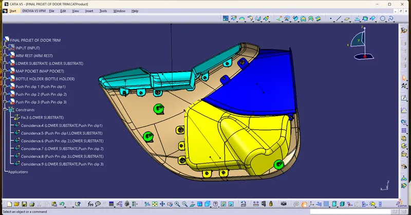
Final Assembly:
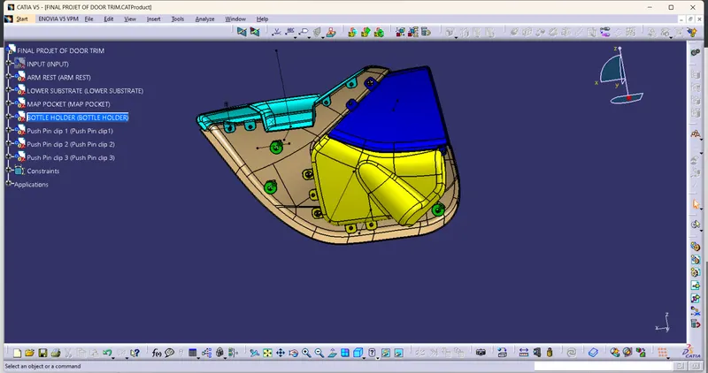
Conclusion:
For given all class -A surfaces are created tooling axis Class-B, Class-C surface than all are converted into closed surfaces.
B side attachnment features are also created. report was created what i was observed in the creation of assembly which errors are i was find it mentioned in the report.
******THANK YOU*********