Week 12- Final project
FINAL PROJECT– DOOR TRIM
- To create a DOOR TRIM from the inputs of class A surface along with master section by following the design rules followed in tier 1 and OEM industries using catia v5.
STEPS TO BE FOLLOWED :
- To create individual tooling axis for the parts and perform draft analysis on the class A surface.
- To create the class B and class C surfaces from the given class A surface.
- To form a solid geometry by combining all the surfaces.
- To decide an attachment strategy for the part and create engineering features in reference from the master section provided.
- To perform draft analysis on the solid part model with all engineering features.
- To assemble all the components togehter to obtain the final trim.
INTRODUCTION-
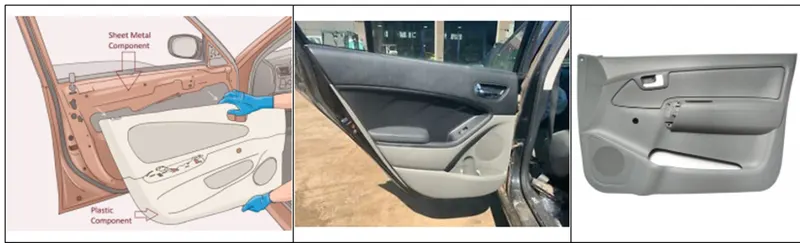
The door panel is the interference between the interior of the car and the inner workings of the door. Generally, the door panel is divided into two parts of easy designing like arm rest, map pocket, lower substrate, bottle holder, these requires one of the toughest requirements among the interior parts of the car. This should be designed to with stand the load while being less than 2mm in the thickness and also protect the occupants during collisions. Door currently has an inner full width panel consisting of electronic windows. Central locking system and speakers. These panels typically consist of a covered with either textiles or plastics.
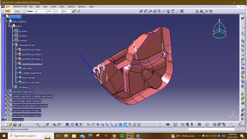
Input of Class A surface and Master section:
- BACK SIDE:
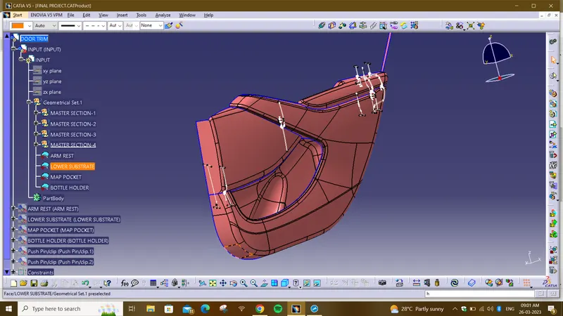
- FRONT SIDE:
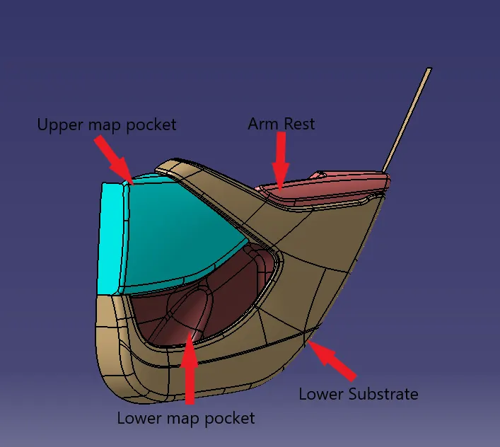
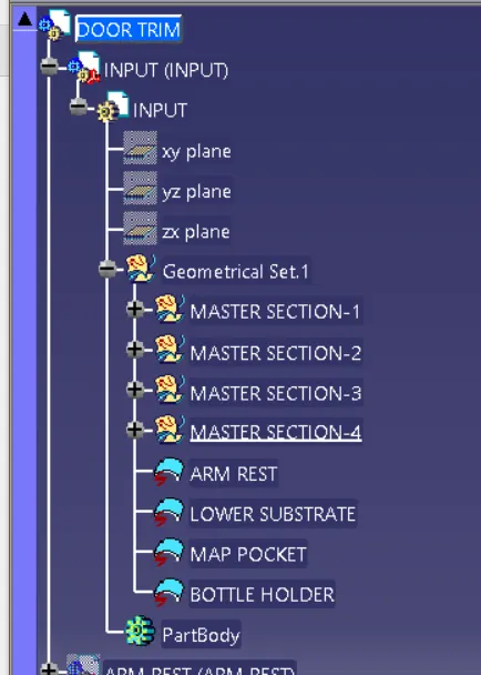
- First segregate the master sections and then copy the surfaces from product file to individual part files.
- Now work on the bodies individually to make them as closed surfaces and then into solid bodies.
1. DOOR ARM REST
An arm rest offers the possibility of comfortably positioning your hand when driving on a motorway or standing in traffic, yet not only. Depending on the equipment of an individual vehicle, it can also combine the functions of the control console of the vehicle’s electrical systems and the practical storage compartment. Car armrests are manufactured from a variety of materials, including a hard plastic base, a soft foam top, and an outer pad. All these components should provide comfort of use, durability, stability and safety.
Class-A Surface :-
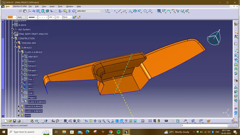
In automotive design, a class A surface is any of a set of free form surfaces of high efficiency and quality. It gives the aesthetic of the component which is created by the styling team and gives to the part design engineer to create the part with all engineering aspects.
Taken class A surface for Arm Rest from given Class A surface.When checked continuity of the class A surface it’s not smooth one corner. So making smooth I have done some modification on that corner. Finally, we have got class A surface.
TOOLING AXIS:
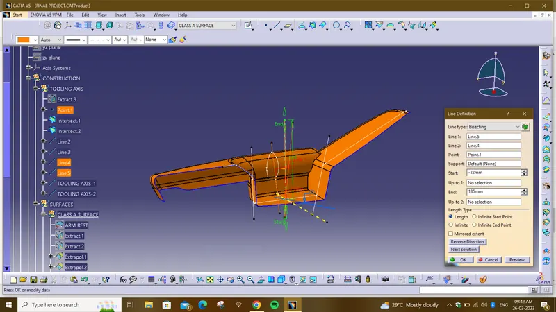
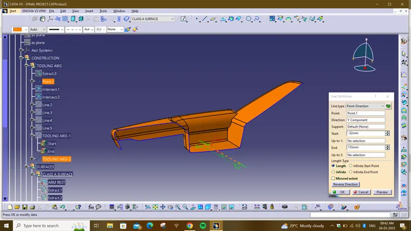
Tooling axis represents the opening and closing of the mold core and cavity during the manufacturing of the components. A plastic product designer should consider the best tooling direction to cutdown the cost of the component very less.
Method opted for creating tooling axis for the ARM REST
- Step 1: Insert a geometrical set . Extract the base surface and create a point at its center using point on surface option from point tool. Look for suitable axis to create a tooling axis so that all faces clear tooling .
- Step 2: Create an axis system without current option ticked at the above point. Create a position sketch with zy plane from axis system and above point as reference point.
- Step 3: Use intersect 3d objects option from project tool to create 2 lines by selecting a suitable plane(zy). Now create 2 lines which coincide with lines on both sides of the projection point . Create a line using bisect option .Allign the line in required axis direction.This is our Y tooling axis .
- Step 4: To create tooling axis about x direction, create a position sketch with xz plane as reference plane and projection point as the first point we created . Use cut section tool and create an intersection using projection tool . Now create a line that coincides with this line .
- Step 5 : Draw a line from origin in horizontal direction and create and angle constraint of 5 degrees. Use bisect option to create a line between that above lines . This is out X tooling axis .
- Step 6 : Create a new line using bisect option between X tooling and Y tooling line . this is our required Tooling Axis , Name this as tooling axis and publish it .
• Draft analysis of Class-A surface on Tooling axis direction:
-
DRAFT ANALYSIS OF CLASS A SURFACE:
The Draft Analysis command enables you to detect if the part you drafted will be easily removed. This type of analysis is performed based on color ranges identifying zones on the analyzed element where the deviation from the draft direction at any point, corresponds to specified values.
- Before going to drat analysis go to customized view parameter >under mesh >check material and then click ok.
- Now for draft analyses go to insert » analysis » feature draft analysis.
- Use the compasss to define the draft direction.
- In the colour scale change the draft angle to 2.95 degree.
- The component changes to green in indication of passing draft angle.
- Use running point to check the angle on the component.
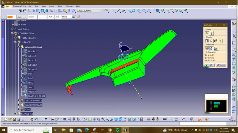
- SO the given class A surface cannot be cleared by the single tooling axis.
- so we take another tooling axis so as to clear the area which is not cleared by the main tooling axis.
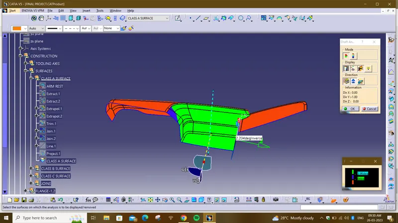
Class B surface :
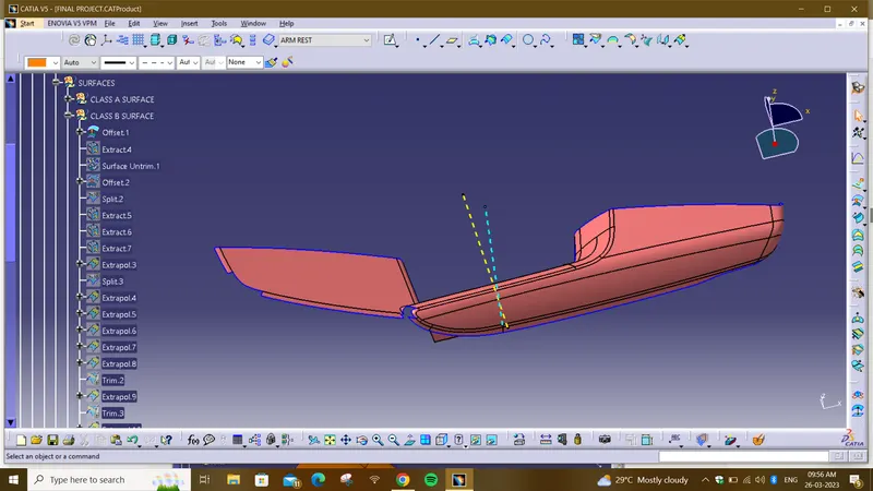
we offset the Class A surface and get the B surface body here we offset the 2.5mm value so we get the thickness is 2.5mm is mention in above so we offset the A surface for 2.5mm .
After the offset we get the surface but in that offset some patches of surface is missing so we required to solve it.
Initial CLASS B SURFACE:
Final Class B surface:
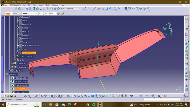
Class C surface
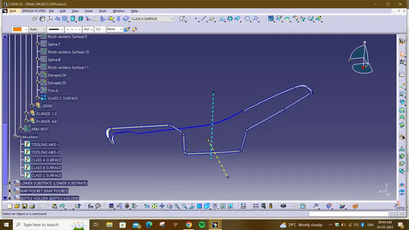
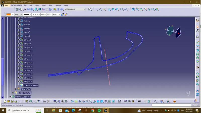
Using the multiple extract commands boundaries of class, A surface were extracted. Class C surface joins class A and Class B surfaces. It is created using the sweep command. Inputs for the sweep were extracted boundary, class a surface angle values and length of the sweep. Due to surface irregularities, it was not possible to make a single sweep. Hence several sweep and multi section were created, and finally they joined together to create a Class C surface.
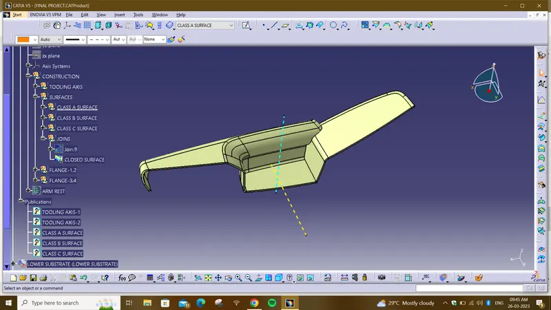
CLOSED SURFACE OR A+B+C SURFACE:
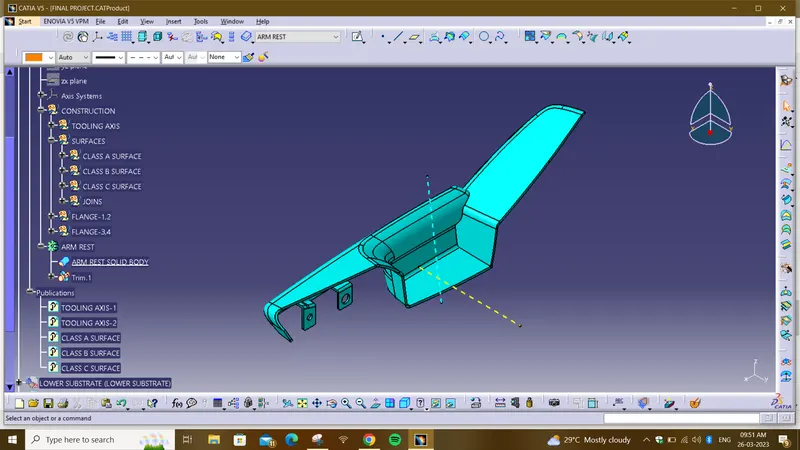
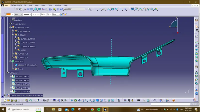
FINAL BODY VIEWS:
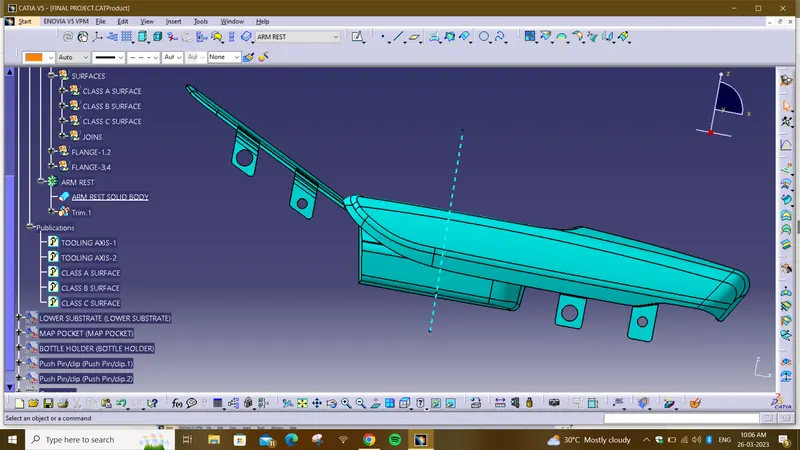
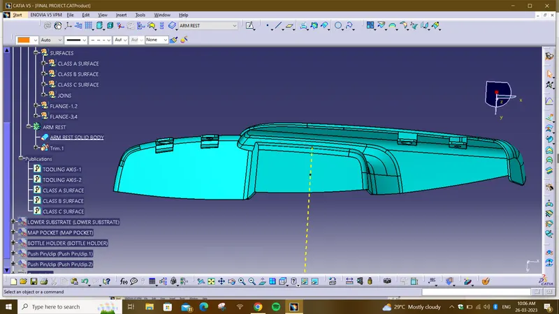
FINAL BODY DRAFT VIEWS WITH MAIN TOOLING AXIS:
- Draft analysis is cheked with 2.95 deg.
ISOMETRIC DRAFT VIEW
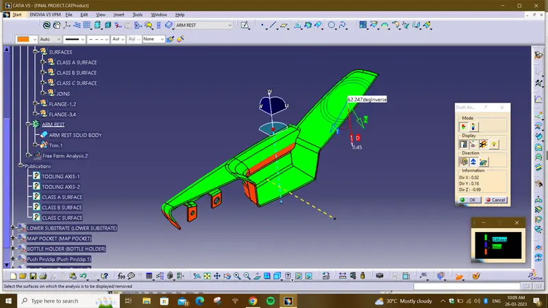
FRONT DRAFT VIEW
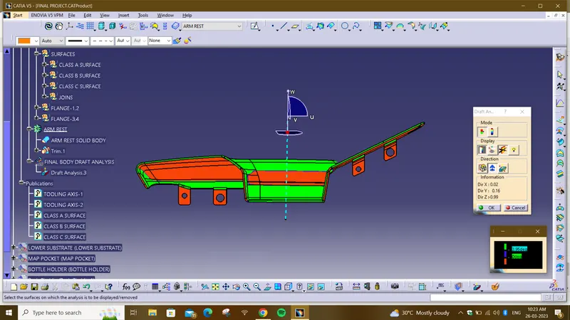
BACK DRAFT VIEW
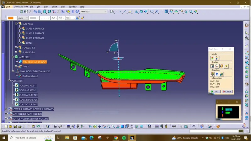
TOP DRAFT VIEW
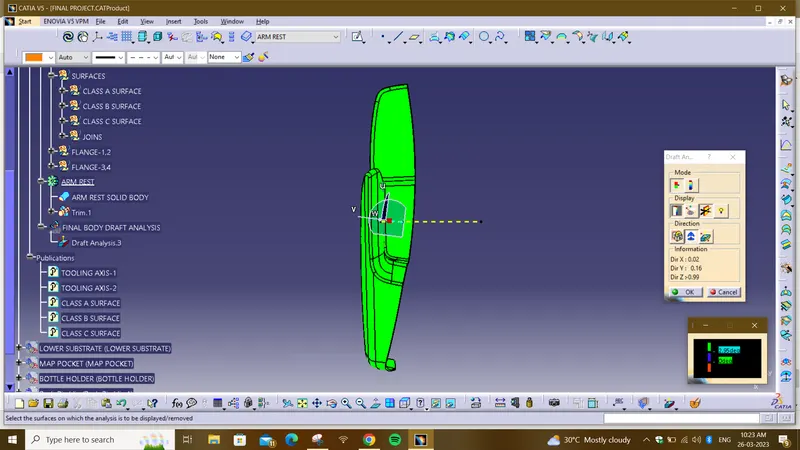
BOTTOM DRAFT VIEW
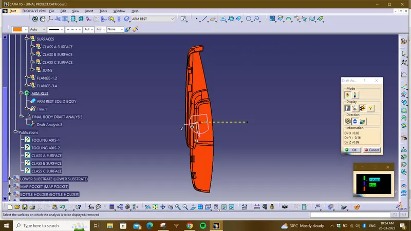
FINAL BODY DRAFT VIEWS WITH SIDE TOOLING AXIS:
- Draft analysis is cheked with 0.45 deg.
ISOMETRIC DRAFT VIEW
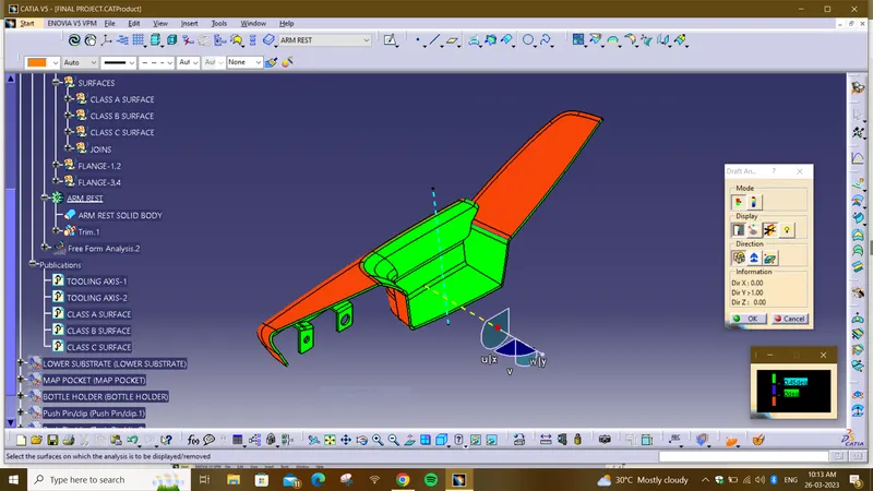
FRONT DRAFT VIEW
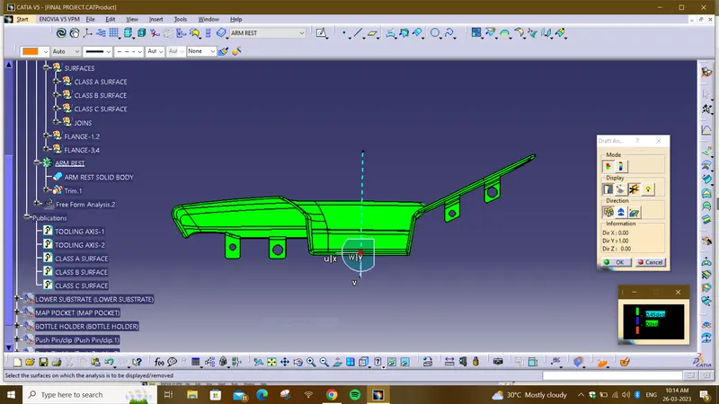
BACK DRAFT VIEW
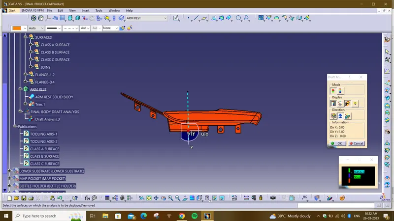
TOP DRAFT VIEW
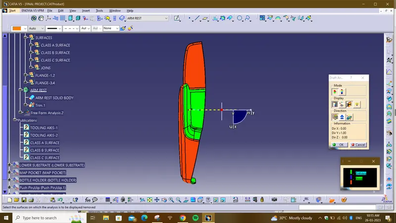
BOTTOM DRAFT VIEW
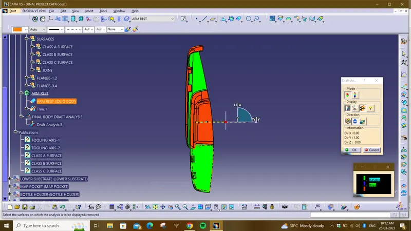
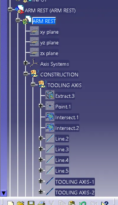
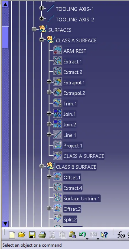
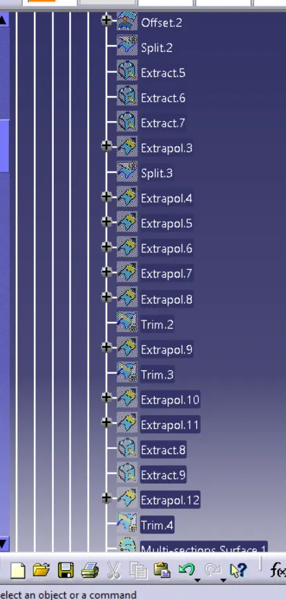
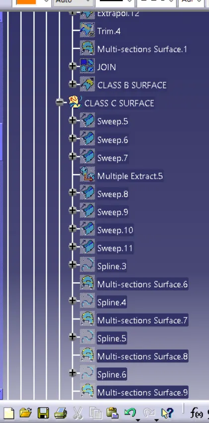
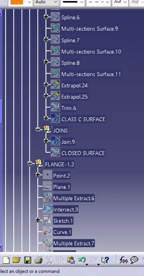
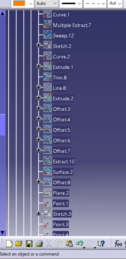
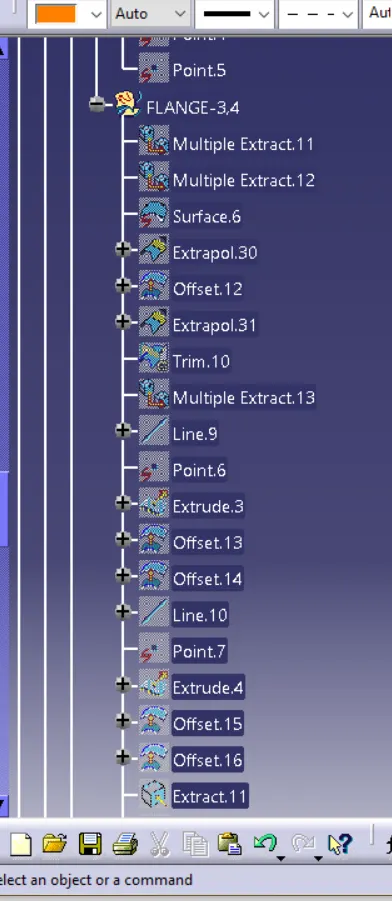
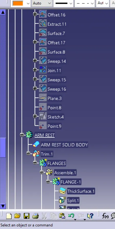
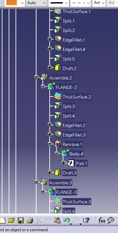
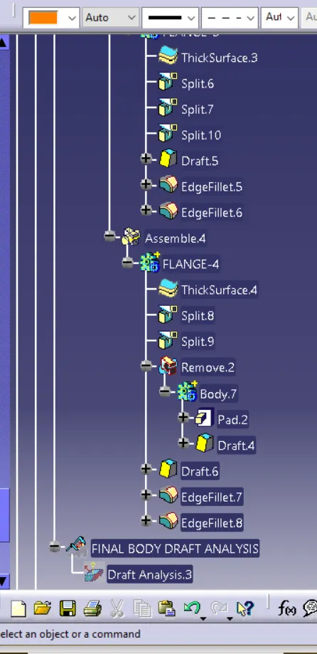
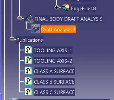
TREE STRUCTURE:
2. LOWER SUBSTRATE
Lower Substrate is the encapsulating aesthetic Part used in the door panel. It may house various features such as Wirings, Speakers and other sheet metal components behind it.
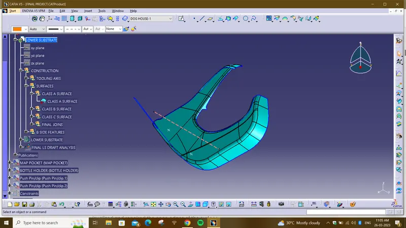
Class-A Surface :-
In automotive design, a class A surface is any of a set of free form surfaces of high efficiency and quality. It gives the aesthetic of the component which is created by the styling team and gives to the part design engineer to create the part with all engineering aspects.
TOOLING AXIS:
Tooling axis represents the opening and closing of the mold core and cavity during the manufacturing of the components. A plastic product designer should consider the best tooling direction to cutdown the cost of the component very less.
Extract the inner surface and check the continuity of the surface using join command or boundary command.
Create a point on surface 0mm.The line has been created using line command. The point direction option is used to create the main tooling axis in the Y direction.
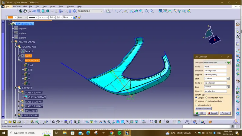
DRAFT ANALYSIS OF CLASS A SURFACE:
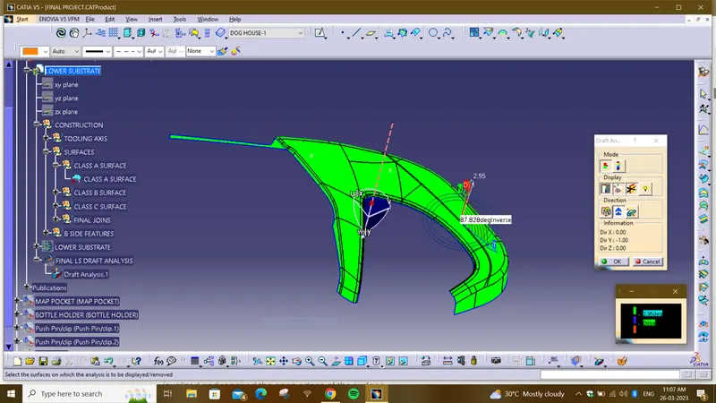
The Draft Analysis command enables you to detect if the part you drafted will be easily removed. This type of analysis is performed based on color ranges identifying zones on the analyzed element where the deviation from the draft direction at any point, corresponds to specified values.
- Before going to drat analysis go to customized view parameter >under mesh >check material and then click ok.
- Now for draft analyses go to insert » analysis » feature draft analysis.
- Use the compasss to define the draft direction.
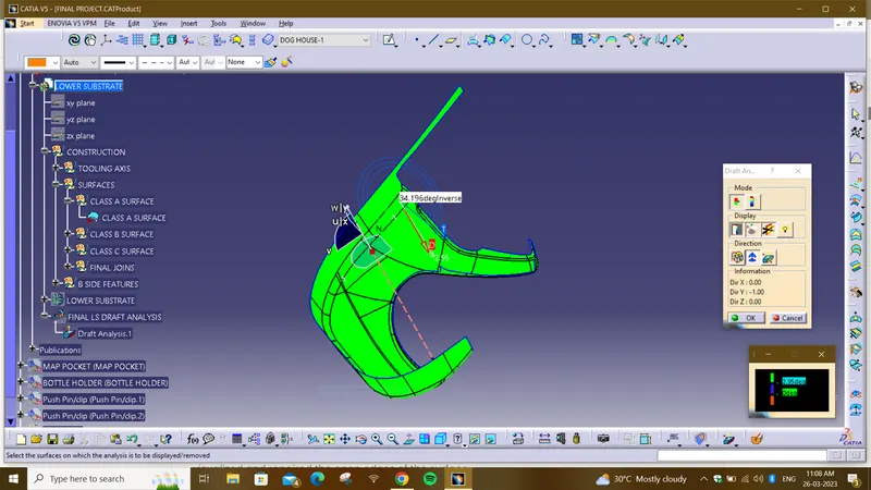
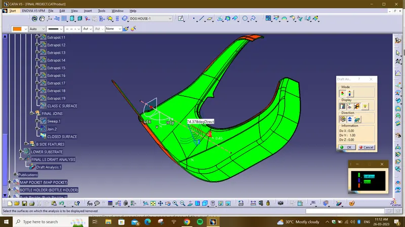
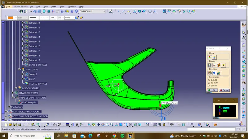
- In the colour scale change the draft angle to 3 degree.
- The component changes to green in indication of passing draft angle.
- Use running point to check the angle on the component.
Class B surface :
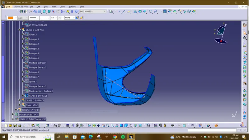
we offset the Class A surface and get the B surface body here we offset the 2.5mm value so we get the thickness is 2.5mm is mention in above so we offset the A surface for 2.5mm .
Class C surface
Using the multiple extract commands boundaries of class, A surface were extracted. Class C surface joins class A and Class B surfaces. It is created using the sweep command. Inputs for the sweep were extracted boundary, class a surface angle values and length of the sweep. Due to surface irregularities, it was not possible to make a single sweep. Hence several sweep and multi section were created, and finally they joined together to create a Class C surface.
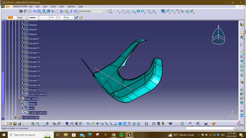
CLOSED SURFACE OR A+B+C SURFACE:
DRAFT ANALYSIS VIEWS OF CLOSED BODY:
ISOMETRIC VIEW
FRONT VIEW
HEAT STAKE:
Heat staking also known as thermoplastic staking is the process of joining two dissimilar materials together. In heat staking we use local heating and cooling to raise the temperature of plastic components and allow plastic reforming to be carried out. This reforming can be used in a wide variety of applications.
Thermal staking should be considered when the parts to be assembled are still in the design stage. Several configurations for boss/cavity design are available, each with specific features and advantages. Their selection is determined by such factors as type of plastic, part geometry, assembly requirements, machining and molding capabilities, and cosmetic appearance. Heat staking can be performed using wide range of thermoplastic materials including polypropylene, ABS, polycarbonate and many others.
The integrity of a thermal staked assembly depends greatly upon the geometric relationship between the boss and the thermal tip. Proper design will produce optimum strength with minimum flash.
Heat Stake Sketch :
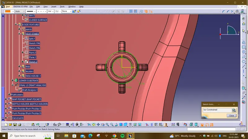
Take 5 & 7.5mm Dia Circles As Shown in figure below.
Here heat stakes created with draft 0.5 degree, fillet radius is 0.3mm and wall thickness is 2.5mm.
heat stakes designed by following the design rules.
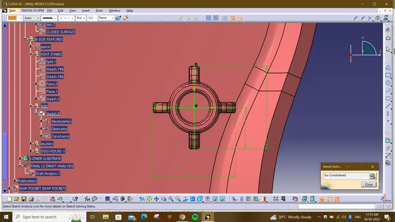
HEAT STAKE RIBS:
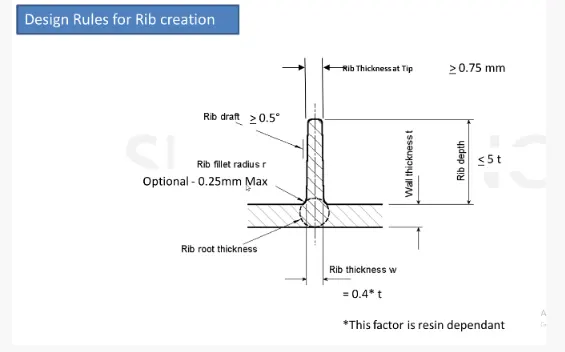
Next, the profile is extruded, to find the height,h=Wall thickness * 5
=2.5*5
= 12.5 mm
Therefore, the height is 12.5 mm. BUT IN MASTERSECTION it is 14.3mm so we consider 14.3 mm height.
The extruded surface is thickened,
Thickness,w=0.4*t
=0.4 2.5
=1mm
Therefore, the thickness of the rib is 1 mm.
LOCATORS
Typically, locating pins are used for controlled, fine tolerance positioning of a work piece.
A 2-way locating pin restricts motion along 1 axis (or 2 degrees of Freedom), like a round pin in a slot. Likewise, a 4-way pin restricts 4 degrees of freedom along 2 axes. A round locating pin located concentrically in a hole is a common application of a 4-way pin, and helps to further secure the piece.
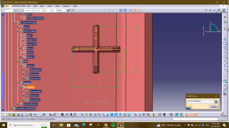
Here 4-way locator created with thickness 1mm ,draft 0.5 degree and the fillet value is 0.3 mm .
4 way Locator Sketch :
DOG HOUSE DESIGN:
- Dog house is an engineering feature used in the plastic trim design.
- Dog houses are used as supporting features. Sometimes other engineering features like snaps; locators, etc. are mounded on them to increase their strength.
- Dog houses are designed to avoid SINK MARK created on the CLASS-B surface by screw bosses and to solve the length issues when giving screw bosses which need to be assembled to other components.
Design rules for Dog house creation :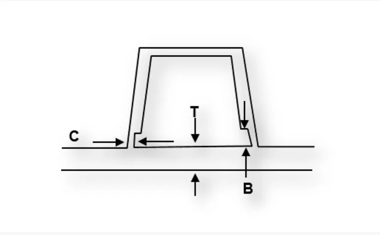
C" is where the doghouse contacts the backside of the surface.
Doghouse wall thickness at the intersection of the part wall ( C ) should be 40% or less than the main wall stock ( T ).
The height of ( B ) should be between 3.0 – 6.0 mm.
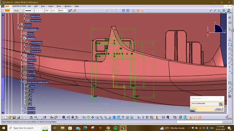
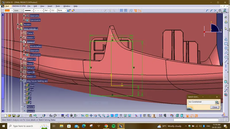
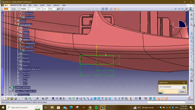
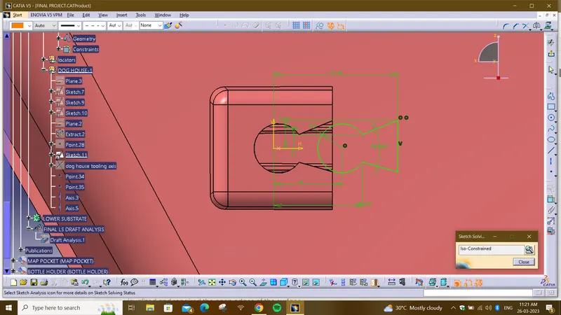
DOG HOUSE SKETCHES:
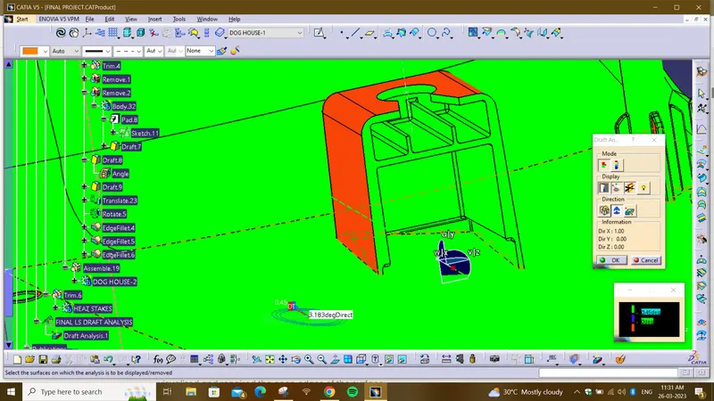
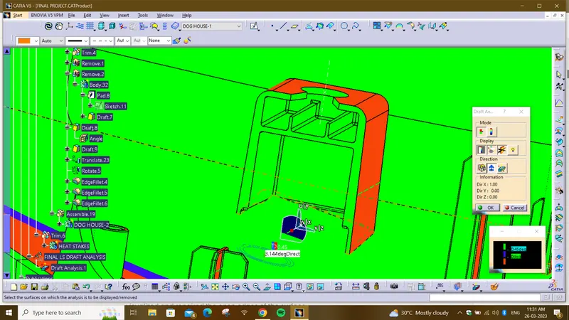
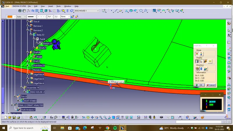
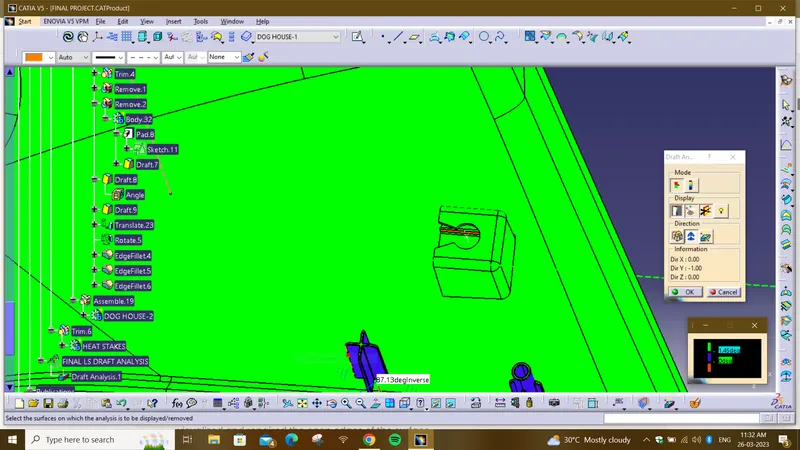
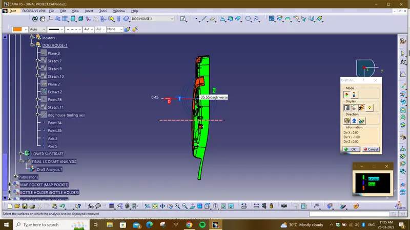
DRAFT ANALSIS OF DOG HOUSE:
FINAL BODY VIEWS:
ISOMETRIC VIEW
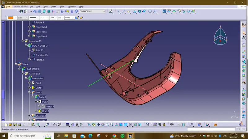
FINAL BODY DRAFT VIEWS:
ISOMETIC DRAFT VIEW
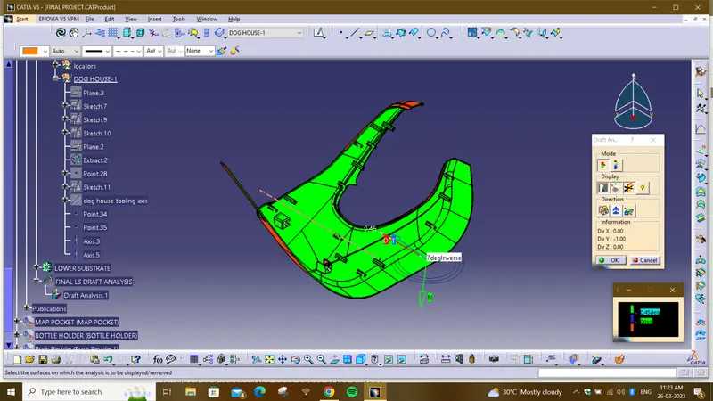
FRONT DRAFT VIEW
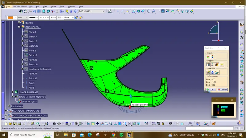
TOP VIEW
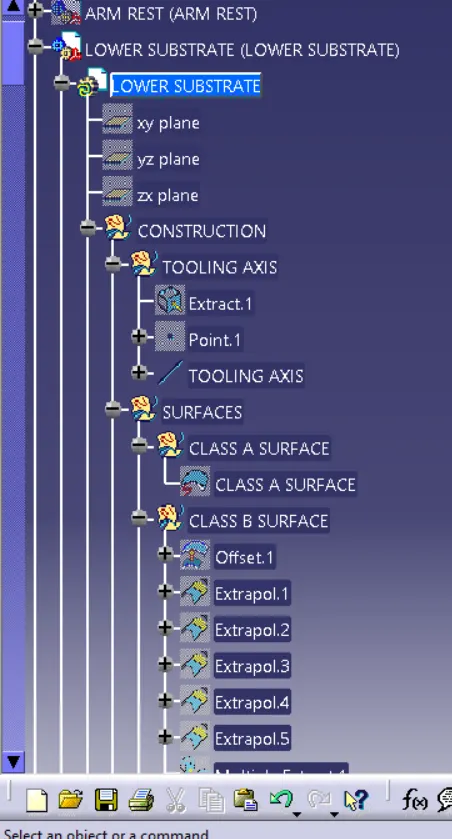
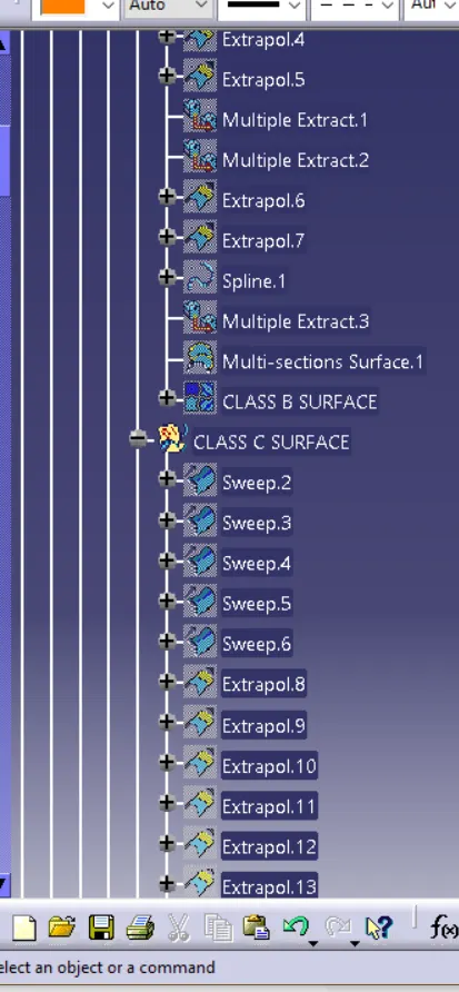
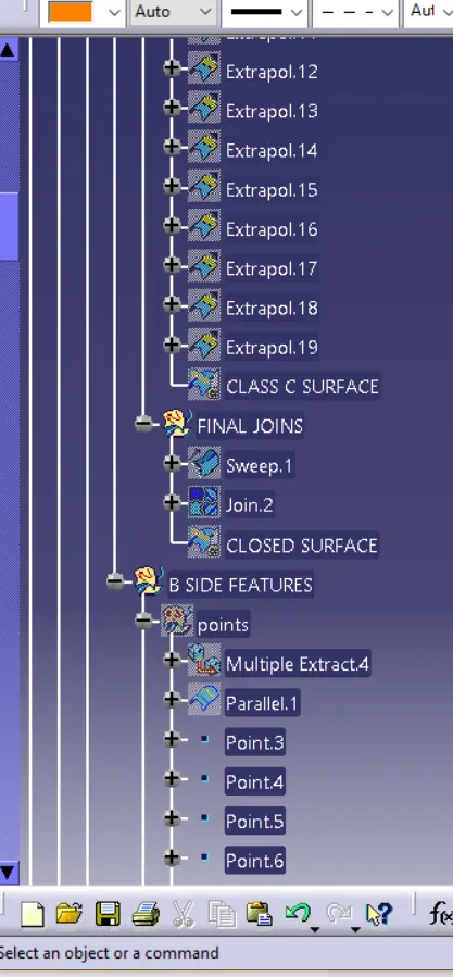
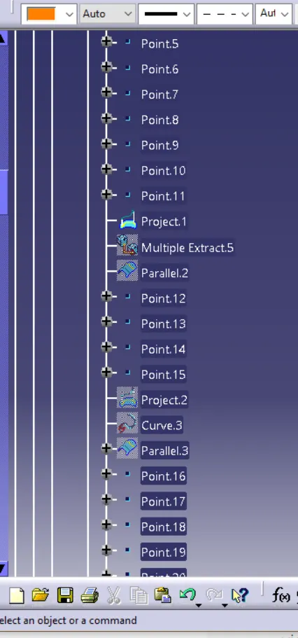
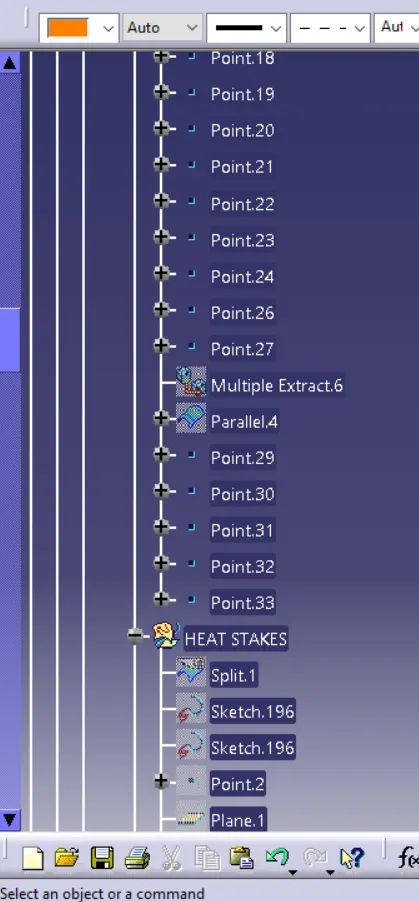
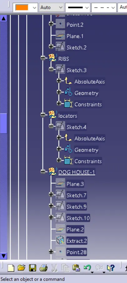
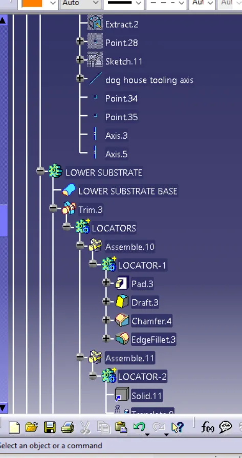
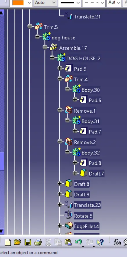
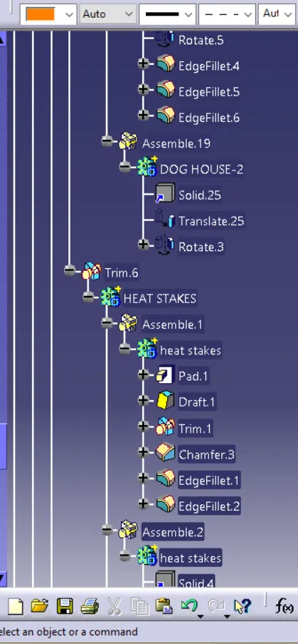
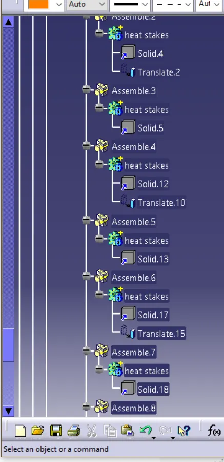
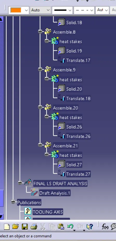
TREE STRUCTURE:

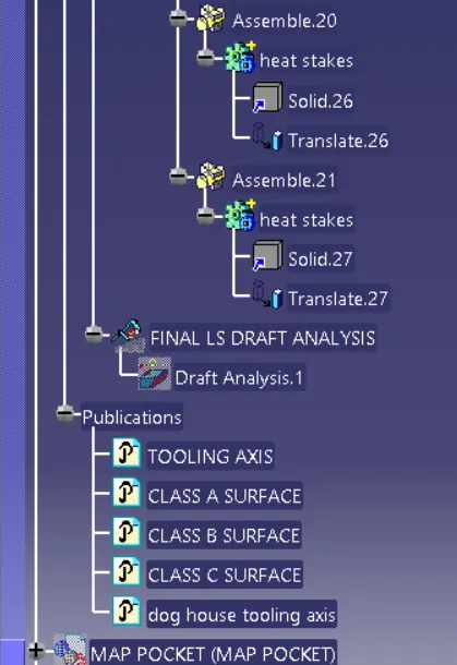
3. Map Pocket
- Map Pockets are genrally used as storage space on the door.
- In this case The Map Pocket is divided into 2 sections the upper and Lower
- The Upper Section acts as an enclosure from the inner parts and for aesthetics only.
Class-A Surface :-
In automotive design, a class A surface is any of a set of free form surfaces of high efficiency and quality. It gives the aesthetic of the component which is created by the styling team and gives to the part design engineer to create the part with all engineering aspects.
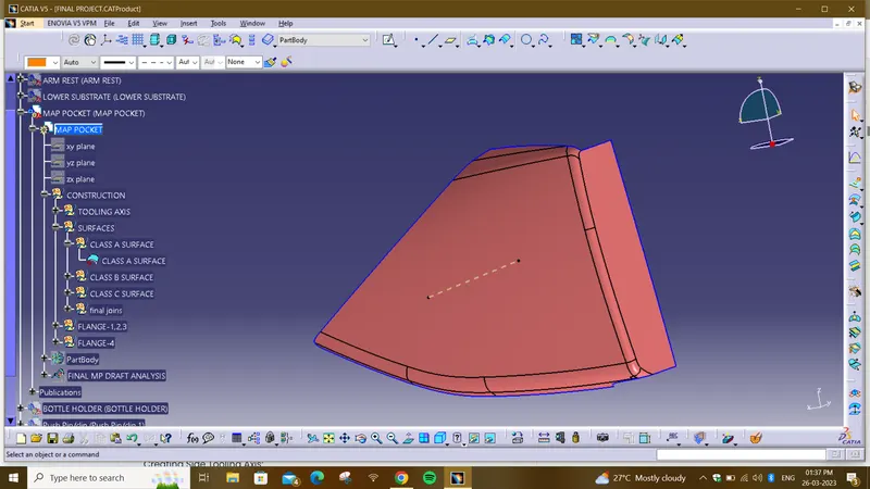
TOOLING AXIS:
Tooling axis represents the opening and closing of the mold core and cavity during the manufacturing of the components. A plastic product designer should consider the best tooling direction to cutdown the cost of the component very less.
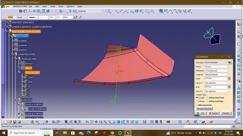
Extract the inner surface and check the continuity of the surface using join command or boundary command.
Create a point on surface 0mm.The line has been created using line command. The point direction option is used to create the main tooling axis in the Y direction.
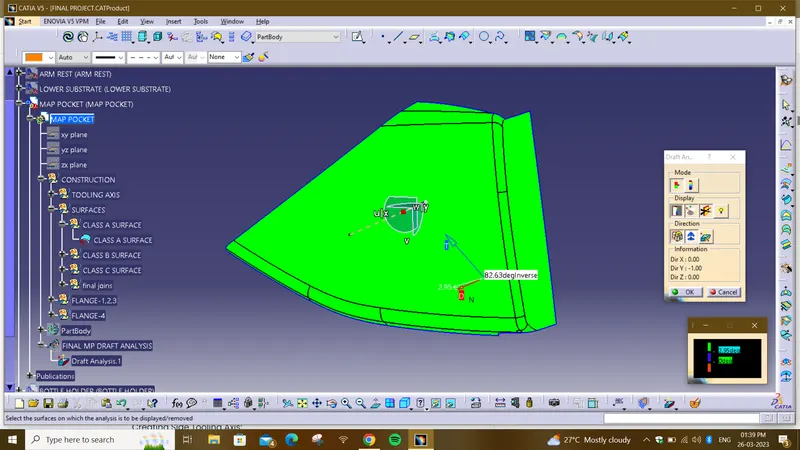
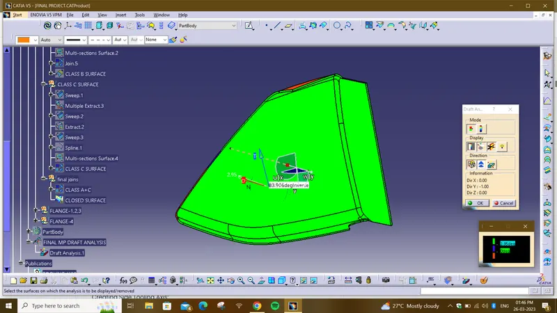
DRAFT ANALYSIS OF CLASS A SURFACE:
The Draft Analysis command enables you to detect if the part you drafted will be easily removed. This type of analysis is performed based on color ranges identifying zones on the analyzed element where the deviation from the draft direction at any point, corresponds to specified values.
- Before going to drat analysis go to customized view parameter >under mesh >check material and then click ok.
- Now for draft analyses go to insert » analysis » feature draft analysis.
- Use the compasss to define the draft direction.
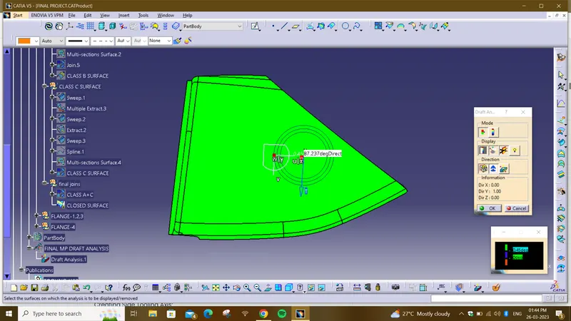
- In the colour scale change the draft angle to 3 degree.
- The component changes to green in indication of passing draft angle.
- Use running point to check the angle on the component.
Class B surface :
we offset the Class A surface and get the B surface body here we offset the 2.5mm value so we get the thickness is 2.5mm is mention in above so we offset the A surface for 2.5mm .
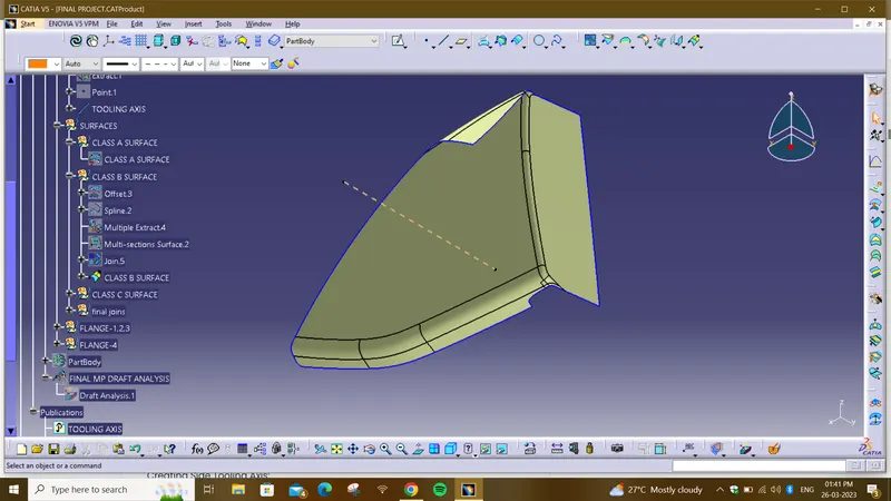
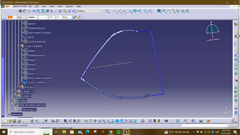
Class C surface
Using the multiple extract commands boundaries of class, A surface were extracted. Class C surface joins class A and Class B surfaces. It is created using the sweep command. Inputs for the sweep were extracted boundary, class a surface angle values and length of the sweep. Due to surface irregularities, it was not possible to make a single sweep. Hence several sweep and multi section were created, and finally they joined together to create a Class C surface.
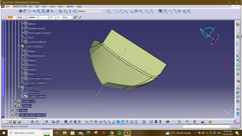
CLOSED SURFACE OR A+B+C SURFACE:
DRAFT ANALYSIS VIEWS OF CLOSED BODY:
ISOMETRIC VIEW
FRONT VIEW
FINAL BODY VIEWS:
ISOMETRIC VIEW
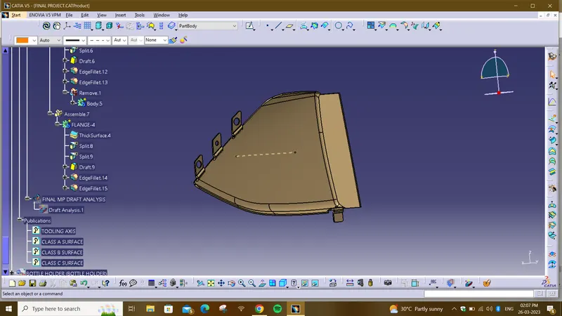
TOP VIEW
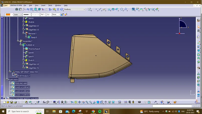
BOTTOM VIEW
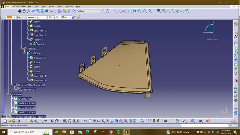
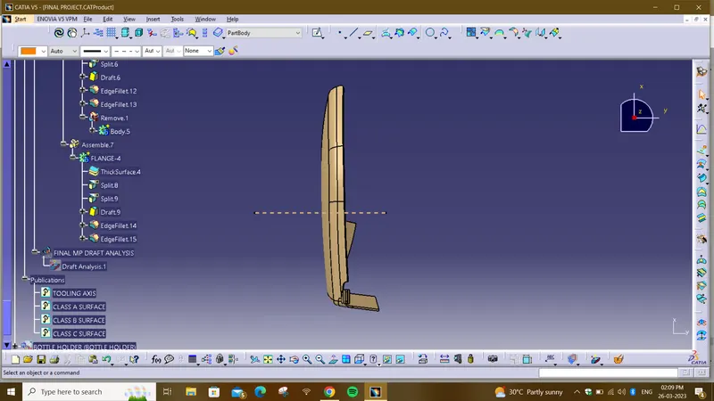
RIGHT SIDE VIEW
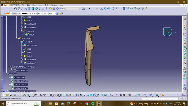
LEFT SIDE VIEW
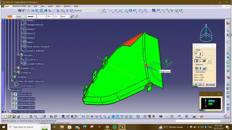
FINAL BODY DRAFT VIEWS:
ISOMETIC DRAFT VIEW
FRONT DRAFT VIEW
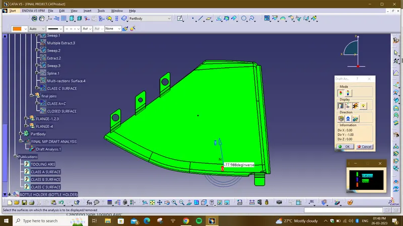
TOP VIEW
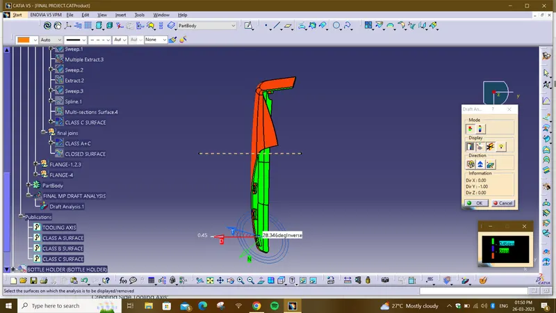
TREE STRUCTURE:
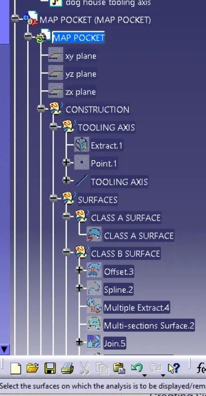
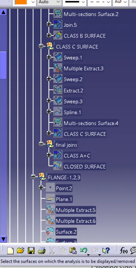
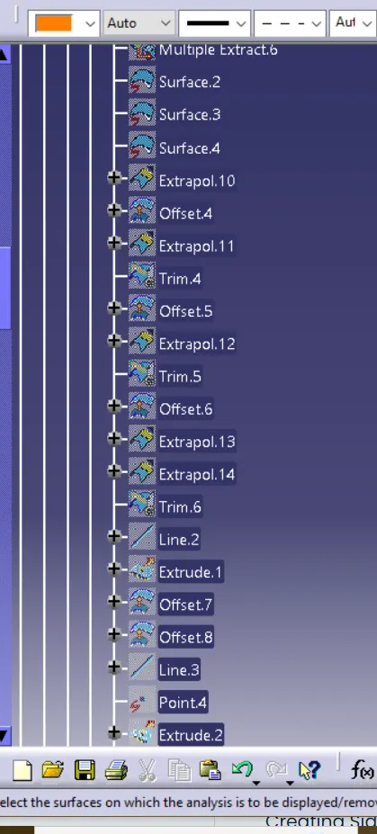
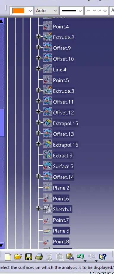
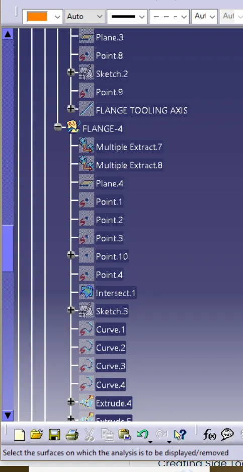
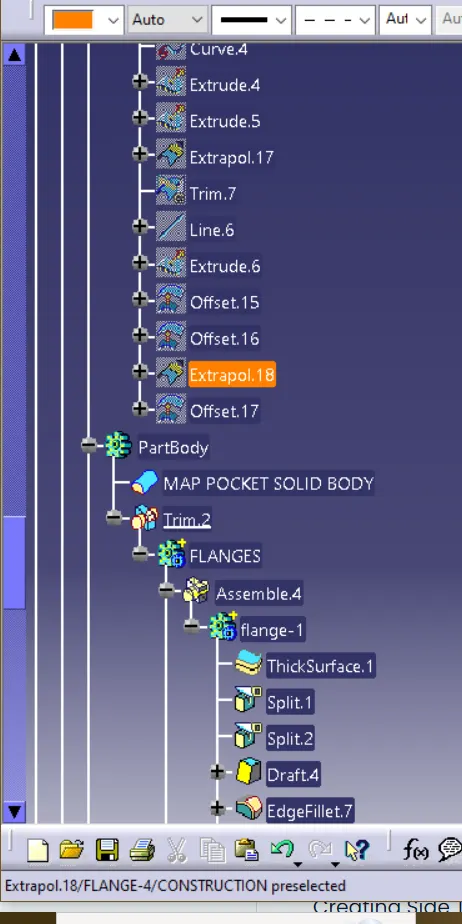
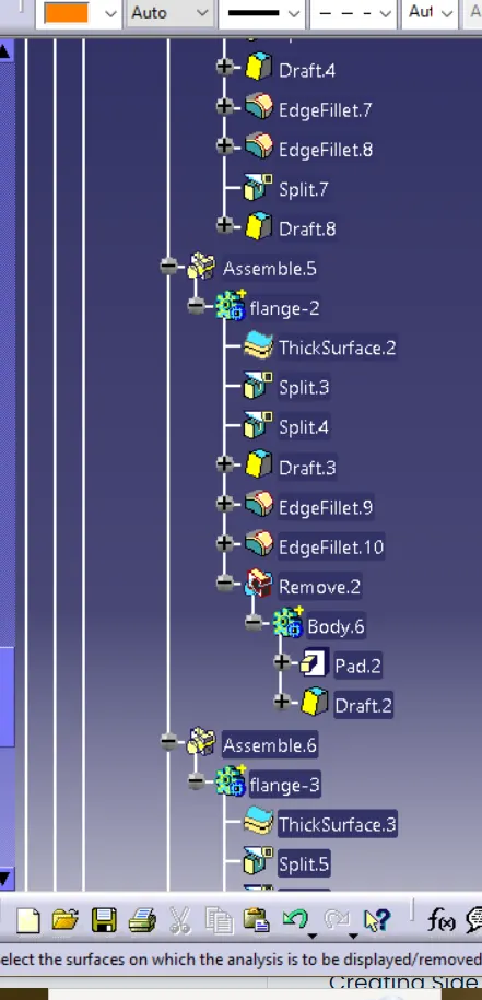
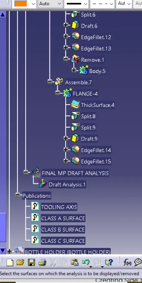
4. BOTTLE HOLDER
Class-A Surface :-
In automotive design, a class A surface is any of a set of free form surfaces of high efficiency and quality. It gives the aesthetic of the component which is created by the styling team and gives to the part design engineer to create the part with all engineering aspects.
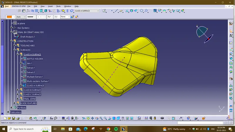
TOOLING AXIS:
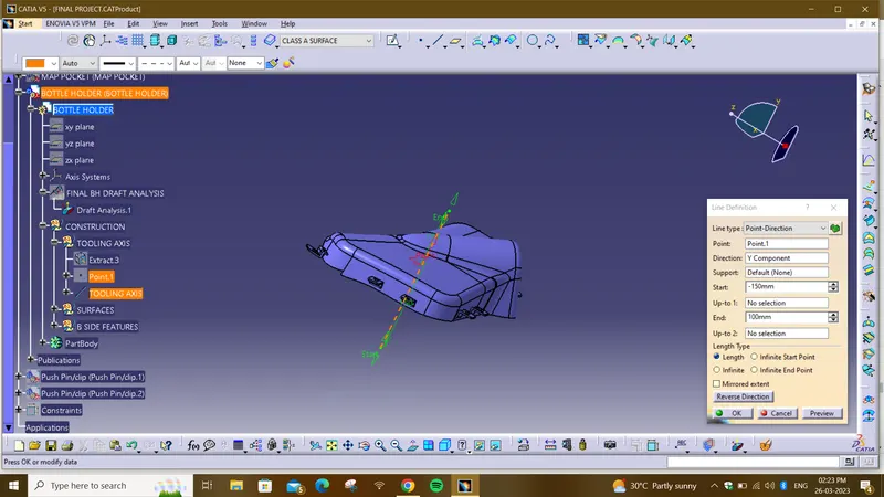
Tooling axis represents the opening and closing of the mold core and cavity during the manufacturing of the components. A plastic product designer should consider the best tooling direction to cutdown the cost of the component very less.
Extract the inner surface and check the continuity of the surface using join command or boundary command.
Create a point on surface 0mm.The line has been created using line command. The point direction option is used to create the main tooling axis in the Y direction.
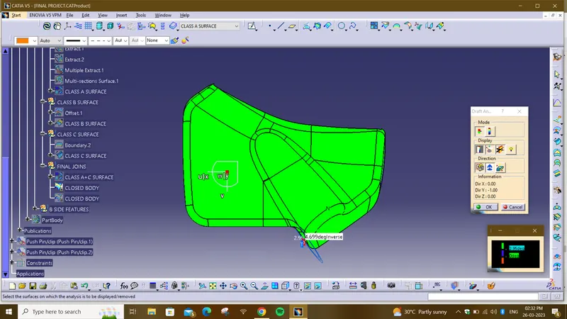
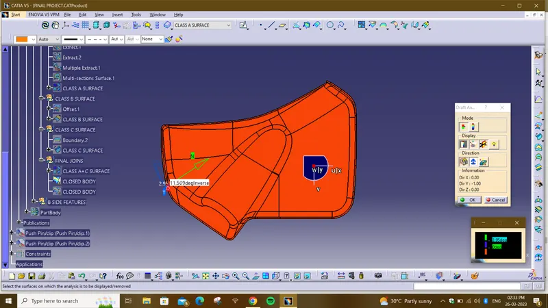
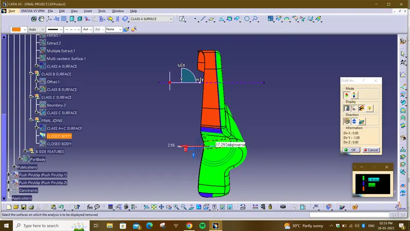
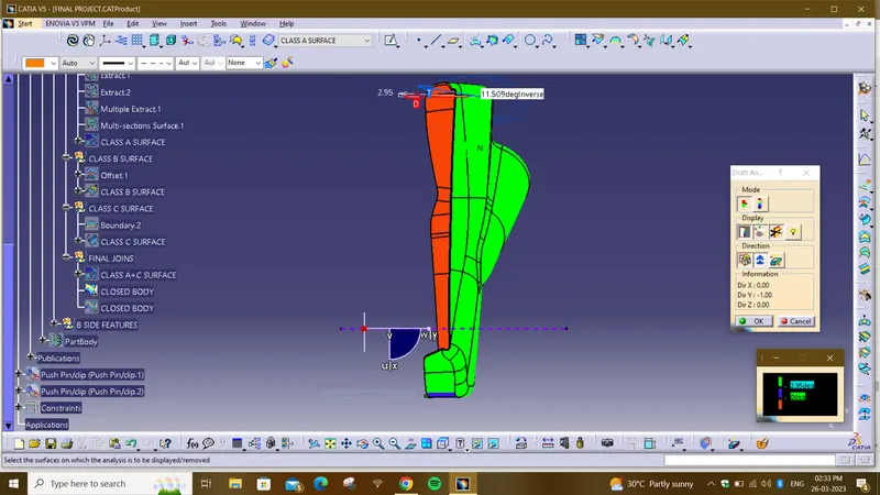
DRAFT ANALYSIS OF CLASS A SURFACE:
The Draft Analysis command enables you to detect if the part you drafted will be easily removed. This type of analysis is performed based on color ranges identifying zones on the analyzed element where the deviation from the draft direction at any point, corresponds to specified values.
- Before going to drat analysis go to customized view parameter >under mesh >check material and then click ok.
- Now for draft analyses go to insert » analysis » feature draft analysis.
- Use the compasss to define the draft direction.
- In the colour scale change the draft angle to 3 degree.
- The component changes to green in indication of passing draft angle.
- Use running point to check the angle on the component.
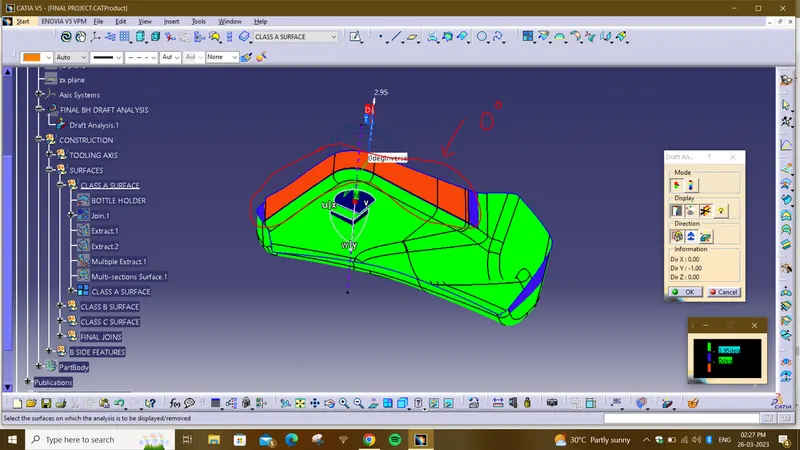
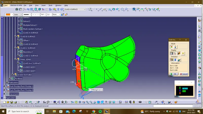
- The given class a surface is not provided with the draft so we have to request the styling surface engineer to give necessary draft.
- 0 deg draft or perpendicular flanges are given which are shown in red colour needs to be modified.
- Blue colour patches indicates that there is draft but it is less han 3 deg.
Class B surface :
we offset the Class A surface and get the B surface body here we offset the 2.5mm value so we get the thickness is 2.5mm is mention in above so we offset the A surface for 2.5mm .
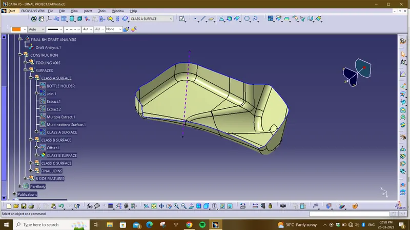
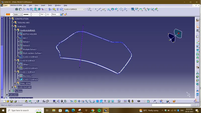
Class C surface
Using the multiple extract commands boundaries of class, A surface were extracted. Class C surface joins class A and Class B surfaces. It is created using the sweep command.
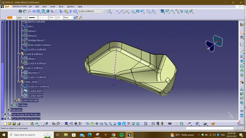
CLOSED SURFACE OR A+B+C SURFACE:
DRAFT ANALYSIS VIEWS OF CLOSED BODY:
ISOMETRIC VIEW
FRONT VIEW
BACK VIEW
LEFT VIEW
RIGHT VIEW
FINAL BODY VIEWS:
ISOMETRIC VIEW
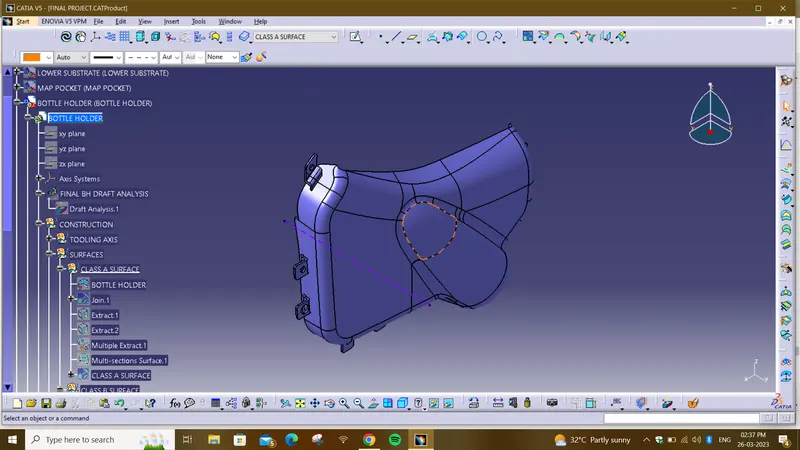
RIGHT SIDE VIEW
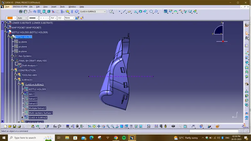
LEFT SIDE VIEW
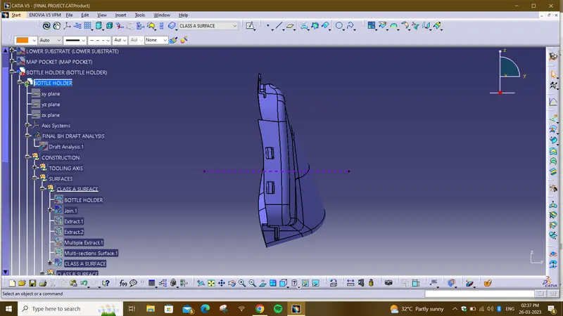
FRONT VIEW
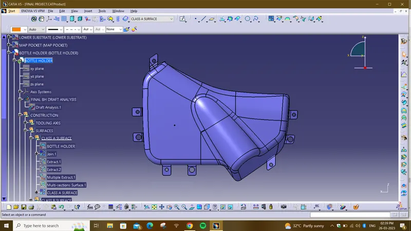
BACK VIEW
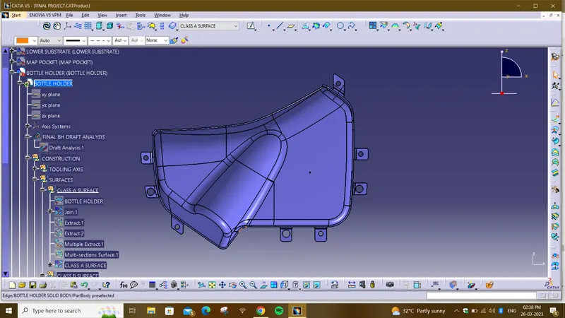
FINAL BODY DRAFT VIEWS:
ISOMETIC DRAFT VIEW
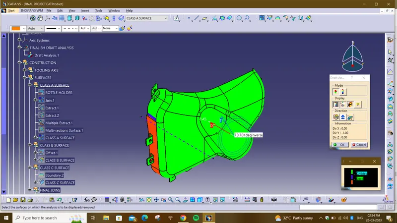
FRONT DRAFT VIEW
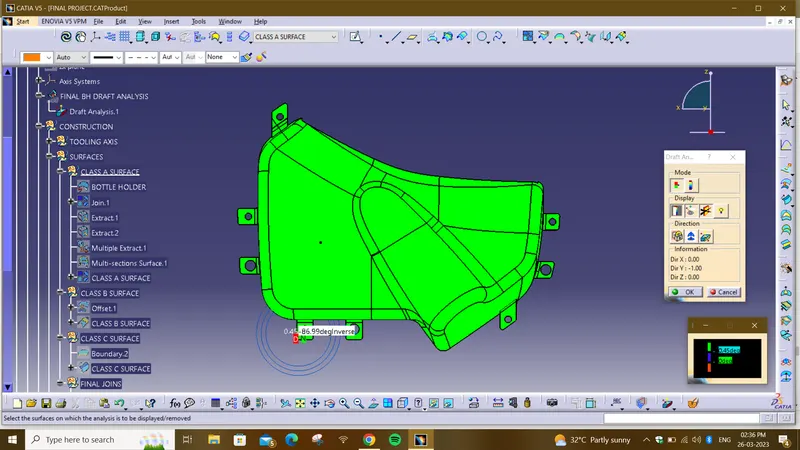
BACK VIEW
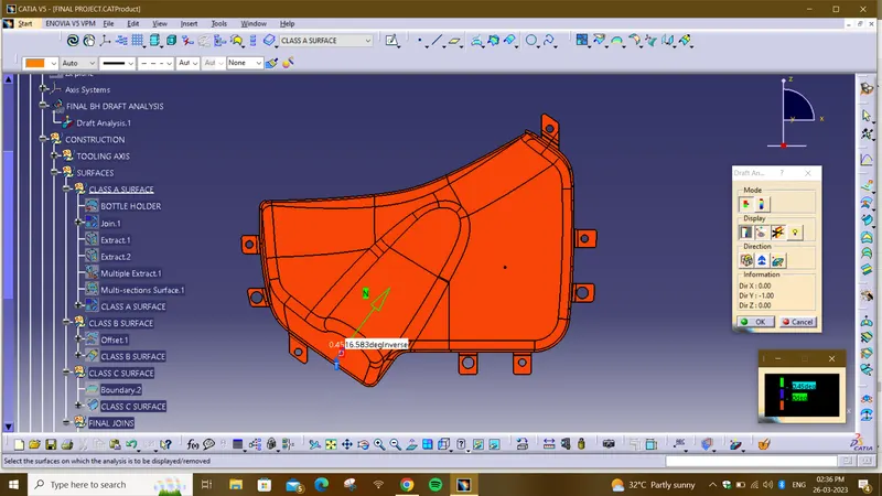
LEFT DRAFT VIEW
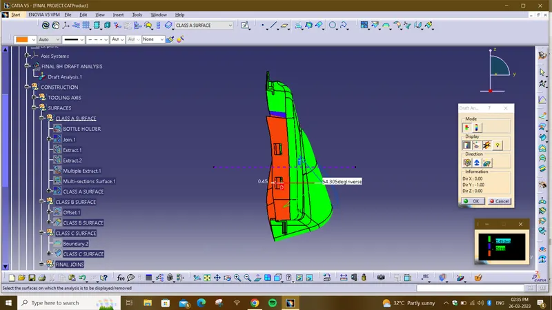
RIGHT DRAFT VIEW
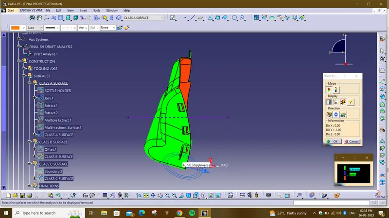
TREE STRUCTURE:
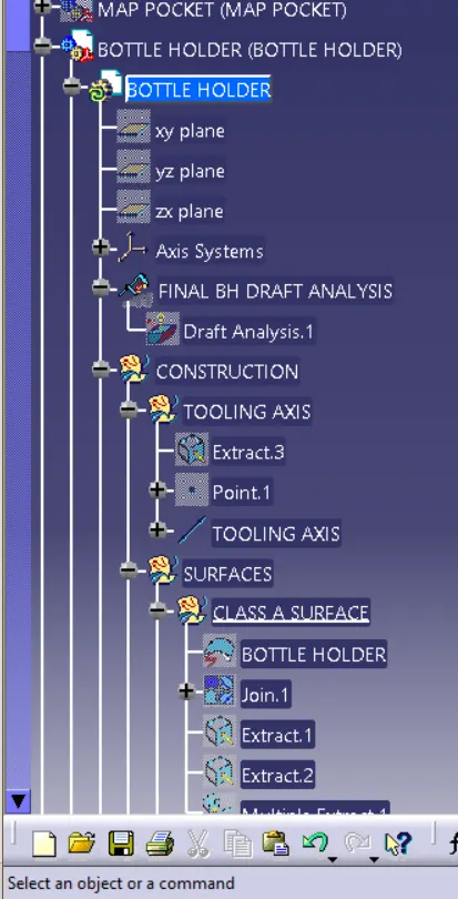
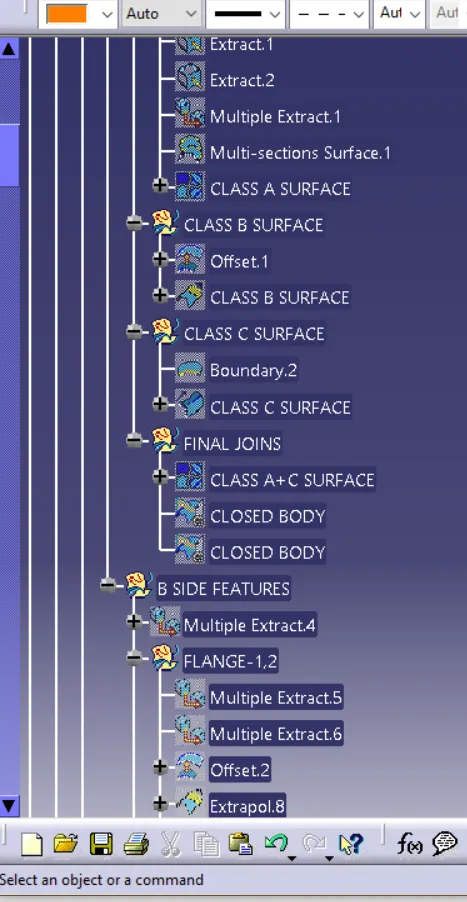
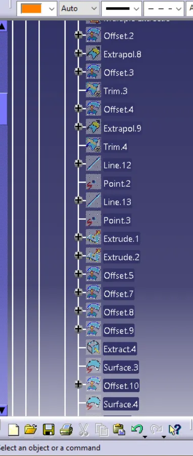
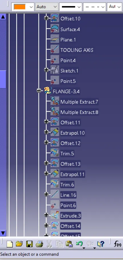
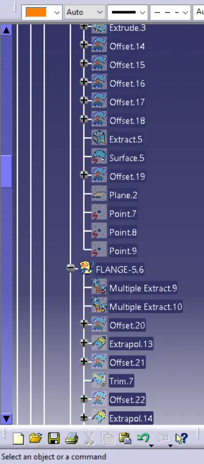
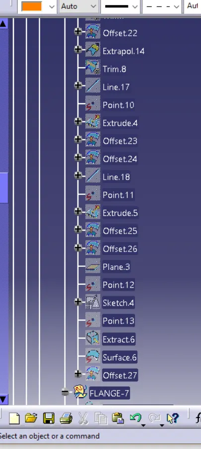
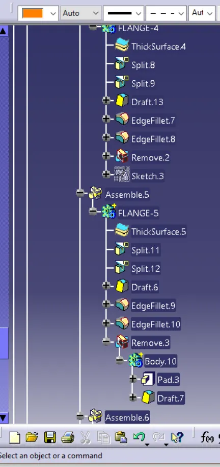
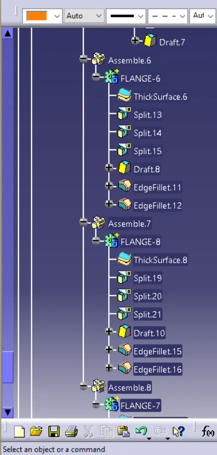
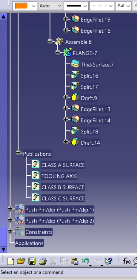
PUSH PINS
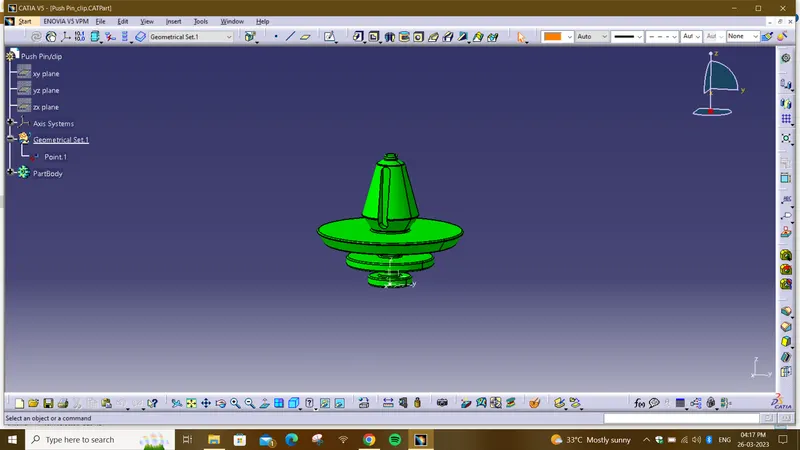
- These pins are used for the assembly purpose .
- These pins are guided into the sheet metal body.
- The pin is assembled over the dog house on one side and other into sheet metal.
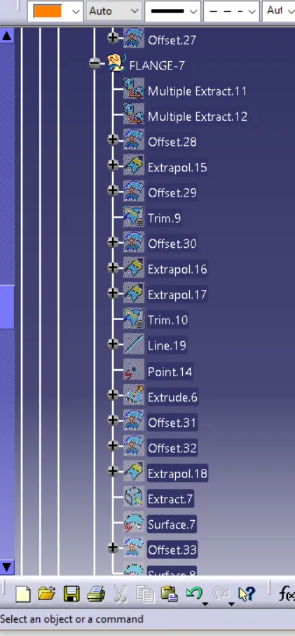
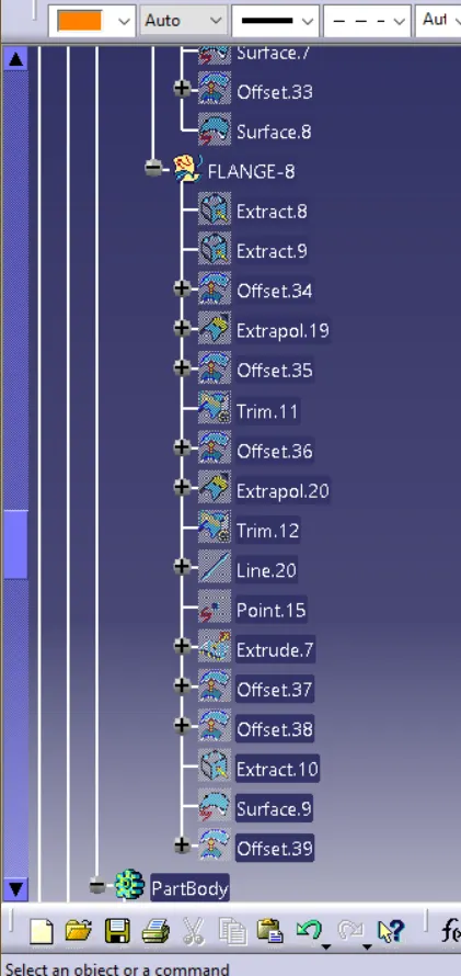
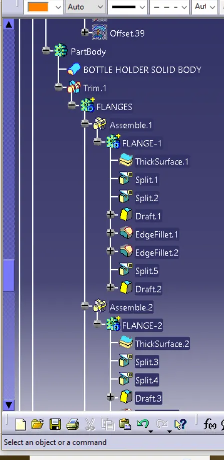
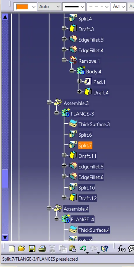
FLANGE:
The purpose of the flange was to provide slots for the heat stakes and locator which are required to assemble the two components together and constraint the motion between them. It is basically a counter part.
- These flanges will be build on the components for the fittment purpose with lower substrate.
- The hole at center will be guided along the heat stakes.
- Later top portion of the heat stake will be melted over it.
- The flange should rest on the supporting ribs on side .
FINAL ASSEMBLY:
The components that are created in separate part files and then inserted into assembly files they are assembled at their working position by applying constraints to them. To create an assembly using this approach, it is recommended to insert the first components and fix their position after properly orienting them in the 3D space the components can be inserted and positioned with reference to the first components.
DIFFERENT VIEWS OF FINAL ASSEMBLY:
ISOMETRIC VIEW
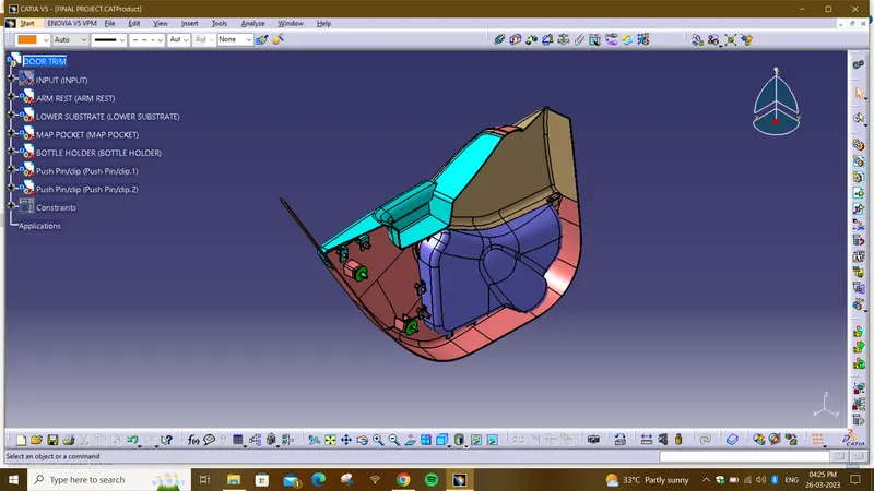
FRONT VIEW
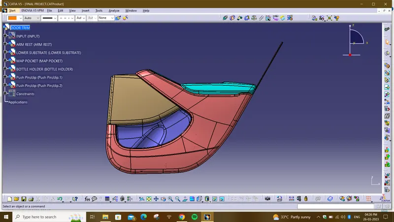
BACK VIEW
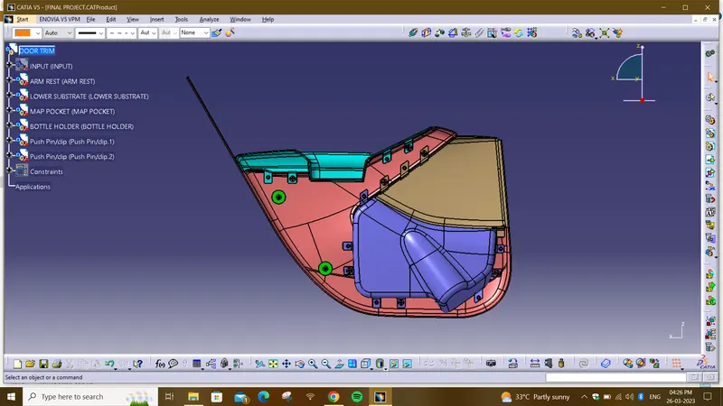
TOP VIEW
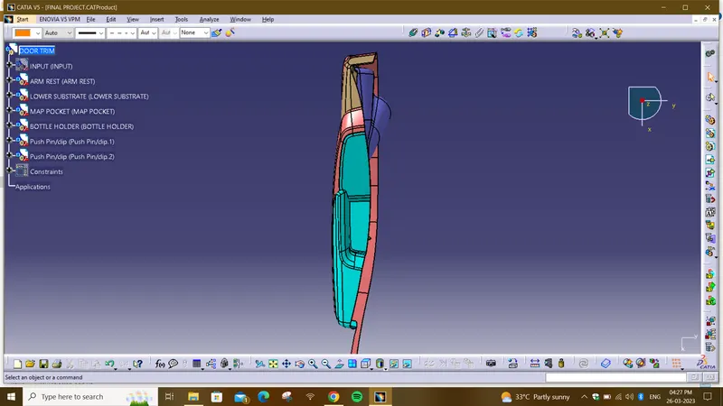
BOTTOM VIEW
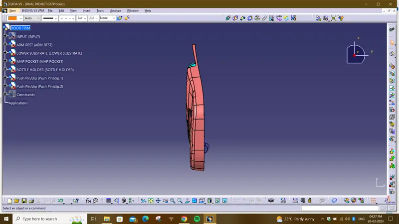
points observed:
- Arm rest class A surface is not proper there is a discontinuty at a edge.Hence it is modified.
- Arm rest does not clear the draft analysis with the single tooling axis. A side core tooling axis shold also be created for clearing the surface and flanges.
- Draft of 0.5 deg shold be provided to all flanges, heat stakes, locators.
- Dog house outer walls should have 1.5 deg draft and remaining inner walls should have a draft of 0.5degand must clear with side core tooling axis.
- Dog houses are oriented improperly because of uneven surface.
- Side flanges of the bottle holder has 0 deg draft hence not clearing the draft analysis.
- Orientation of bottle holder is not proper it bulges out of class a surface of lower substrate.
- Master section at some places has violated the design rules of the B-side featues.
CONCLUSION
The door Panel has been successfully designed by following OEM standards used in Automotive Industry. All the attachment features are properly placed at different locations.