Week 12- Final project
DEVELOPMENT OF DOOR TRIM PANEL
AIM: To develop the door trim (interior) panel with the given class A input and master sections using CATIA V5.
DOOR TRIM: The panel covers the inside of door trim where various electrical components of the car are connected. We design the plastic side of door trim panel which is attached th the sheet metal through various b side features.
The object is thickened to get the component which is suitable for manufacturing
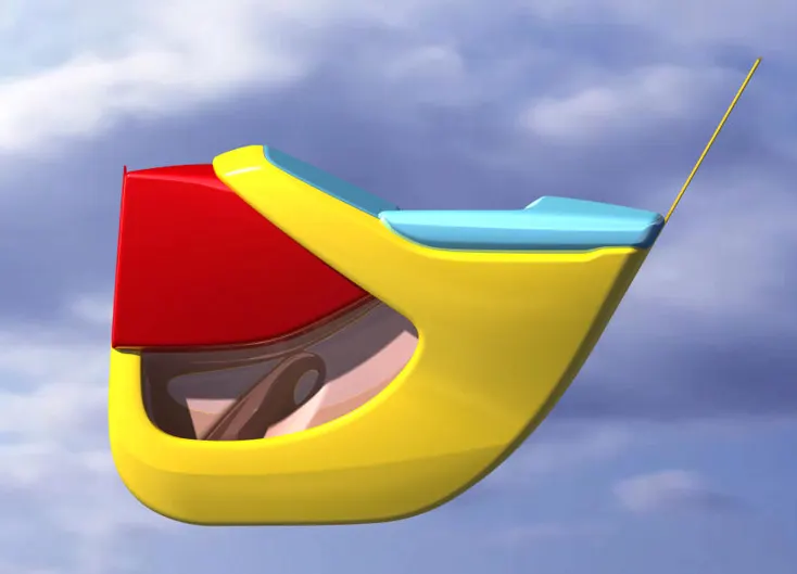
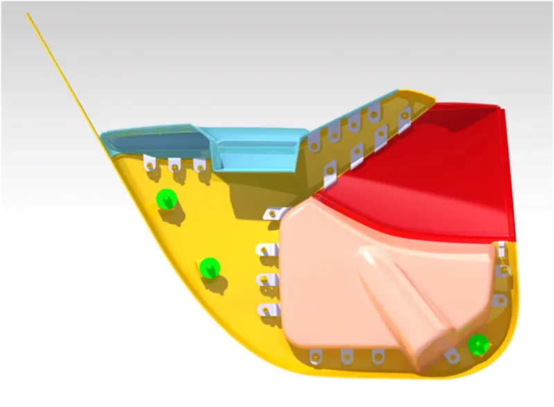
INTRODUCTION:
Door panels serve as an interface between the interior of the car and the inner workings of the door, and between vehicle occupants and the door. They are expected to meet a variety of design specifications regarding safety, aesthetics, and functionality. In addition, they are expected to continue the material theme of the dashboard and pillars while concealing intricate electrical and mechanical components for operating locks, windows, and other features. The door panel has evolved from a simple two-part system of latch and simple winding mechanism to a more sophisticated enclosure. Doors currently have an inner full-width panel consisting of electronic windows, central locking system, and speakers. These panels typically consist of a foamed core covered with either textiles or plastics..
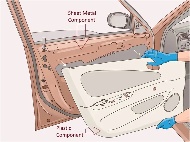
DOOR TRIM PANEL CONSISTS OF FOLLOWING COMPONENTS:
- DOOR ARM REST
- UPPER MAP POCKET
- LOWER MAP POCKET
- LOWER SUBSTRATE
- UPPER SUBSTRATE
- FLANGES
- HEAT STAKES
- DOG HOUSE
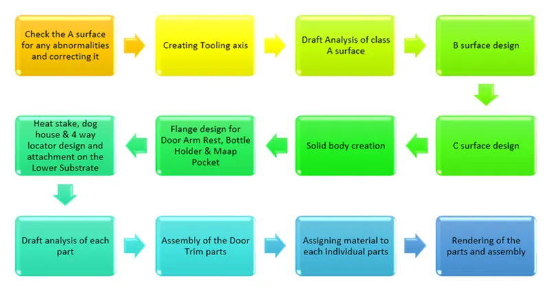
DESIGN METHODOLOGY
For this project we need to design four parts of the door trim using the master sections provided, namely
- Door Arm Rest
- Lower Substrate
- Bottle Holder
- Map Pocket
TERMS AND DEFINITIONS
CLASS A SURFACE
This is the styling surface which provides the aesthetic features of a component. A designer starts the component design from a class A surface.
CLASS B SURFACE
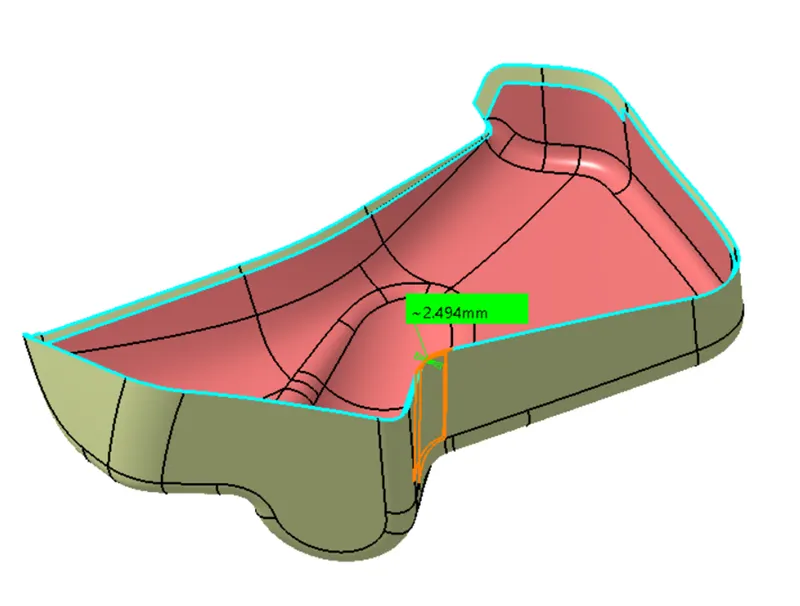
Class B surface is obtained by offsetting the class A surface by the component thickness value. This B surface contains all the engineering features of the component.
CLASS C SURFACE
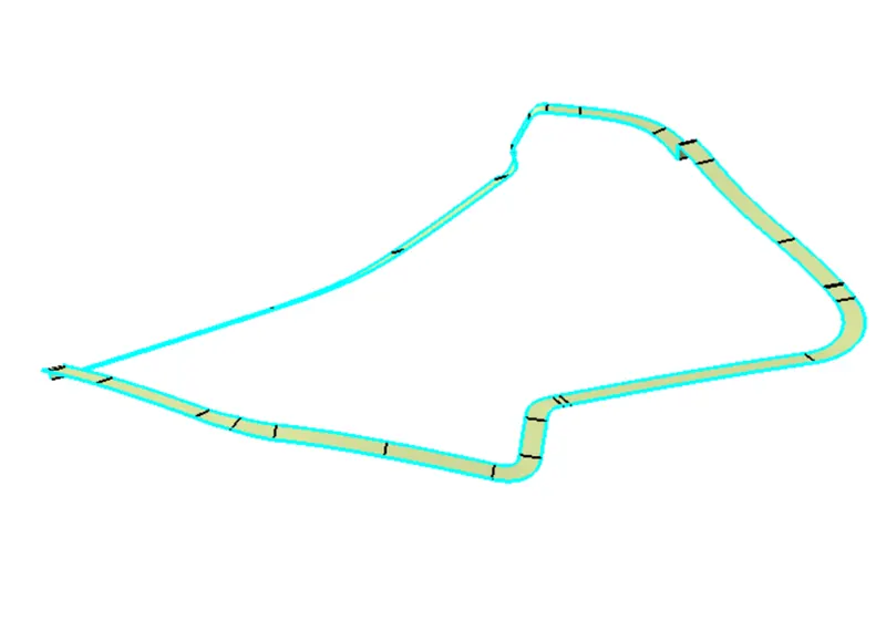
Class C surface is created along the tooling direction of the component and connects the class A and class B surfaces.
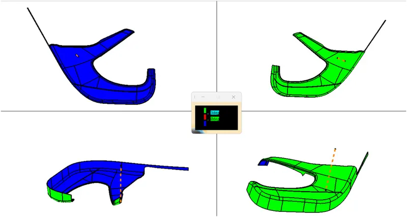
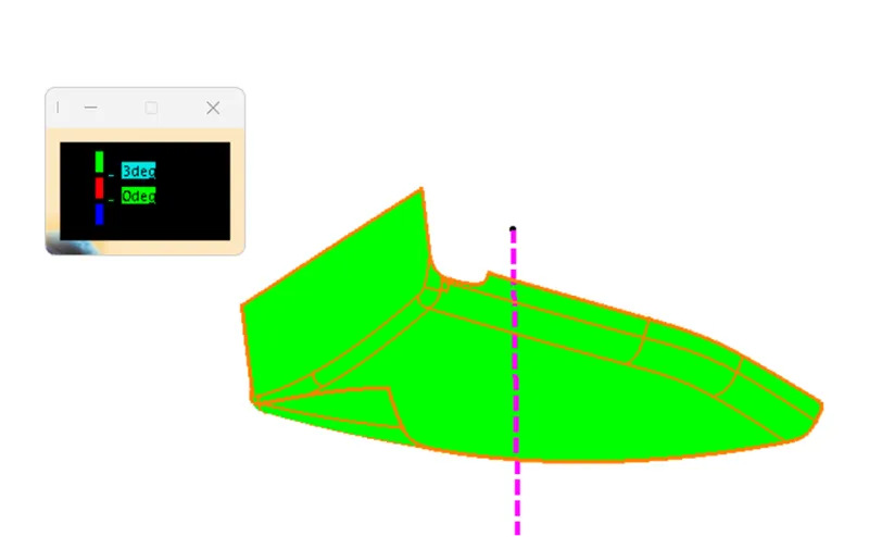
DRAFT ANGLE
Sheet metal and plastic parts that are made by forming, casting, pressing or even molding, require a draft angle at their side walls. Draft angles are the degree of taper that is incorporated into the side wall and cores of the die cast tool to aid in the removal of a part. Primarily, they function to reduce the friction between the part and the tool as it is ejected. Without draft angles, parts can be stripped, dented, or get stuck in the tool.
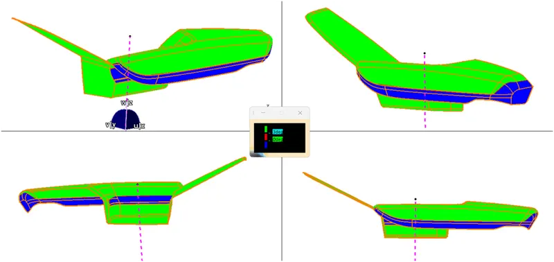
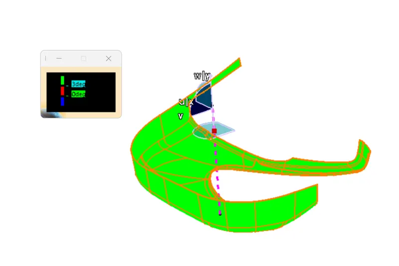
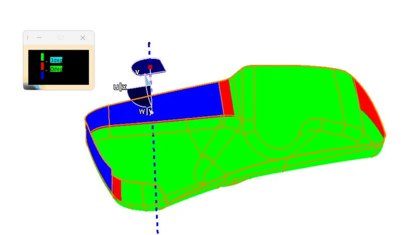
Draft angles are measured from the Tooling axis of the part. For mould designs where one metal mould component make direct contact with another, a minimum of 3° draft is required to ensure that the mould can separate properly.
DRAFT ANALYSIS
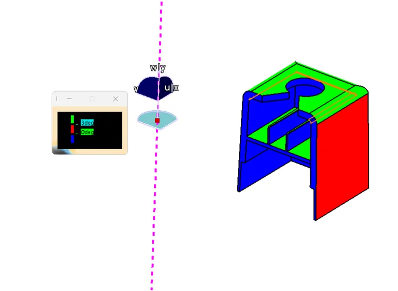
Draft analysis measures the draft angle on multiple surfaces of a part along the tooling axis to check if the surfaces have the minimum required draft angle for it to be moulded properly.
TOOLING AXIS
Tooling axis is the direction in which the 2 halves of a mould (core and cavity) opens or closes, or the direction in which the part is released from the mould.
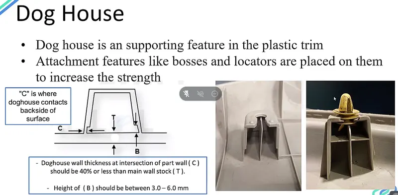
DOG HOUSE
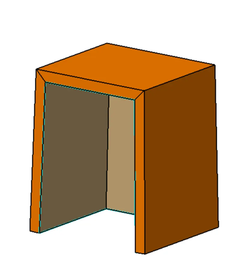
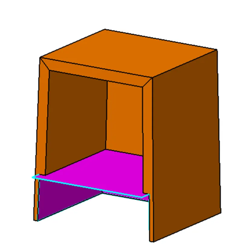
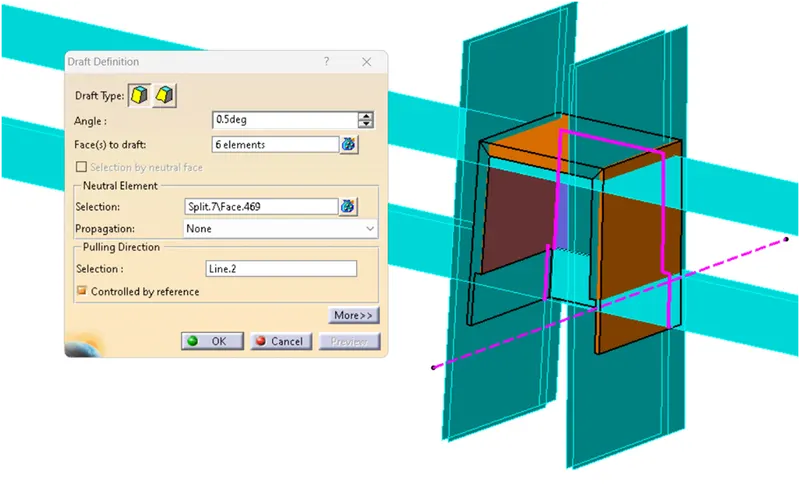
Dog house is an engineering feature used in plastic trim design. These are used as supporting feature and other engineering features such as bosses, locators etc are mounted on them to increase their strength. Dog houses require a slider for moulding and are subjected to draft analysis along the slider axis to prevent breakage during ejection from mould cavity.
HEAT STAKING USING HEAT STAKES
Heat staking technology is quite simple in concept. Whenever two or more components need to be attached to one another, and at least one is made of a thermoplastic, a combination of heat and pressure can be used to reform the plastic to the many shapes or profiles to retain or join the parts together.
This creates a solid, hardware-free bond that uses the plastic’s inherent strength to keep the finished assembly together.
4 WAY LOCATORS
4 way locators restrict 4 degrees of freedom along 2 axes of an object.
MAIN REPORT:
CLASS A SURFACES THAT ARE PROVIDED TO US:
- ARMREST:
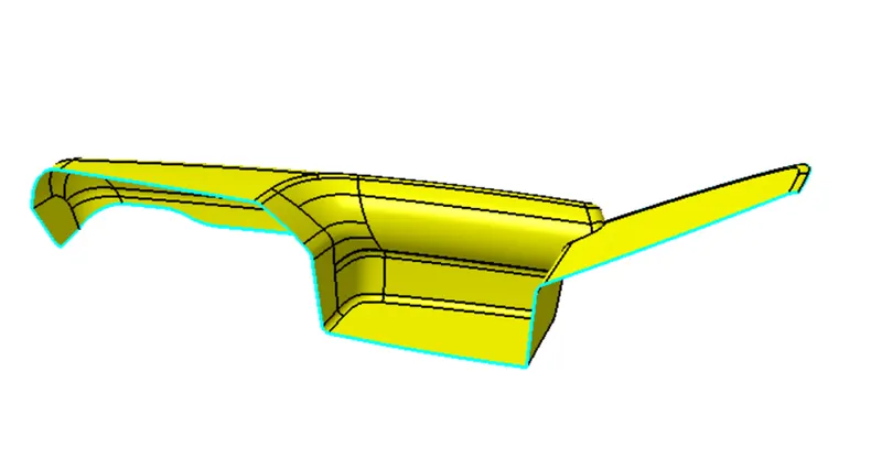
- LOWER SUBSTRATE:
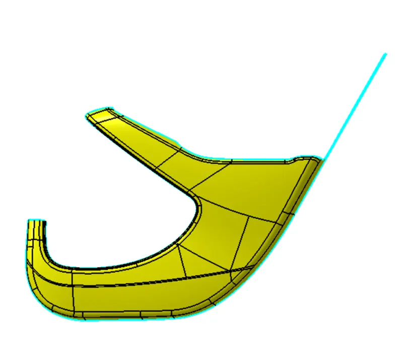
- MAP POCKET:
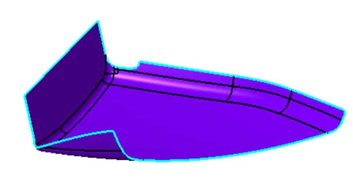
- BOTTLE HOLDER:
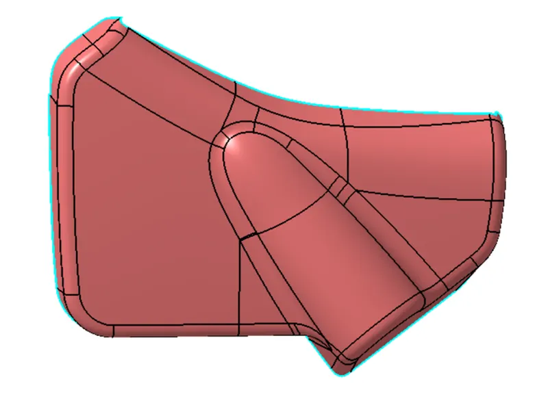
WHEN ALL OF THEM ARE VIEWED TOGETHER:
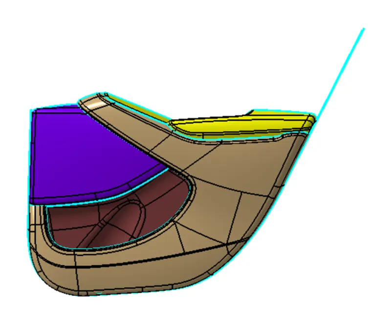
Now, we will begin by checking the State of Connectivity for the Class A Surface and ensure that there are no gaps between the surfaces as all the surfaces should be joined well together with each other and shouldn't consist of any discontinuities between them.
CREATE CLOSED SOLID BODIES
APPROACH:
Our basic approach to make a plastic model from class-A surface should be:
- Make tooling axis
- Run draft analysis
- Make B surface
- Make C surface
- Trim all together and make it solid.
1. ARM REST
CLASS A SURFACE
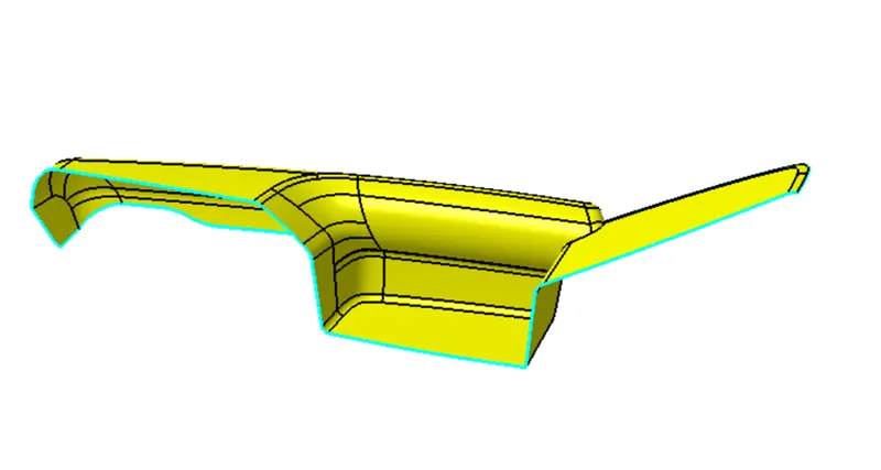
Using the 'Boundary' Command' from the Operations Toolbar:
In this case, we have to click on the 'Boundary' command and then select the Class-A Surface. After that, we'll click on the 'Preview' button to highlight all the boundaries that are on the Class-A surface and check if there are any internal boundaries other than the outer edge boundaries.
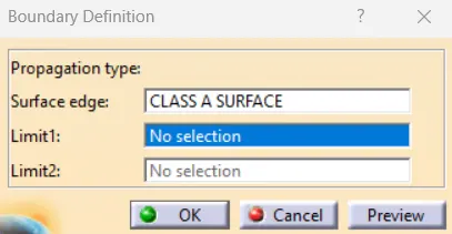
In our case, there are no 'Connexity Errors' for the given Class A Surfaces except in the Arm Rest's Class A Surface.
In case there is a 'Connexity Error', we can fix it by increasing the 'Merging-Distance' up to 0.003mm following the industry standard or we can perform other operations such as Extract, Trim, Join, etc.
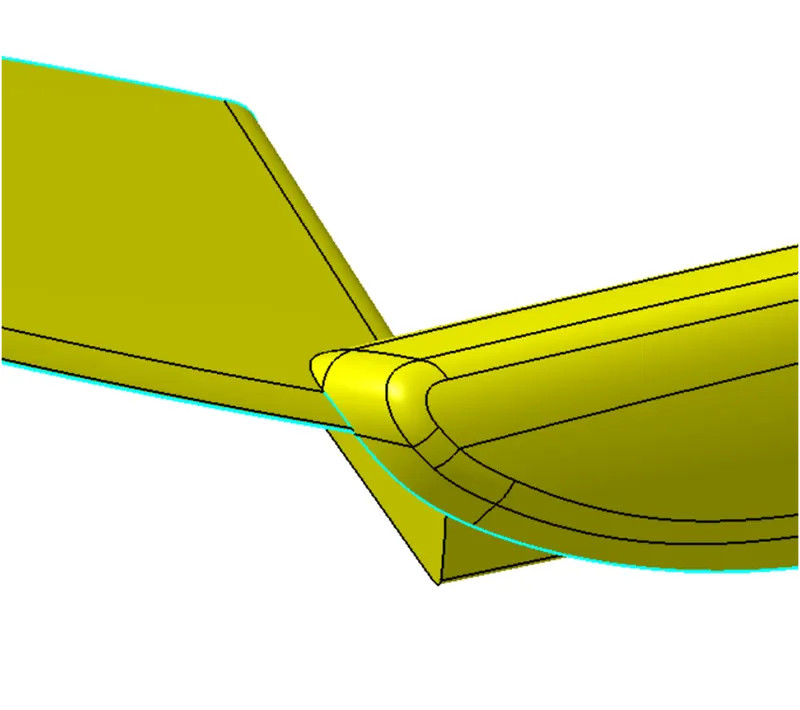
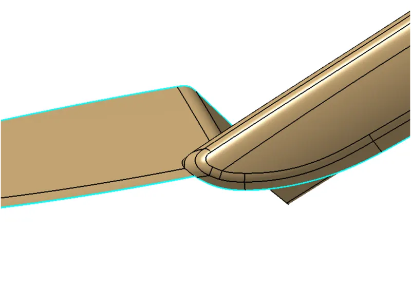
Here's the boundary error that we came across in the Arm Rest's Class A Surface. As we can notice from the image the boundary has extended to the interior section of the Arm Rest which is undesirable as we want to keep the along the outer edges only. Hence, now we're going to fix it.
NOTE: If there's an issue with the Class A Surface, firstly, we're required to report it to the Class A Surface Design Team first and let them know about the issues that we're facing with the Class A Surface and let them recreate or fix those surfaces but this is only possible in an industrial setting and our case, we're going to fix this on our own for now and proceed with the project.
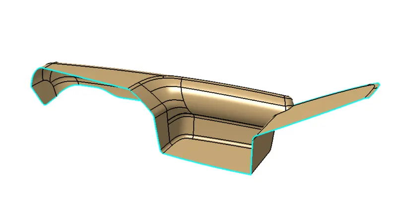
After that, we're going to create the necessary tooling axes for the Arm Rest Component using appropriate methods used in the industry such as bisecting method or choosing the direction from which the maximum amount of surface is visible for the component to be created.
IMPROVED CLASS A
DRAFT ANALYSIS
CLASS-B SURFACE
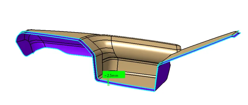
For that first Offset the A-surface for 2.5mm(according to master-section) and work on the patches if any are required.
Certain patches where missing while offsetting most of the surfaces so several procedures were done within the industrial rules and norms to obtain a fine CLASS B surface
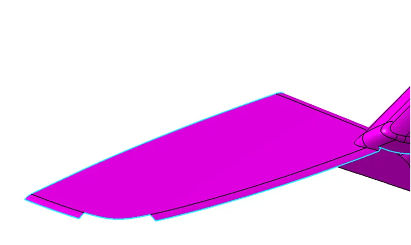
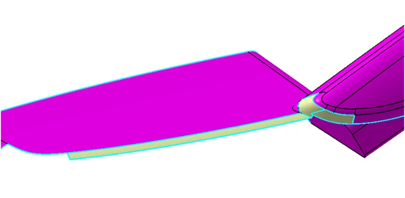
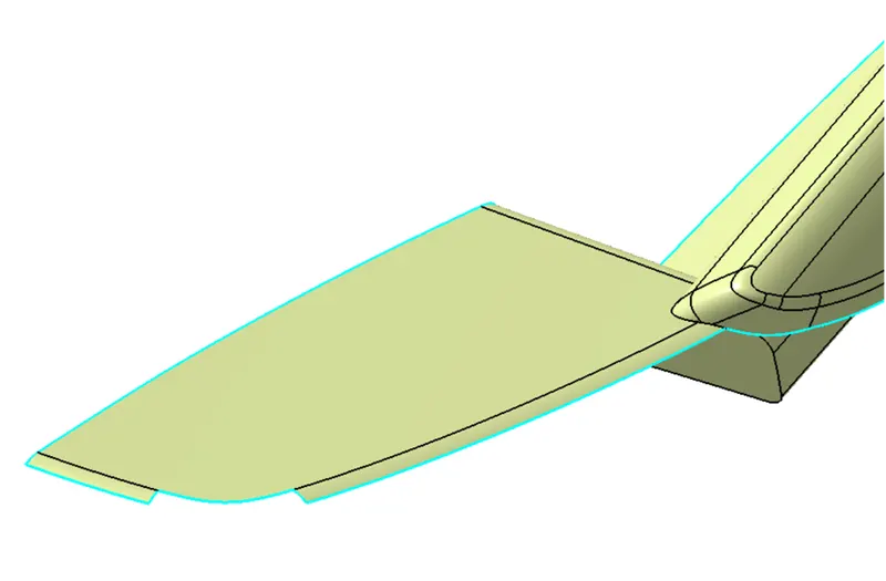
From the above image, we can see that it is not offsetting properly as some sub-elements of the surface will become erroneous which means they'll not get offsetted and hence we've to recreate them using various tools.
I found a problem with the surface as shown below and I'll fix it using various commands such as Extract, Extrapolate, Sweep, Trim, etc.
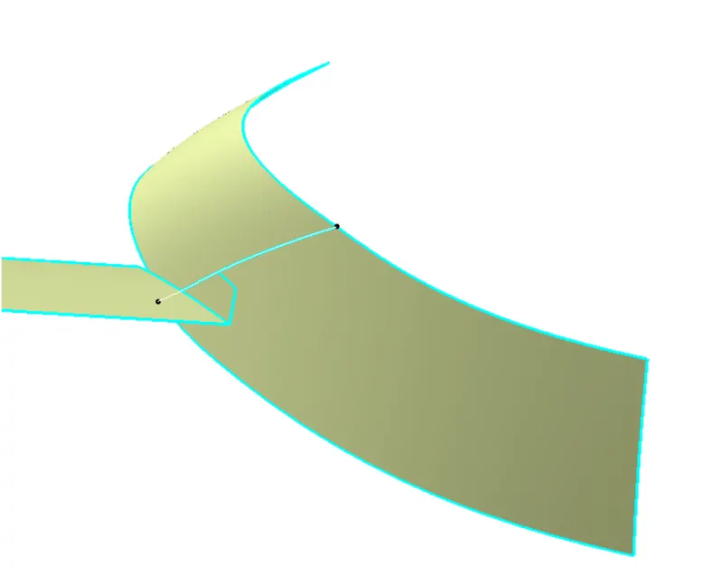
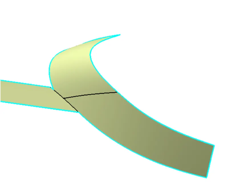
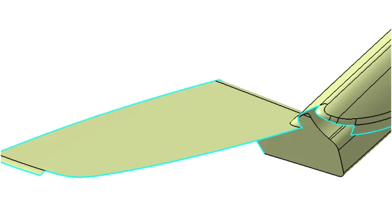
I used Multi-Section Surface to fix this issue as shown below:
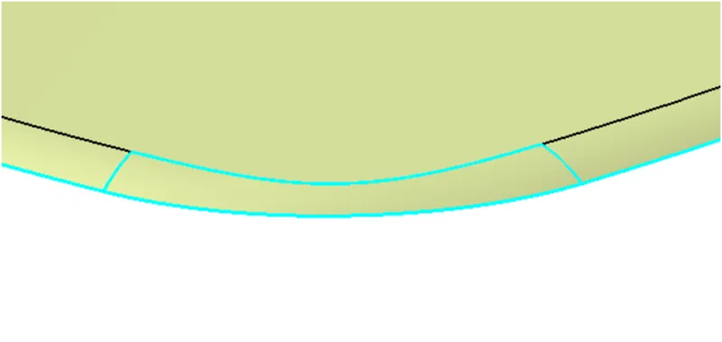
We'll join this surface with the offset surface
CLASS-C SURFACE
To generate the Class C Surface, the initial step is to unhide the Class A Surface and extract its boundaries using various commands. Among these, the Sweep Command with Draft Direction and Reference Surface is of utmost importance, as it allows us to create the desired surface by our requirements. Once the Class C Surface is created, we can merge it with the Class A Surface to form a single entity.
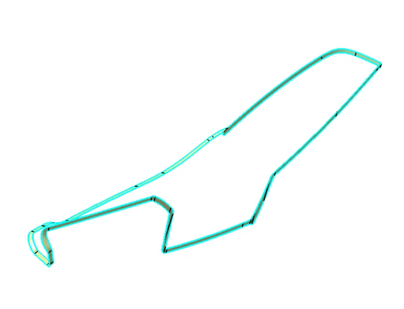
Next, we plan to merge the Class C Surface with the Class A Surface and create an intersection between the two with the Class B Surface. This will enable us to assess the feasibility of a Trim Operation between them. However, upon evaluation, we may find that the current intersection is not viable. In such cases, we will extend the Class B Surface and re-evaluate the feasibility of the Trim Operation.
To identify any issues with the intersection, we can utilize the Disassemble Command located under the Operations Toolbar. This will allow us to pinpoint any problem areas and rectify them accordingly.
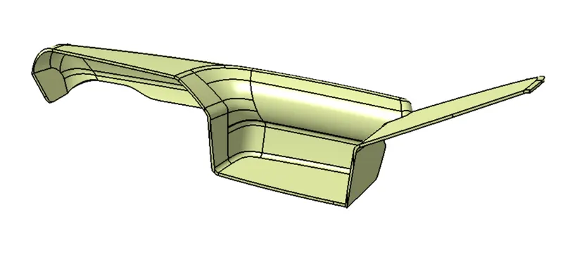
Upon successfully executing the Trim Operation, we will obtain a closed hollow body for the Arm Rest Component. To ensure that it is entirely enclosed, we will employ the Boundary Command. If the command fails to create a boundary around the body, it indicates that we have a completely closed body.
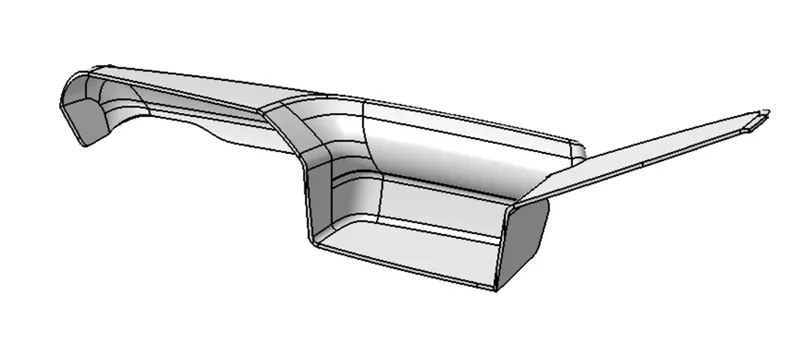
Subsequently, we will switch to the Park Workbench and utilize the Closed Body Command to convert the closed body into a Solid Body.
CLOSED SURFACE
SOLID ARM REST
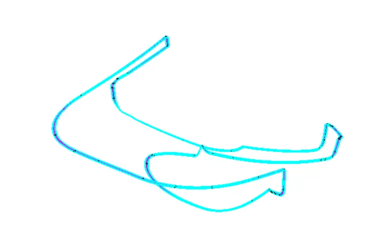
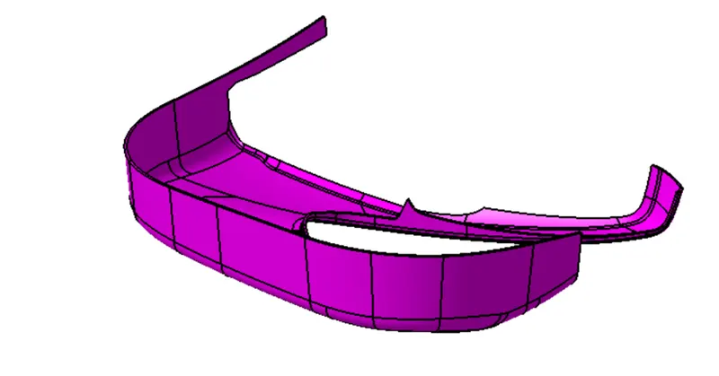
2. LOWER SUBSTRACT
CLASS-A SURFACE
DRAFT ANALYSIS
CLASS-B SURFACE
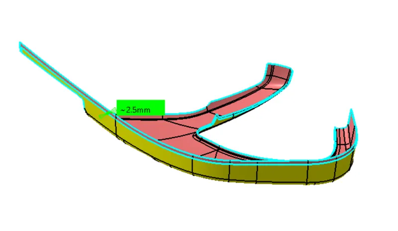
CLASS-C SURFACE
SOLID BODY
DRAFT ANALYSIS FOR SOLID BODY
3.MAP POCKET
CLASS-A SURFACE
DRAFT ANALYSIS
CLASS-B SURFACE
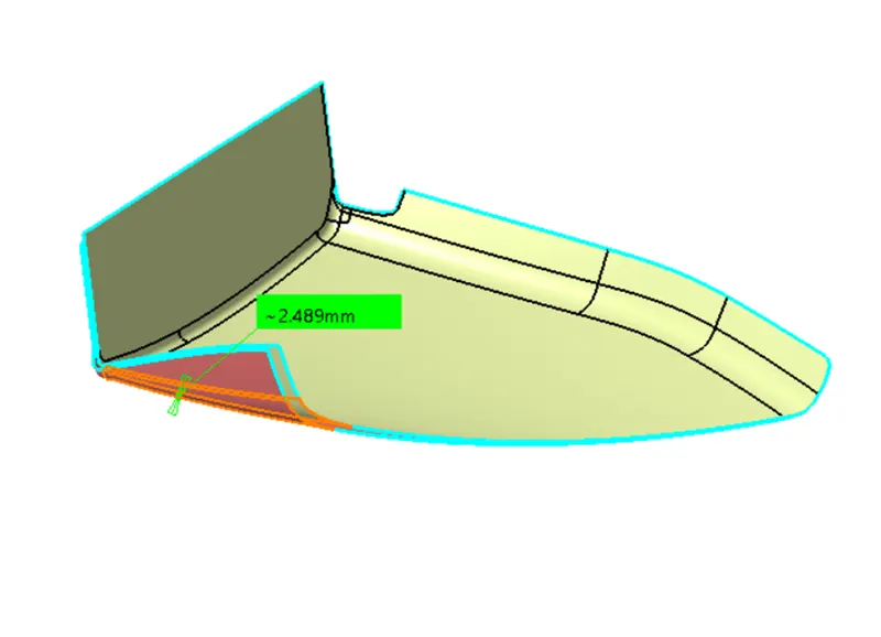
CLASS-C SURFACE
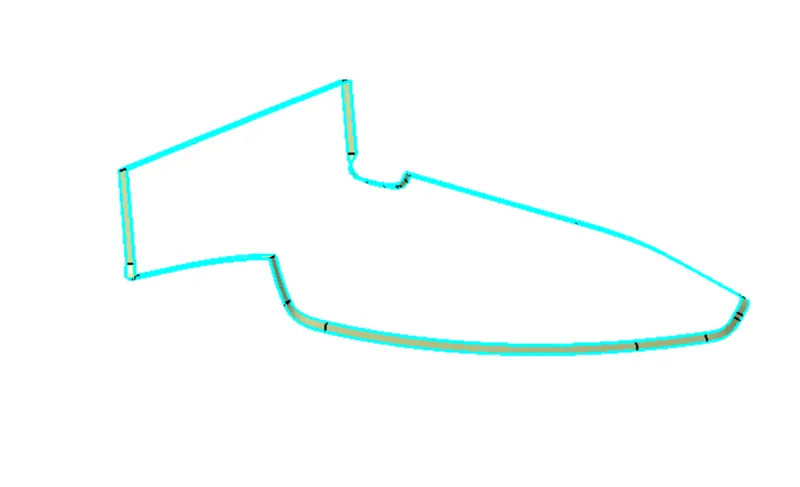
SOLID BODY
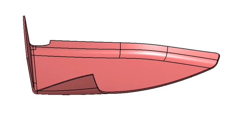
DRAFT ANALYSIS FOR SOLID BODY
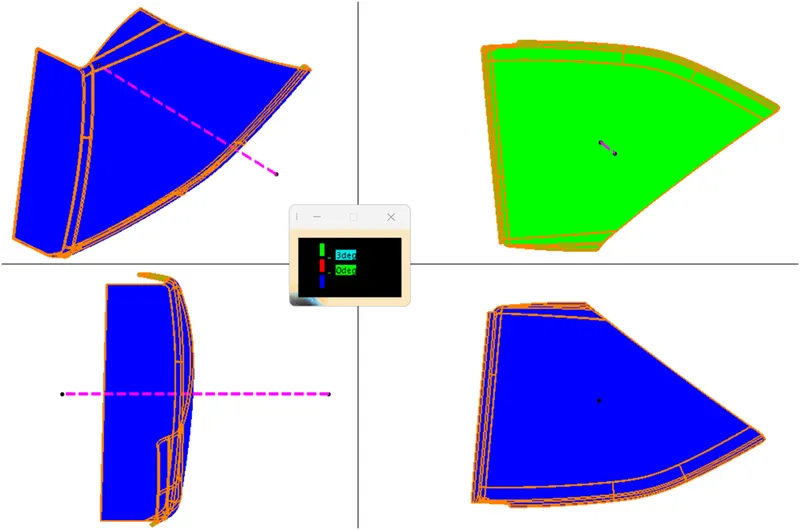
4.BOTTLE HOLDER
CLASS-A SURFACE
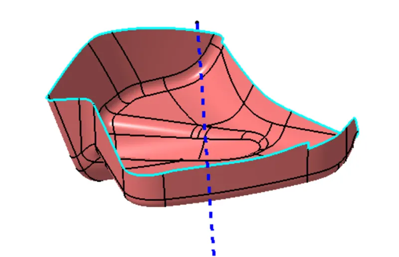
DRAFT ANALYSIS
CLASS-B SURFACE
CLASS-C SURFACE
SOLID BODY
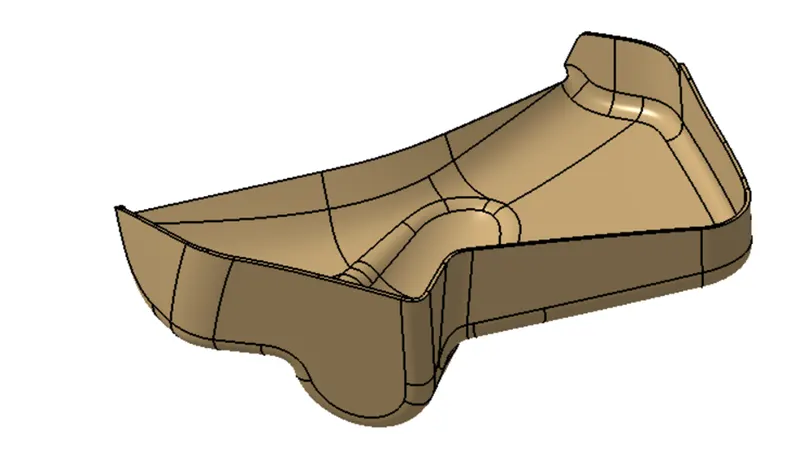
DRAFT ANALYSIS FOR SOLID BODY
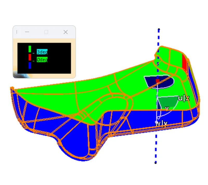
ADDITIONAL ENGINEERING FEATURES
- HEAT STAKES
- 4-WAY LOCATORS
- DOG HOUSE
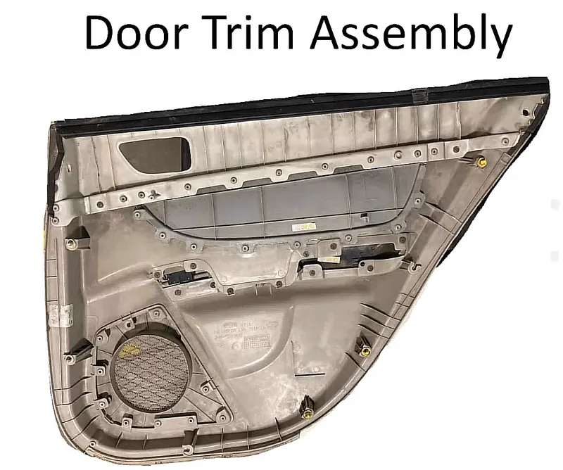
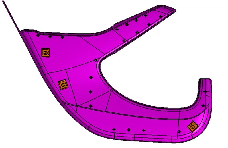
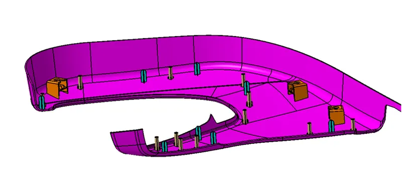
The above image showcases numerous engineering features incorporated into the design of the Door Trim to streamline the assembly process. Although the depicted components may differ from our own, this serves as an example of what our final product may resemble.
ROLE OF HEAT STAKES & LOCATORS IN THE PLASTIC DESIGN INDUSTRY:
Heat stakes and locators are commonly used in the plastic design industry to join plastic parts together, particularly in the automotive and electronics industries. Heat staking is a process of melting a small section of plastic and then forming it into a boss or protrusion to create a joint with another plastic part. Locators, on the other hand, are used to position and hold plastic parts in place during assembly.
Heat stakes are created by using a thermal tool to melt a small section of the plastic part, typically in the shape of a boss or post. The melted plastic is then formed into a protrusion or raised feature that can be used to create a joint with another plastic part. This process is often used for creating snap fits, which are designed to hold two parts together without the need for additional fasteners.
Heat staking can also be used to create airtight seals between plastic parts, as well as for inserting metal or plastic components into a plastic part. The process is relatively fast and inexpensive compared to other joining methods, making it a popular choice in industries where speed and cost are key factors.
Locators are used to position and hold plastic parts in place during assembly. They are typically small features on a plastic part that fit into corresponding holes or slots on another part, allowing for precise alignment during assembly. Locators can also be used to provide additional stability and support for plastic parts.
Overall, heat stakes and locators are important tools in the plastic design industry, allowing for efficient and cost-effective assembly of plastic parts. By using these techniques, designers can create strong, precise, and reliable joints between plastic parts, making them suitable for a wide range of applications.
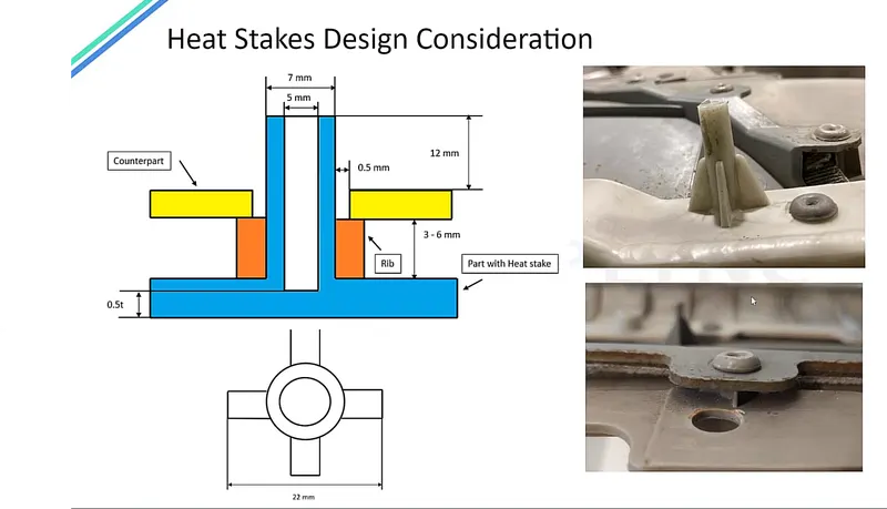
ROLE OF DOGHOUSE IN THE PLASTIC DESIGN INDUSTRY:
In the plastic design industry, the term "doghouse" typically refers to a raised area on a plastic part where heat stakes or locators are inserted. Heat stakes are small plastic studs that are heated and pressed into the doghouse to create a secure connection between two plastic parts. At the same time, locators are cylindrical posts used to align parts during assembly properly.
The doghouse provides a dedicated area on the plastic part for the heat stake or locator, allowing for precise placement and ensuring that the connection is secure. The raised area of the doghouse also helps to prevent the heat stake or locator from deforming the surrounding plastic during insertion.
Designing a doghouse involves determining the optimal size and shape for the heat stake or locator, as well as the placement and orientation of the doghouse on the part. Proper design and placement of the doghouse can help ensure the integrity and functionality of the assembled product.
Overall, the doghouse is an important element in plastic part design that facilitates the use of heat stakes and locators for secure and accurate assembly.
I will design an attachment strategy for the door trim by incorporating heat stakes, locators, and doghouses. These features will facilitate the assembly of various components with the door trim, including sheet metal components or other required parts.
To visualize this attachment strategy, I have included an image below. Generally, components such as switches, speakers, wiring harnesses, and airbag modules are added to the door trim plastic component.
It is crucial to ensure that the attachment strategy is implemented with precision and accuracy, as any flaws or inconsistencies could compromise the functionality and safety of the final product.
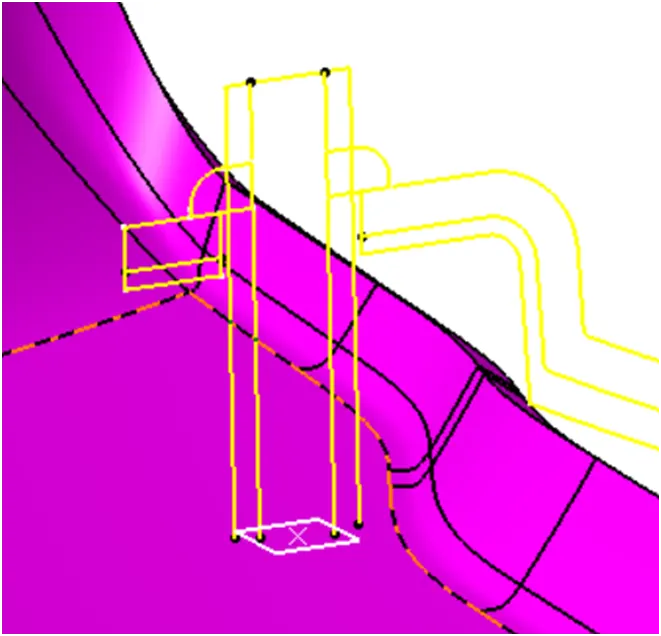
HEAT STAKE CREATION
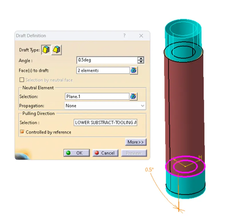
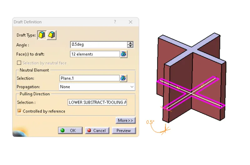
The heat stakes are the structures which are used for plastic welding.This is of permanant joint by using controlled melting.Heated thermal tip is used for this process,which is easy method of joining.The draft angle used for the heat stakes is 0.5 deg.this image shows the heat stake with reference to the master section.
DRAFT
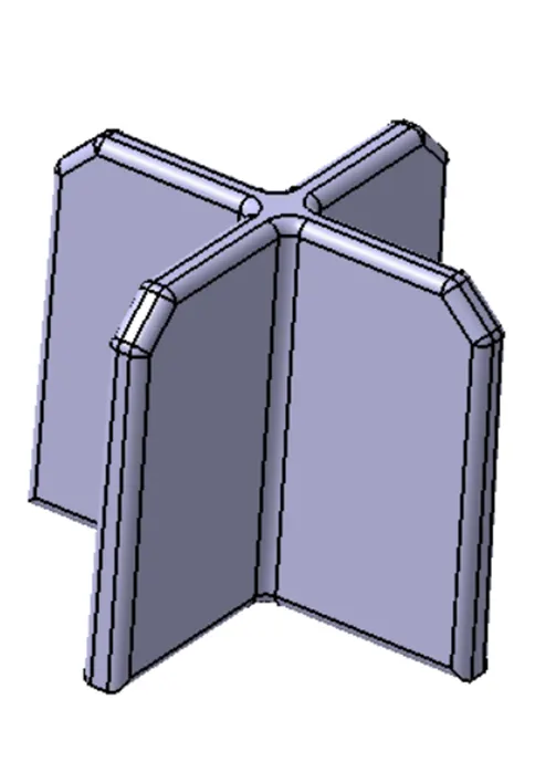
AFTER UNION TRIM
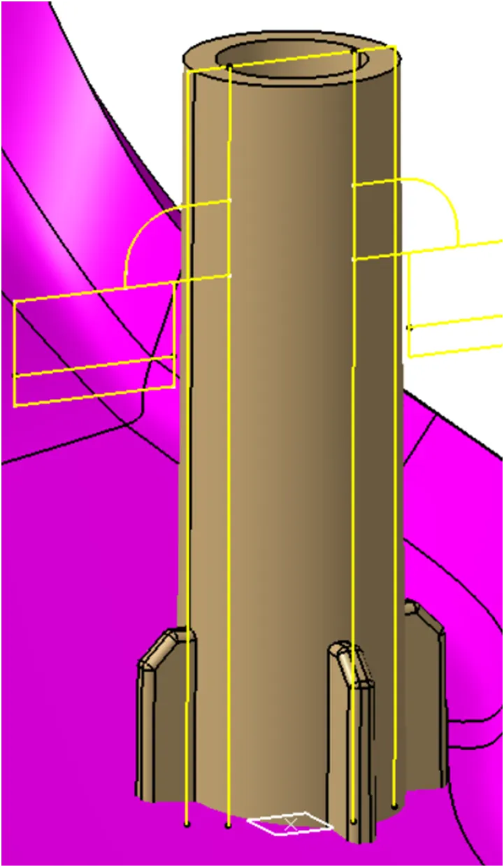
Design rules for Rib creation (and 4 way locators)
RIBS:
The ribs are supporting structures which gives strength to the thin surface.It should be connected to other structural features.The draft angle for the rib is 0.5 deg,advisable fillet radius is 0.25-1 mm.The design guideline for the rib creation is shown below.
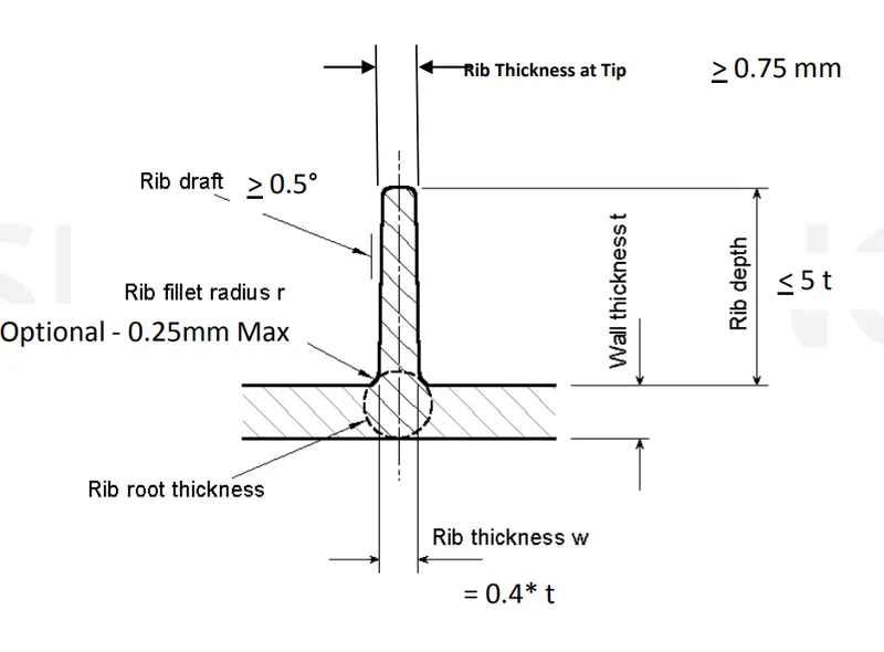
- Draft – minimum of 0.5° per side
- Thickness – generally 40% of wall thickness
- Thickness of Tip – minimum of 0.75mm
- Radii – maximum of 0.25
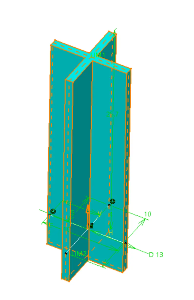
4 way locator
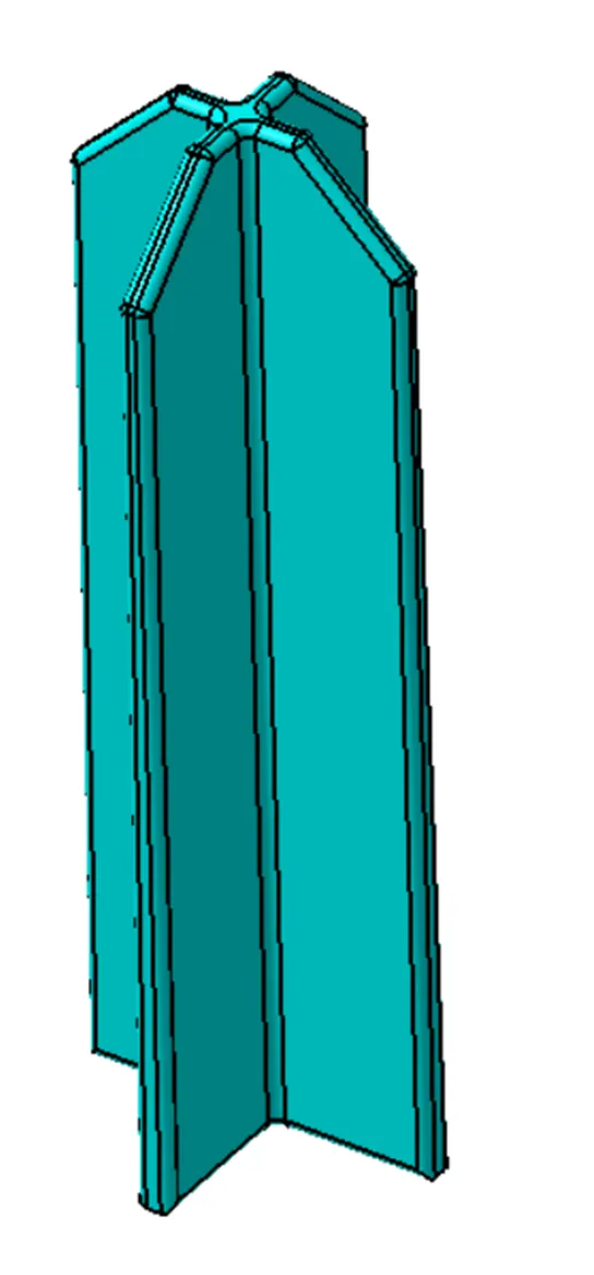
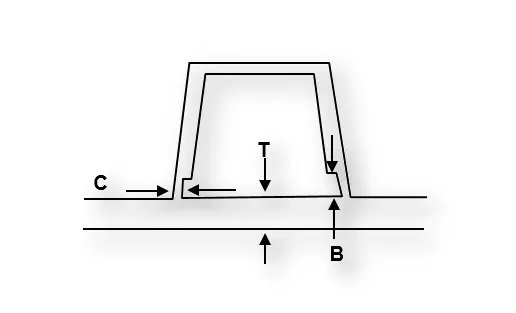
DOG HOUSE: Primary function of the dog house is to avoid sink marks. But it also helps in other things like if the mating part is to be at a greater distance then we cannot make the height of the screw boss of that greater height, thus we make dog house and mount screw boss on it. Hence it helps in solving the problem of screw boss and also it helps to have perpendicular screw boss.
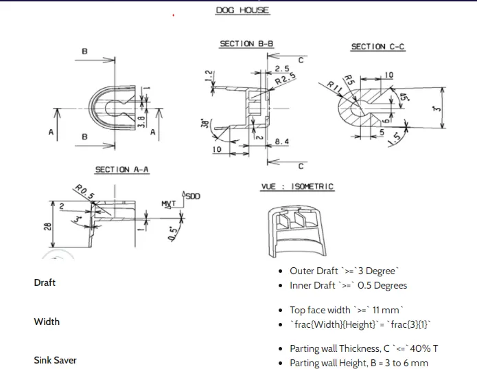
GENERAL DESIGN GUIDELINES FOR DOG HOUSE DESIGN:
- Minimum height: Less than 6mm causes steel condition.
- 3:1 ratio of steel width to height. But 2:1 is preferred.
- Minimum width: 3:1 ratio of steel width to height. But 2:1 is preferred.
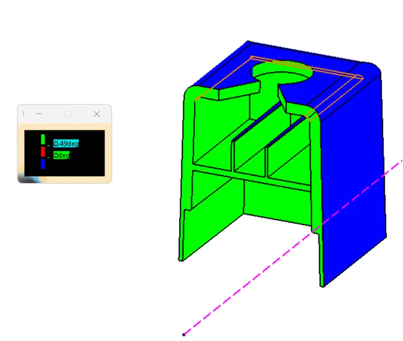
- Draft: minimum 1.5deg.
- Sink saver: height= 40% of nominal thickness. Width= 3.0mm-6.0mm.
- Optimal radius:25mm
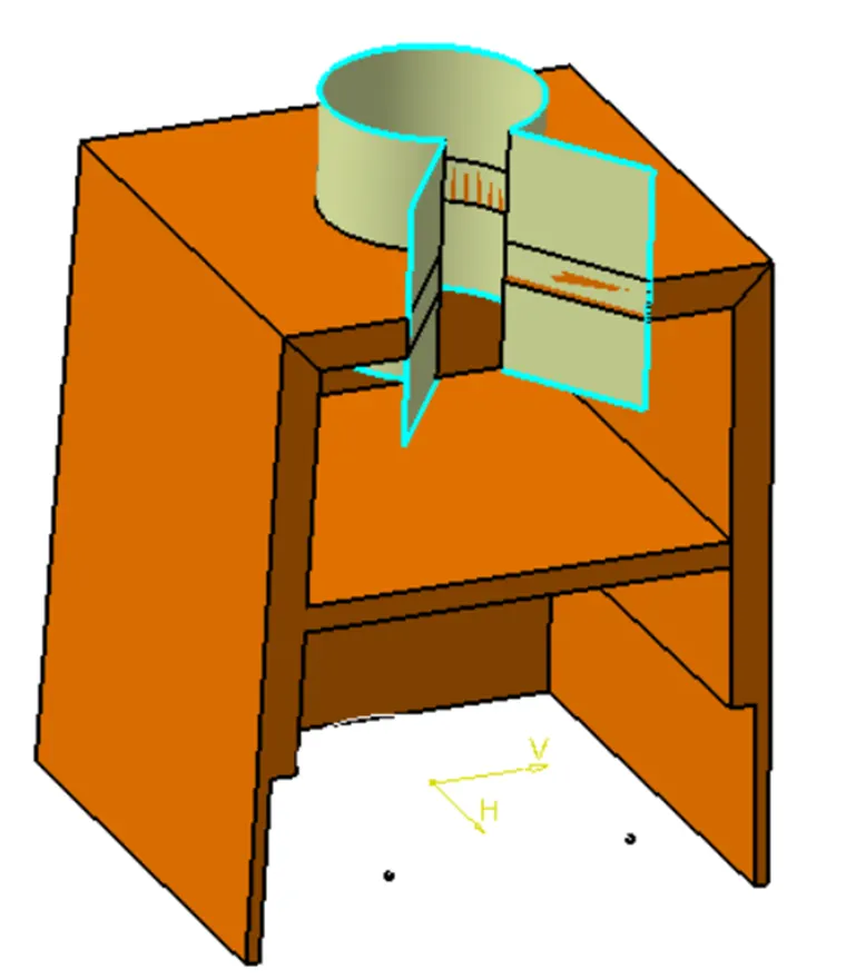
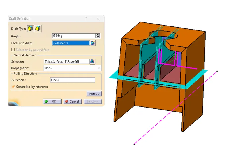
FINAL DOG HOUSE
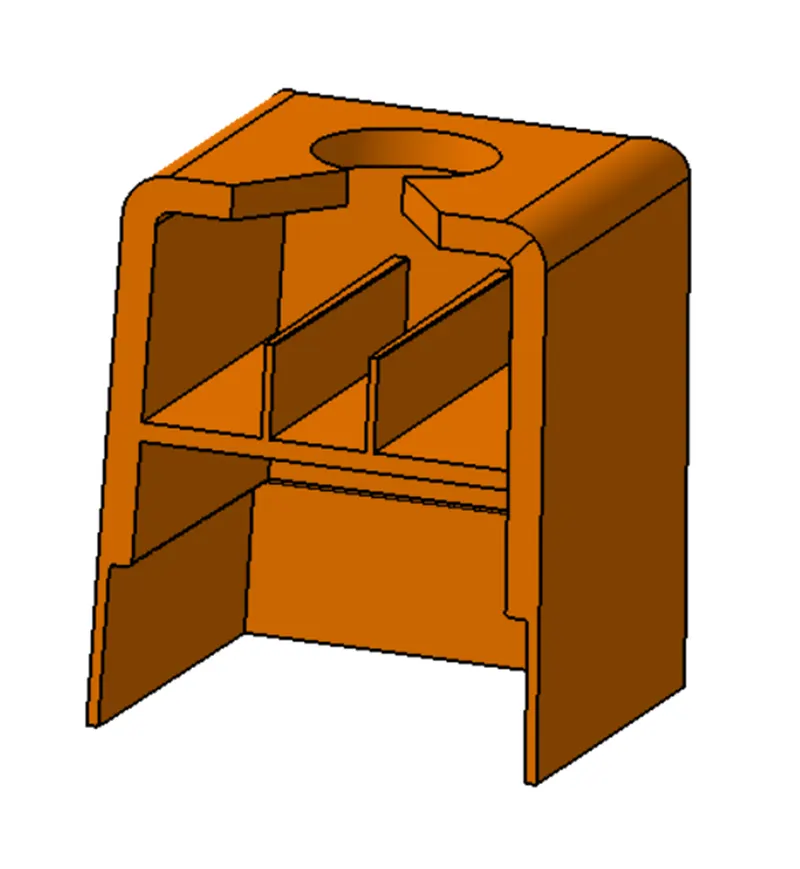
DRAFT ANALYSIS (DOG HOUSE)
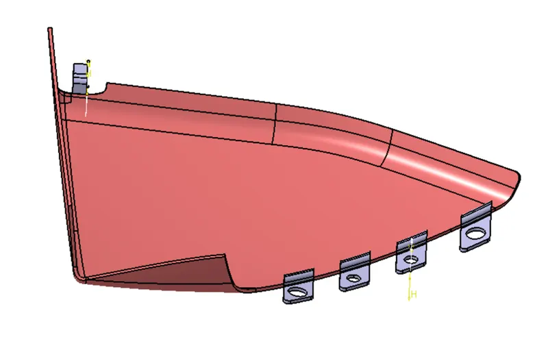
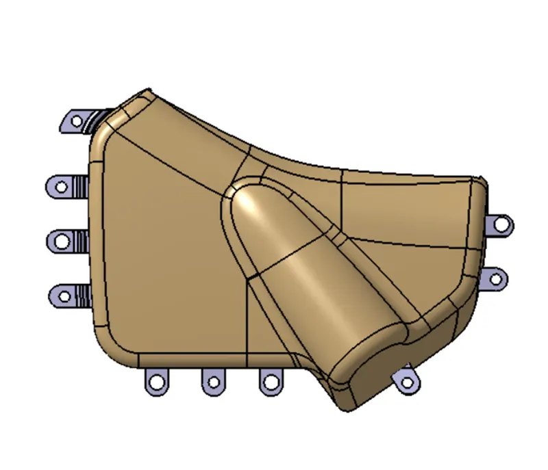
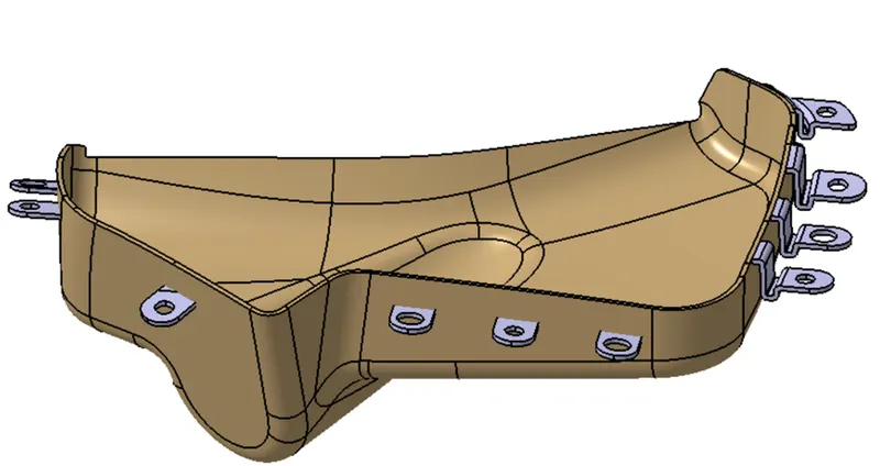
PROCEDURE TO CREATE THE COUNTERPARTS (FLANGES):
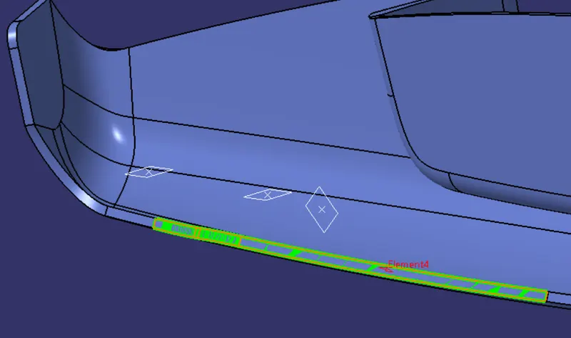
To begin with, our objective is to produce the flanges for the Arm-Rest Component, adhering to the Master Section guidelines for each specific part in relation to the Lower Substrate. As illustrated below, our first step in achieving this is to extract the C-Surface from the Final Trim between Class A+C and B.
Next, we will utilize the Master Section to generate a plane using the Three Point Command. This plane will intersect with the previously extracted C-Surface, enabling us to establish the intersection point. Ultimately, this intersection point will serve as a crucial reference point for creating the flanges with respect to the Lower Substrate. The visual representation of the plane and intersection point is depicted below.
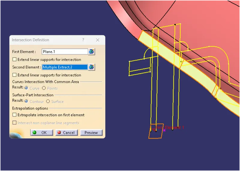
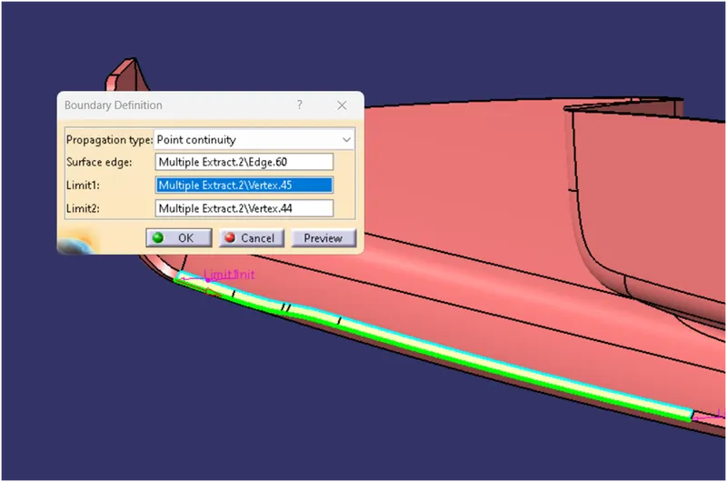
Then, we'll extract the boundary from the extract c-surface that can be used as a guide curve eventually to create surfaces for these flanges.
Then, we're going to create two sketches with respect to the master section as shown below:
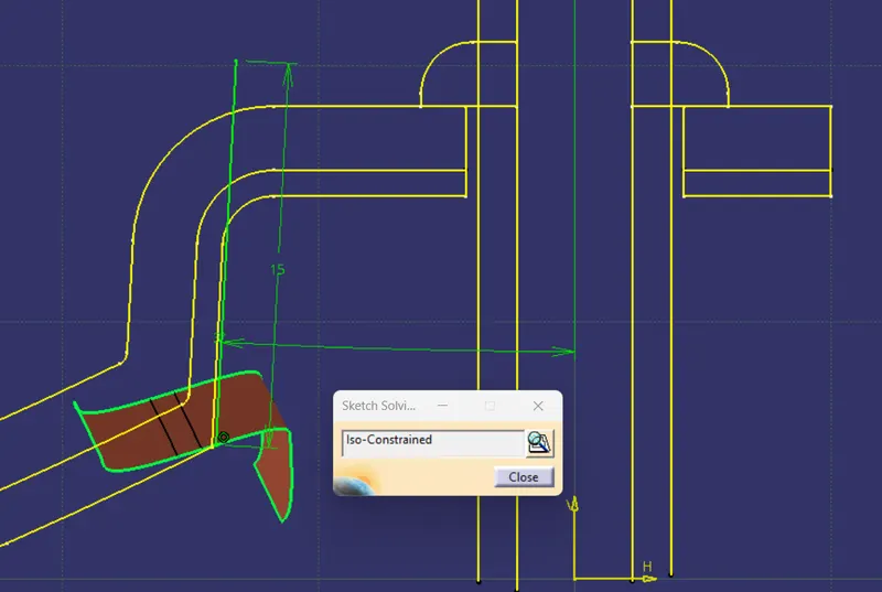
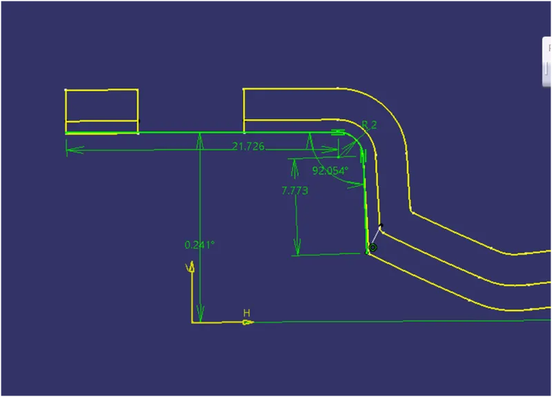
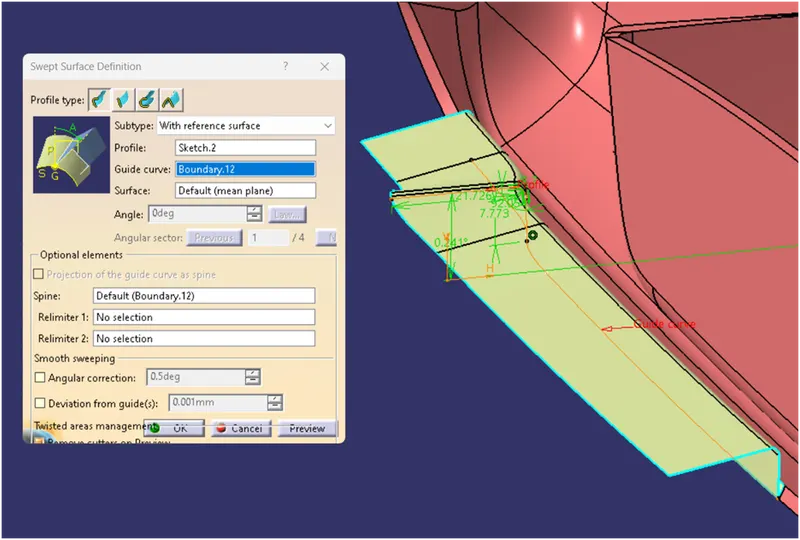
To proceed, we will utilize the Sweep Command and choose the 'With Reference Surface' subtype. We will then select the sketch that originates from the intersection point we previously established, and employ the extracted c-surface boundary as our guide curve to generate a surface. The resulting outcome is demonstrated below.
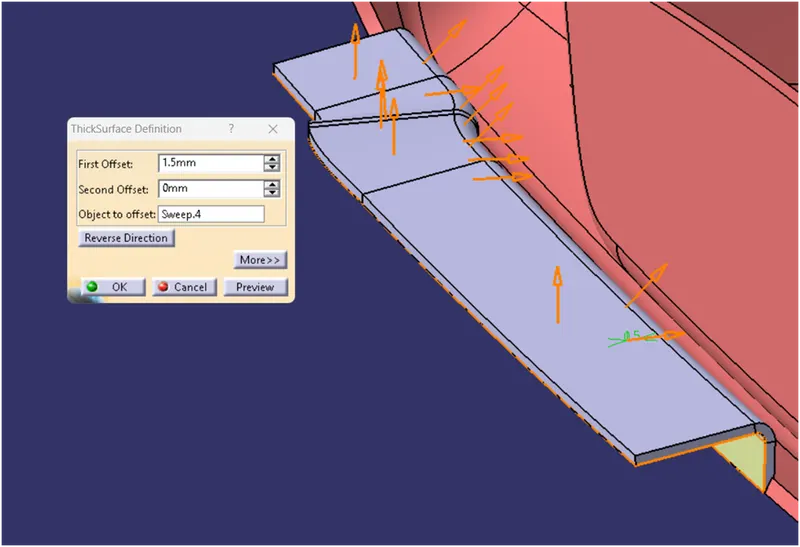
Then, we'll use the Thicken Command on the trimmed surface from the Part Workbench as shown below:
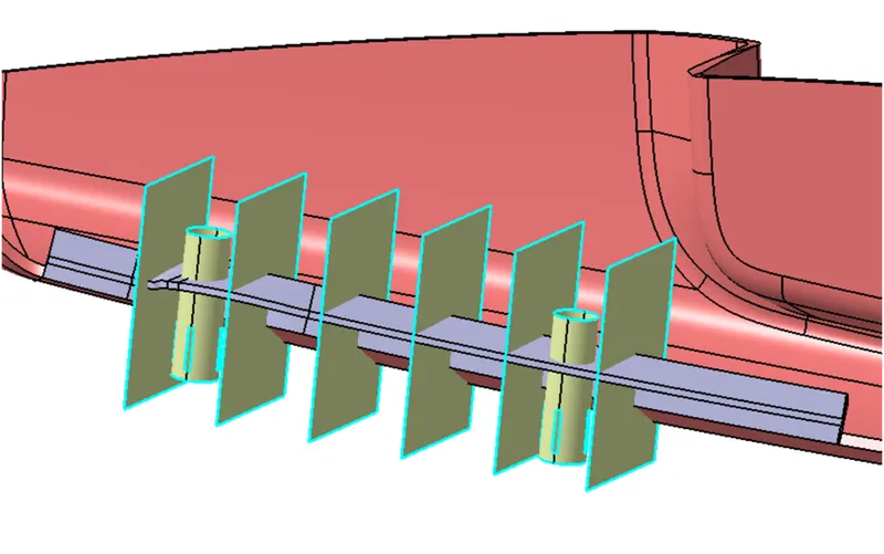
Using SPLIT command to split the Flanges
ARM REST WITH FLANGES
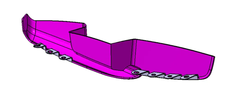
MAP POCKET WITH FLANGES
BOTTLE HOLDER WITH FLANGES
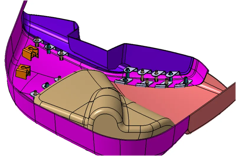
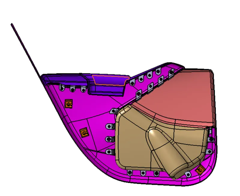
PROCEDURE FOR ASSEMBLY OPERATION:
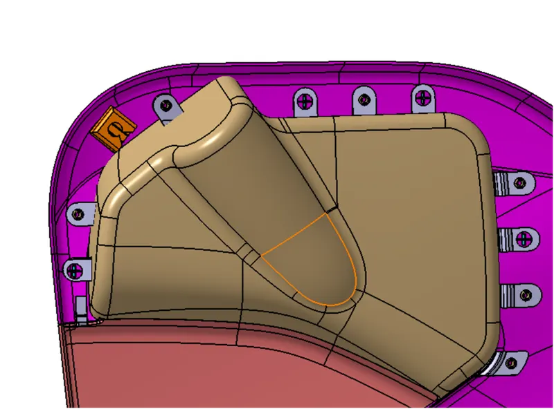
In the final step of the assembly process, we will utilize the Assembly Workbench to bring all of the individual components together. We will start by creating a point and using the Coincidence Constraint from the Constraints Toolbar to ensure that the components are assembled precisely and accurately. This will guarantee that the final product will function seamlessly, without any misalignment or errors.
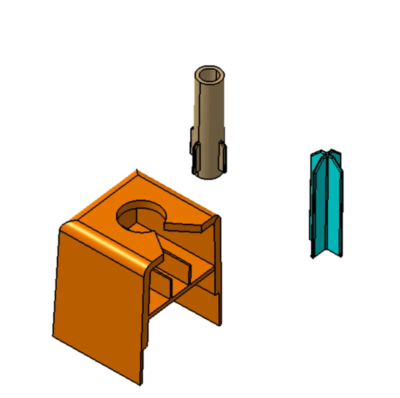
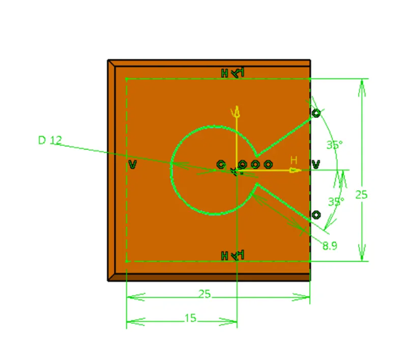
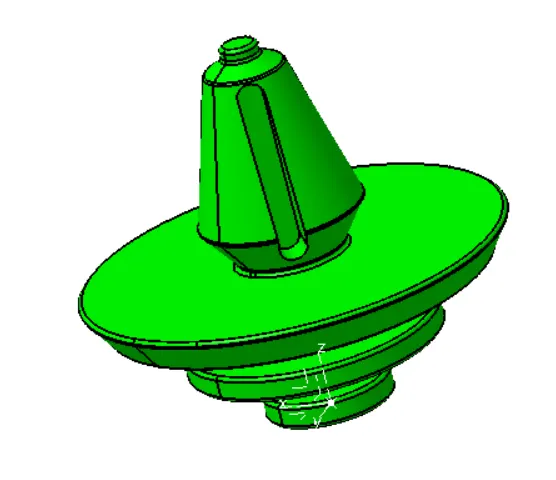
Furthermore, we have been provided with a Push Pin body that needs to be seamlessly integrated into the Keyhole on the Doghouse. Using the same set of tools, we will carefully assemble the Push Pin into the Keyhole to ensure that it fits securely and functions properly. This will be a crucial step in the assembly process, as it will determine the overall stability and durability of the final product.
PUSH PIN:
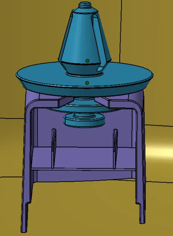
To verify that all of the components have been properly constrained, we will utilize the Move Toolbar and the Manipulation Command. This command enables us to move the components along the X, Y, or Z-axis, according to our preferences. Once we have moved the components, we will click on the Manual Update button to see if they align in their respective positions as per our initial constraints.
This step is crucial to ensure that all the components have been constrained correctly and will function seamlessly when assembled. It provides an extra layer of assurance that the final product will work flawlessly without any issues. By carefully manipulating and verifying the position of each component, we can guarantee the high quality and reliability of our final product.
The required CATparts & CATproduct files are attached to this report.