Week 10 - Challenge 1- Attachment Feature Creation (Ribs & Screw Boss)
Attachment Feature Creation (Ribs & Screw Boss)
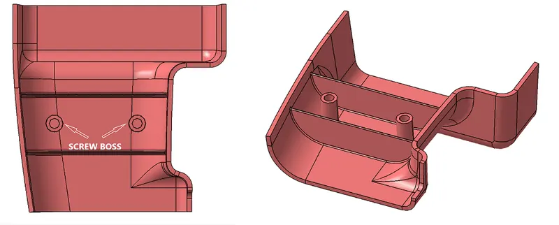
AIM:
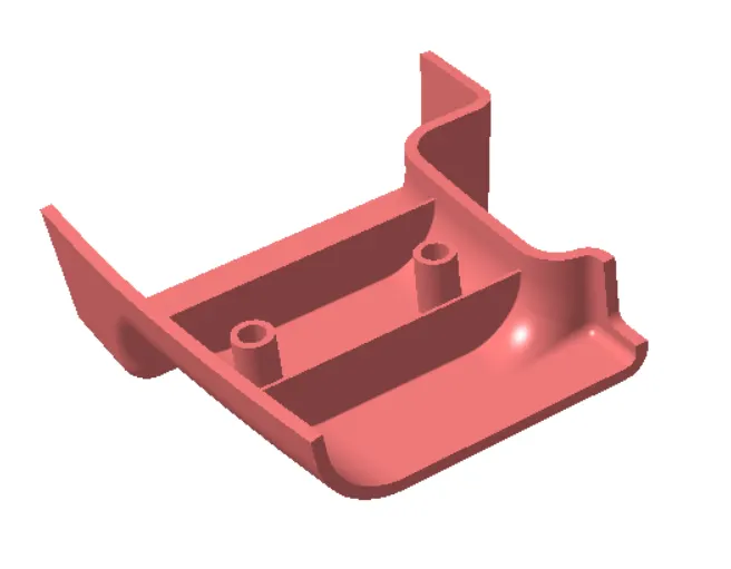
- To Create the Door Handle Component from the given Class-A surface.
- To Create the tooling axis for the given Class-A Surface meeting the requirements of the draft angle.
- To Attach B side Features in the component.
- To perform the Draft analysis on the model.
TOOLS USED:
- Boundary
- Join
- Multiple extract
- Bisecting line
- Trim
- Surface offset
- Draft analysis
- Intersect
- Surface sweep
- Close body surface
Class A Surface:
To start the design process we need to find out the tooling axis for the surface and check the drafts using the Draft Analysis tool in CATIA.
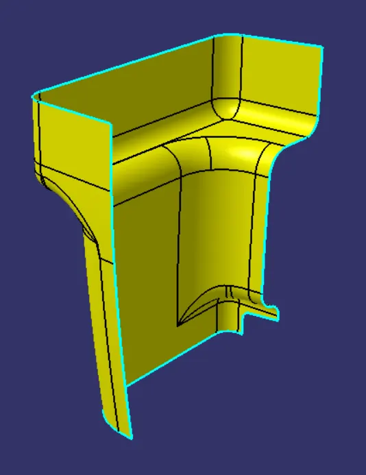
Tooling Axis:
It is defined as the direction in which the mould/core and cavity open. Selection of the direction of the tooling axis depends on the ease at which components can be easily ejected.
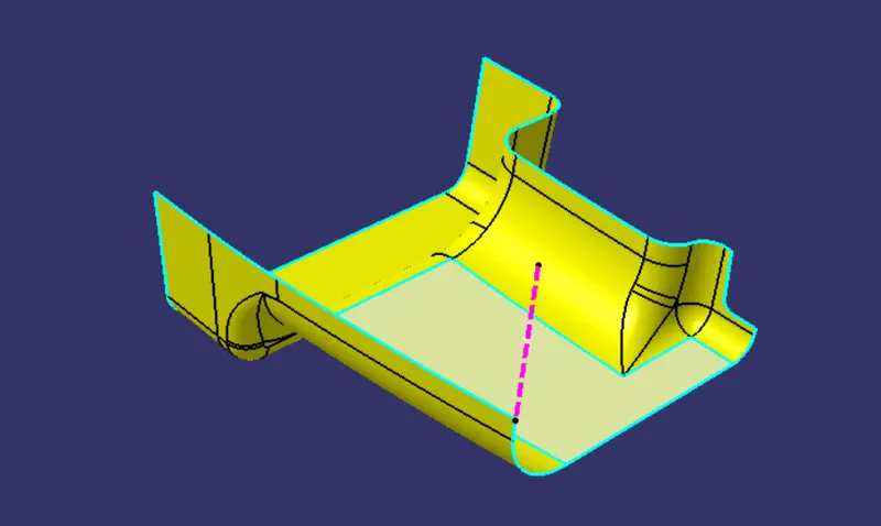
Draft Analysis:
Draft analysis is a method used in design to check whether the component created in CAD is manufacturable based on the draft condition applied. The main reason behind the draft analysis is the part manufactured should be easily removed from the mold. It also gives an idea of the draft angle from the tooling direction. The ideal draft angle given in automotive industries for plastic components is 3 degrees.
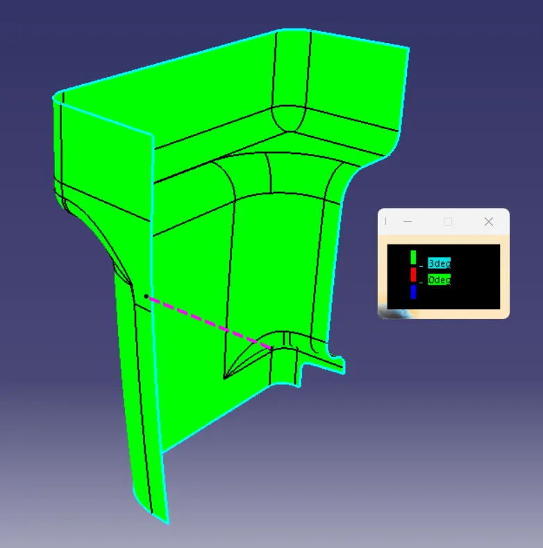
CREATING CLASS B SURFACE:-
- Extract the surfaces from the class A using multiple extract and untrim them.
- Use Extrapolate to make sure that all the untrims are properly intersected to trim and offset the surfaces to 2.5 mm to create the thickness.
- Fill the patches which are not offested by the using the commands like extract,boundary and multi-section surface.
- Then join the patches to the offseted surface using the command.So will get the complete class B.
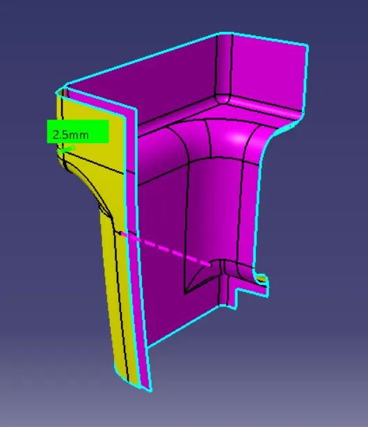
CREATING CLASS C SURFACE:-
For creating the class C surface once the B-class surface is created then form the A – Class surface the with the help of sweep command and with the tooling direction another surface is created intersecting the B Class surface created and then the surfaces are trimmed to get a single desired surface.
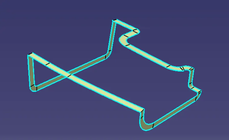
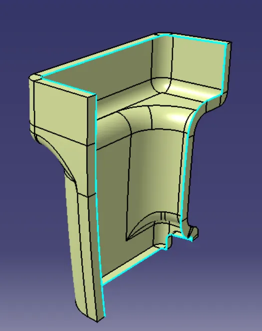
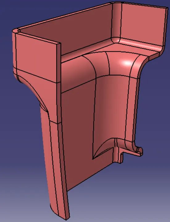
Final Join: Join with Class A and Class C Surface and Trim with Class B surface
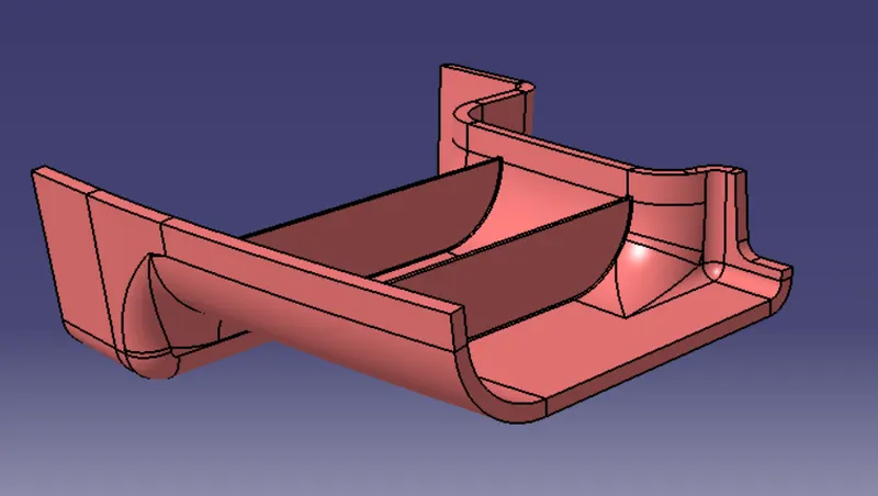
Creation of Ribs & Screw Boss:
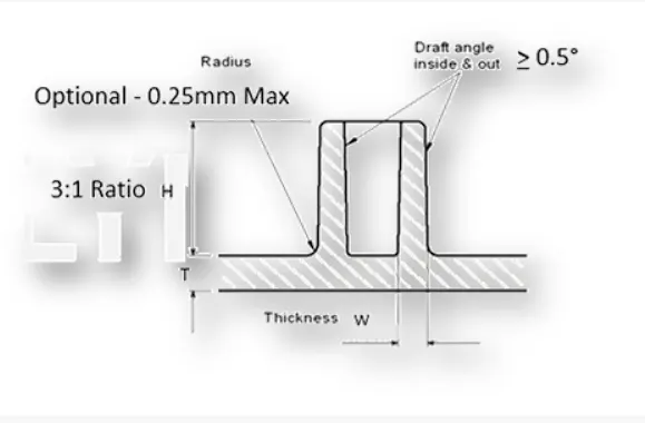
General Guidelines for Bosses:
- Draft - 0.5 degrees on the walls of boss
- Thickness - Typically 40%* of the nominal wall at the base.
- Height to Diameter Ratio - 3:1
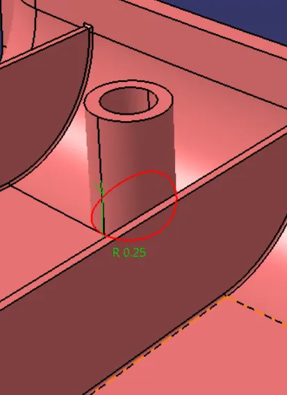
- Radii - 0.25mm maximum radii.
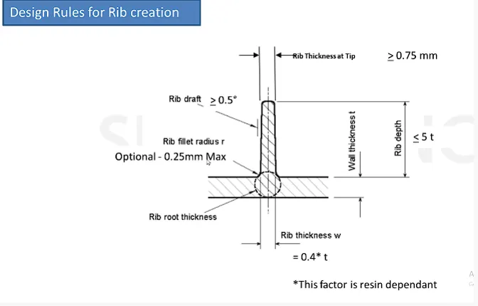
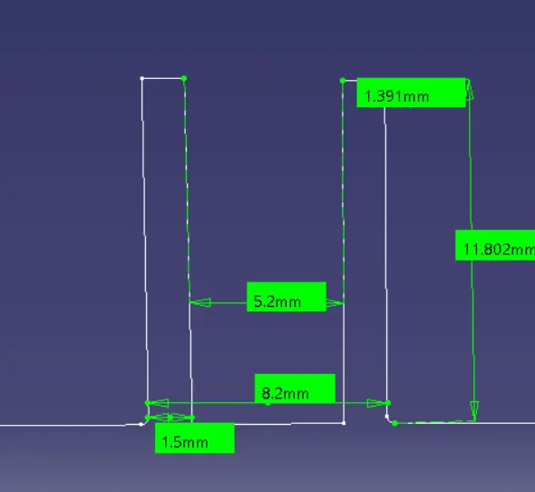
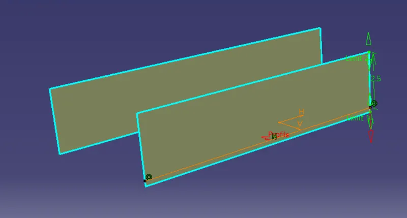
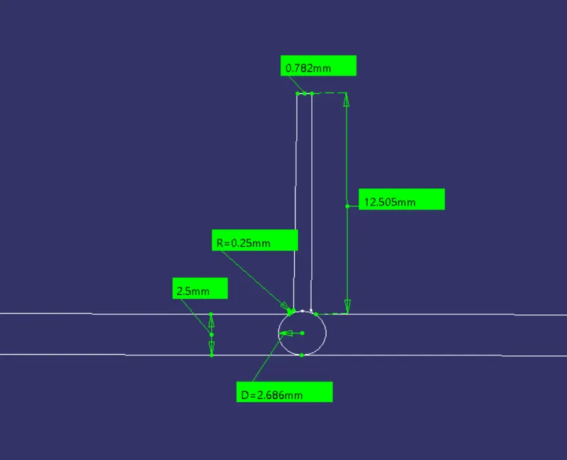
Next, the profile is extruded, to find the height,h=Wall thickness * 5
=2.5*5
= 12.5 mm
Therefore, the height is 12.5 mm
The extruded surface is thickened,
Thickness,w=0.4*t
=0.4 2.5
=1mm
Therefore, the thickness of the rib is 1 mm
General Guidelines for Bosses:
- Draft - 0.5 degrees on the walls of boss
- Thickness - Typically 40%* of the nominal wall at the base.
- Height to Diameter Ratio - 3:1
- Radii - 0.25mm maximum radii.