Week 12- Final project
|
Development of a Door Trim panel |
Aim:-
Creation of CAD model considering the following inputs as like in OEM and tier1 companies
- Class A surface
- Nominal thickness: Refer to master sections
- Attachment strategy :
Find an attachment strategy for the door panel complete work.
Use Push pin with Dog house for Lower substrate – Door panel attachment
Use heat stakes for part-to-part attachment
INTRODUCTION:
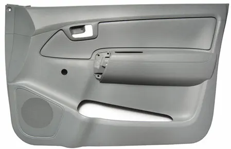
The door panel is the interface between the car's interior and the door's inner workings. Generally, the door panel is divided into parts for easy designing like the armrest, map pocket, and the lower substrate. This requires one of the toughest requirements among the car's interior parts. This should be designed to withstand a load less than 2mm in thickness and protect the occupants during collisions.
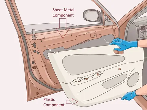
The door currently has an inner full-width panel consisting of electronic windows, a central locking system, and speakers. These panels typically consist of a foamed core covered with either textiles or plastics.
METHODOLOGY:
The first thing is to check what inputs are given to us and then try to make the parts of the given input work on it step by step
so here we divided the given input into five-part also for the B-side features push-pins are given
1. Master sections
2. Door Arm Rest
3. Lower Substrate
4. Outer Map Pocket
5. Inner Map Pocket
~~~~~~~~~~~~~~~~~~~~~~~~~~~~~~~~~~~~~~~~~~~~~~~~~~~~~~~~~~~~~~~~~~~~~~~~~~~~~~~~~~~~~~~~~~~~~~~~~~~~~~~~~~~~~~
Now creating the Door Arm Rest
Class A
Now check the given class a if it is ok then go ahead with the further steps
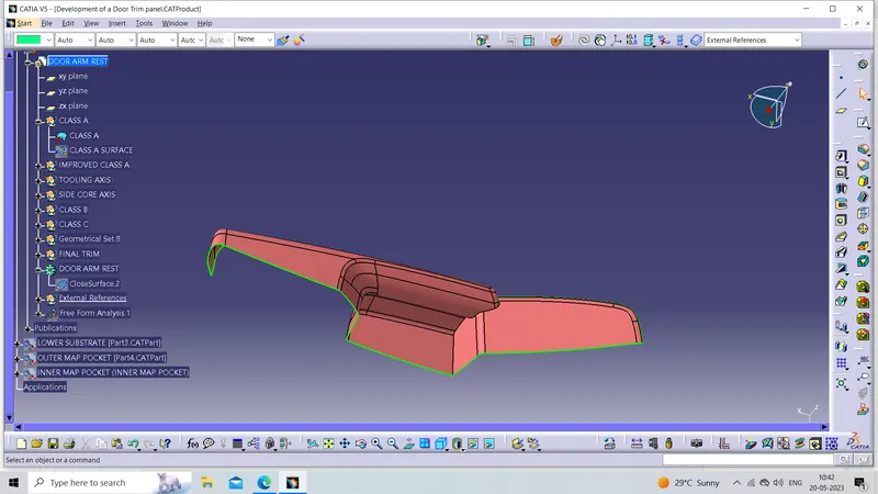
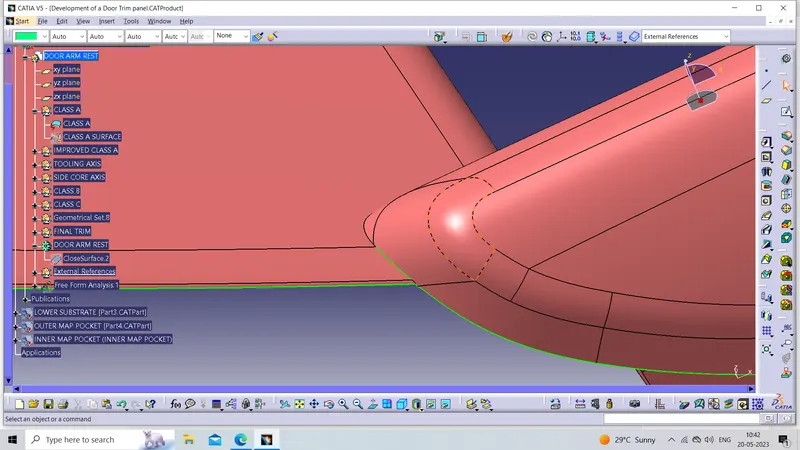
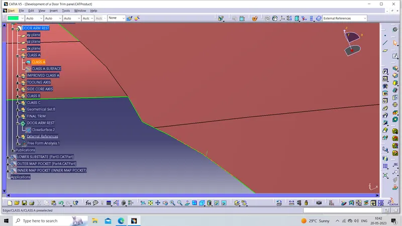
Tree Structure for Class A
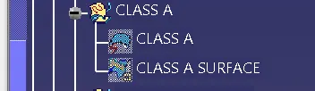
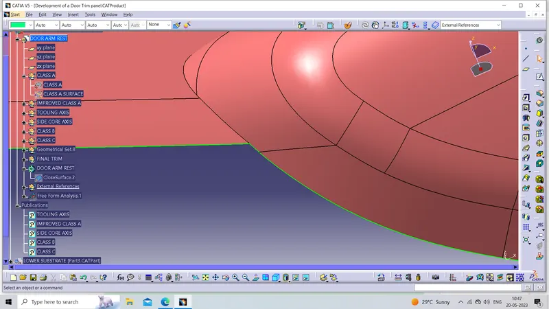
but the given class has some defects (like some parts are not joined properly And some sharp edges are coming outside these will affect our class b surface)so we have to resolve the defect and then we go for the next step
Improved class A
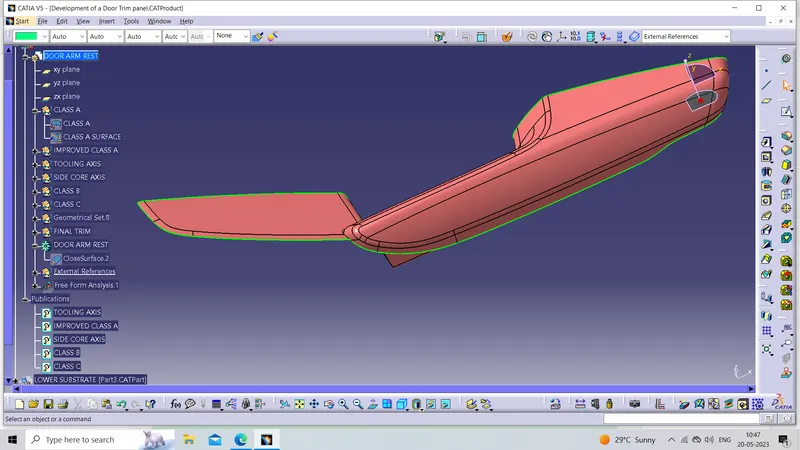
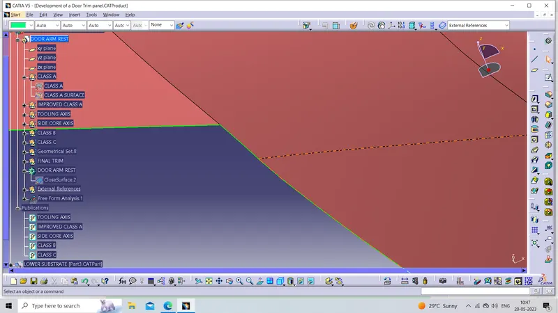
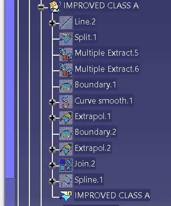
Tree Structure for Improved Class A
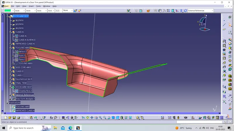
Now creating Tooling Axis
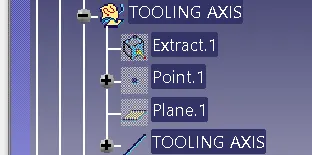
Tree Structure for Tooling Axis
Creating side core axis
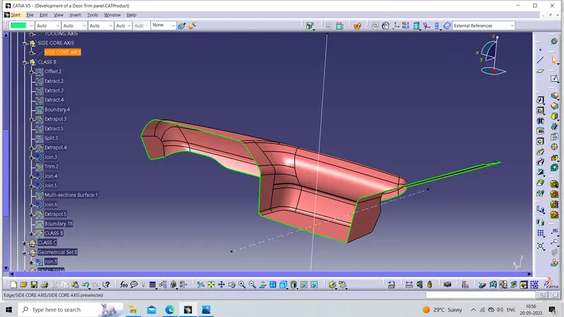
Tree Structure for Side Core Axis

Creating Class B
Now creating Class B by offsetting the improved Class A by using the offset command shown below picture
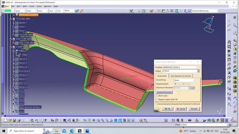
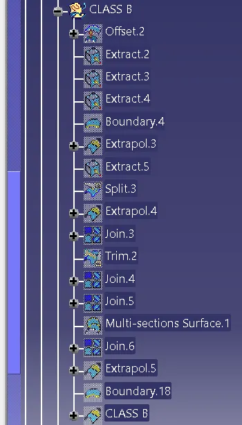
Tree Structure for Class B
Now Creating Class C
Now Creating Class C using the sweep command on the Improved Class A
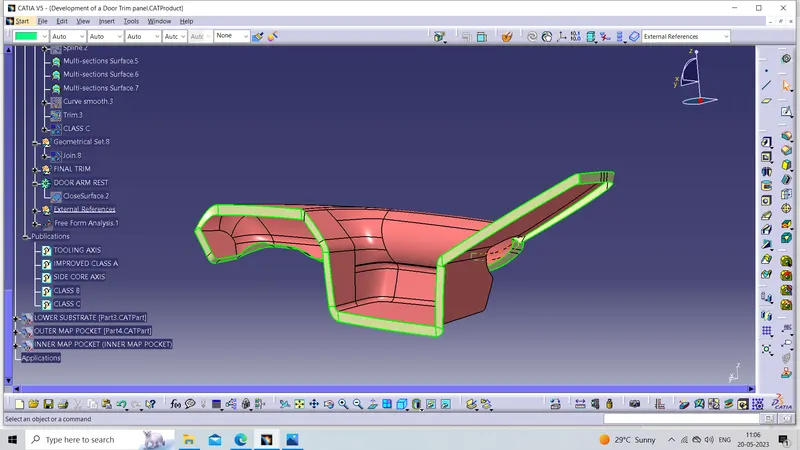
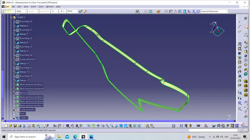
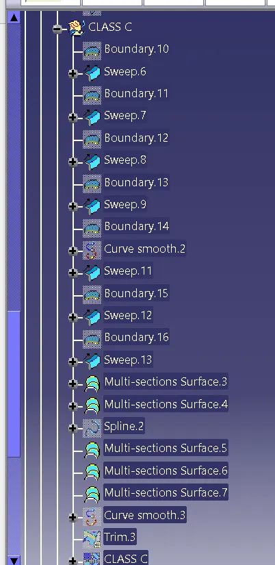
Tree Structure for Class C
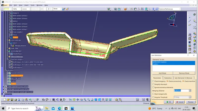
Now join Improved Class A & Class C together
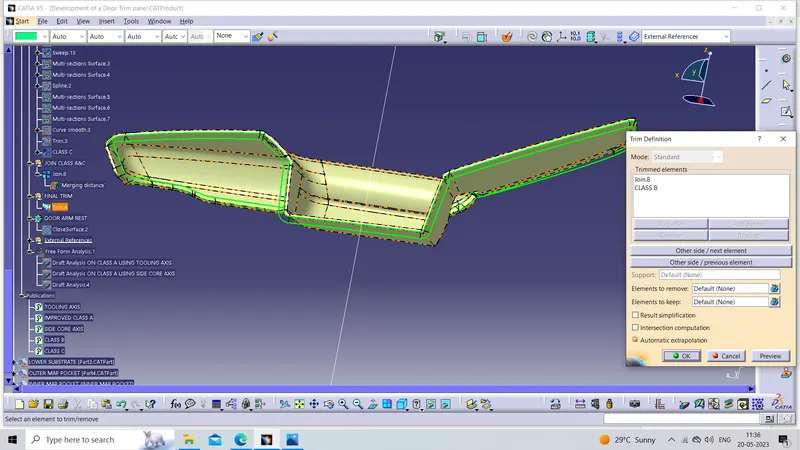
Now Triming Above join with Class B For getting a closed body
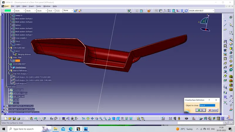
Now use the close surface command to make our close surface body solid
Draft Analysis
At Improved Class A side of solid body
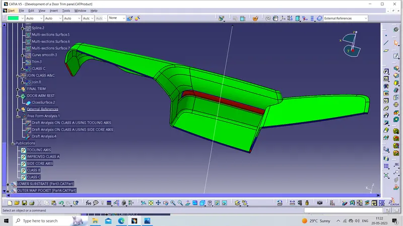
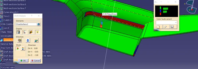
All the area with a minimum draft of 3 degrees expects the areas shown in the next picture
The Minimum value in this area is -7.057degree
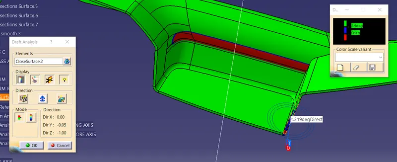
The Minimum value in this area is 1.319 degree
A Class B side of a solid body
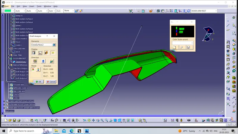
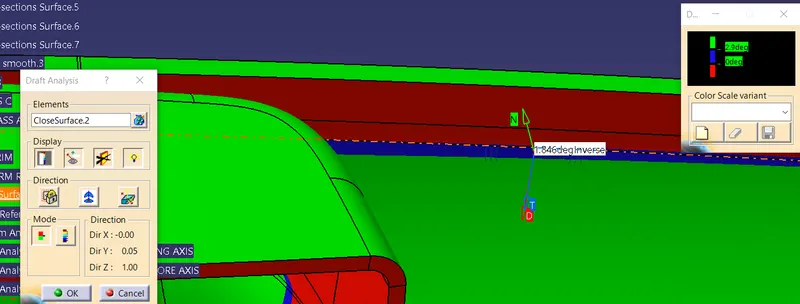
All the area with a minimum draft of 3 degrees expects the areas shown in the next picture
The Minimum value in this area is 1.846degree
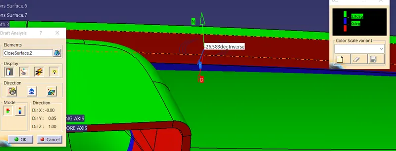
The Minimum value in this area is -26.583degree
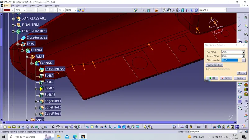
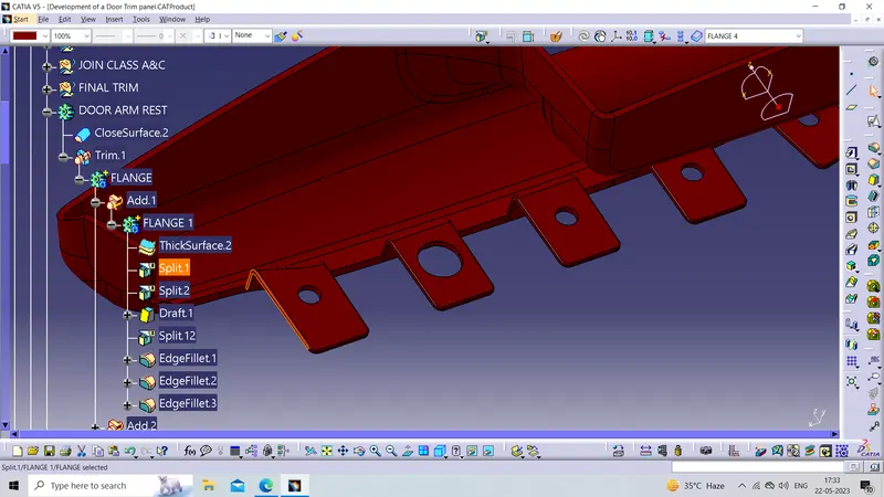
Now creating the FLANGES on the DOOR ARM REST by using the Given Master sections
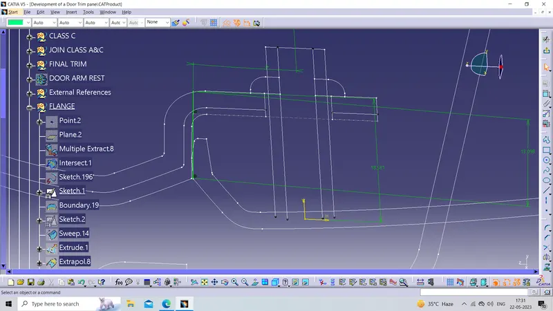
The above picture shows how the profile of FLANGE which is created with the help p of the Given master section No go to generative shape design workbench And by using sweep and the extrude command we create the surface profile body and then go to the part workbench and use the thick surface command to make the solid body from the surface profile which is shown below and then split them As per desired dimensions
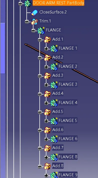
The tree structure of the DOOR ARM REST PartBody
ISOMETRIC VIEW
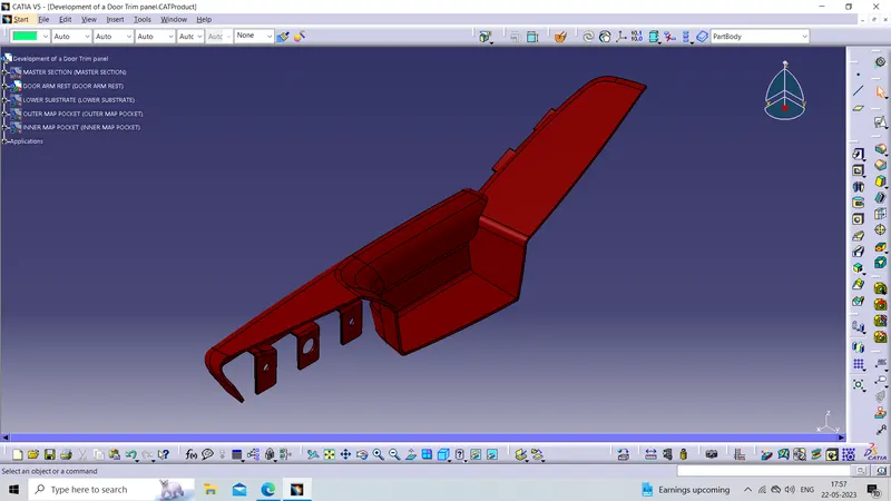
FRONT VIEW
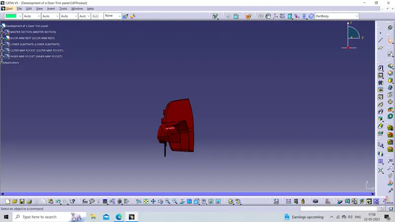
SIDE VIEW
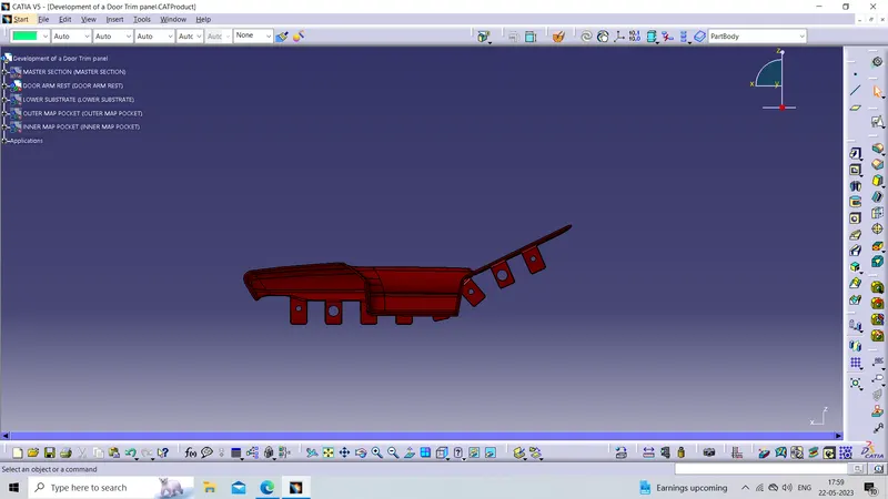
TOP VIEW
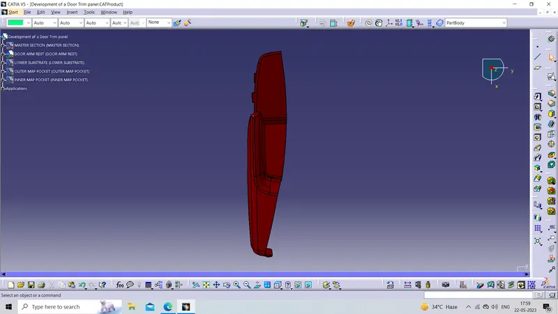
~~~~~~~~~~~~~~~~~~~~~~~~~~~~~~~~~~~~~~~~~~~~~~~~~~~~~~~~~~~~~~~~~~~~~~~~~~~~~~~~~~~~~~~~~~~~~~~~~~~~~~~~~~~~~~
Now creating the Lower Substrate
Class A
Now check the given class if it is ok then Improved it then use it
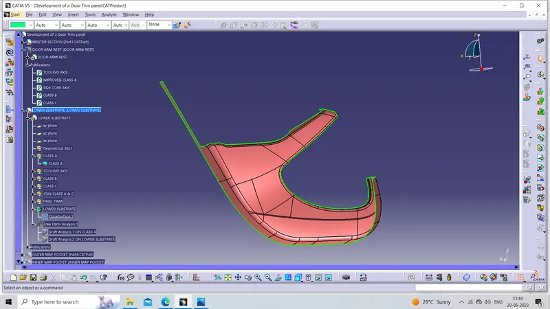
Tree Structure for Class A

Now creating Tooling Axis
To create the tooling axis first, we have to check the best suitable direction for tooling by using the compass. the y direction is suitable for creating the tolling axis because, in the y direction, most of the surfaces are clearing while performing draft analysis. Generally tooling axis is created using bisecting line method but here A line normal to the surface is created in the y direction and considered the tooling axis.
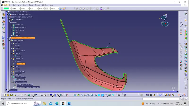
Tree Structure for Tooling Axis

Creating Class B
Now creating Class B by offsetting Class A by using the offset command shown below picture
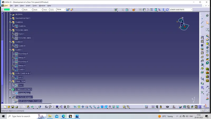
Tree Structure for Class B

Now Creating Class C
Now Creating Class C using the sweep command on Class A
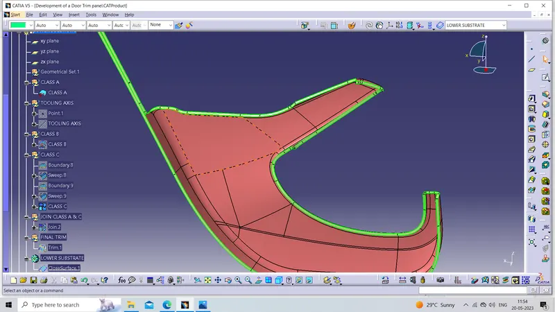
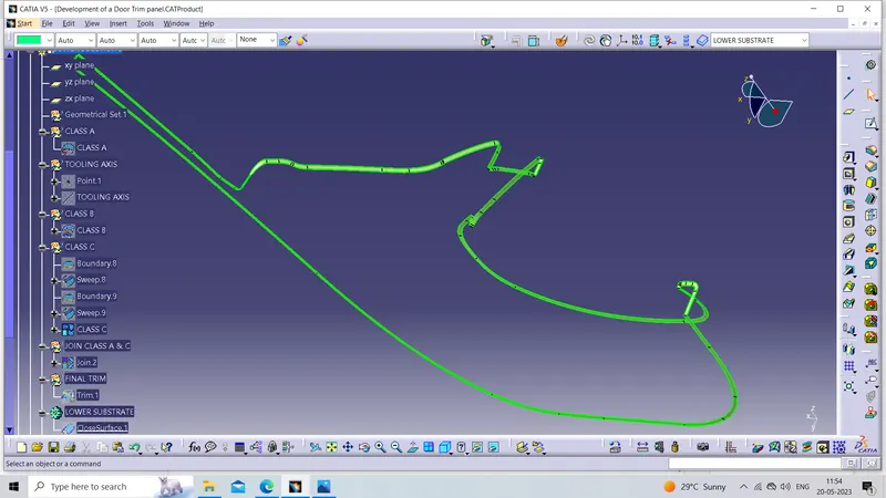
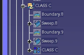
Tree Structure for Class C
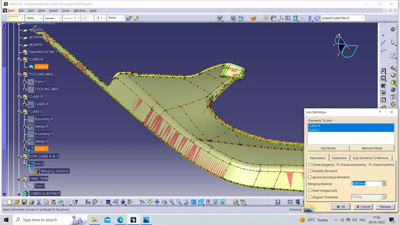
Now join Class A & Class C together
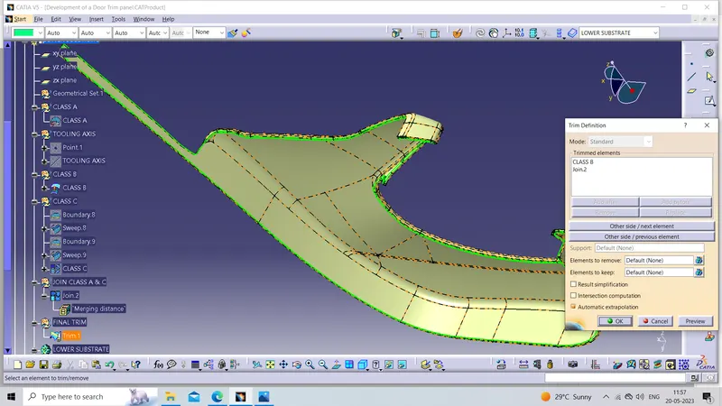
Now Triming Above join with Class B For getting a closed body
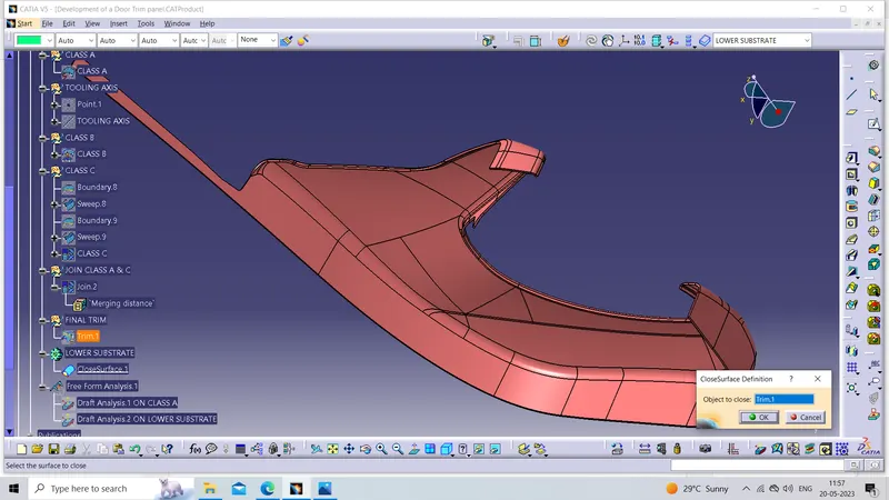
Now use the close surface command to make our close surface body solid
Draft Analysis
At Class A side of solid body
All the area with a minimum draft of 3 degrees expects the areas shown in the next picture
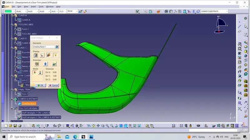
At the Class B side of a solid body
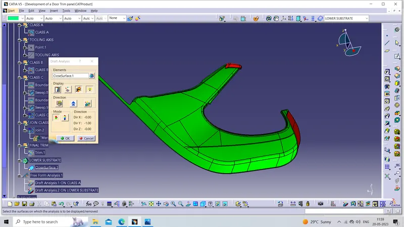
All the area with a minimum draft of 3 degrees expects the areas shown in the next picture
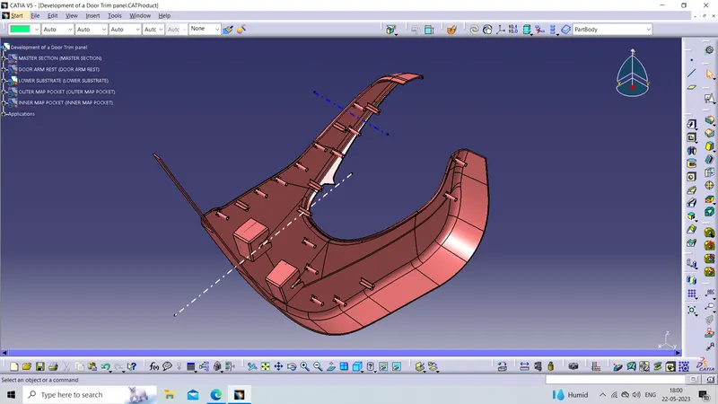
As we observe the lower substrate is the main part on which other parts are attached with the help of HEAT STAKES, and LOCATORS, now we are creating HEAT STAKES, LOCATORS, and DOG HOUSE on the lower substrate
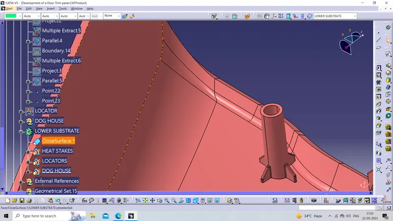
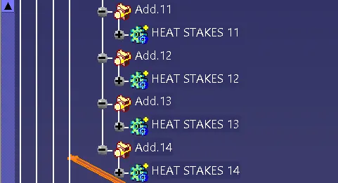
Creation of Heat stake
Heat stakes are used in thermoplastics to assemble two parts by locally heating and cooling the plastic material and allowing it to reform itself and act as a joint for the two materials.
We have placed 9 heat stakes in the model based on the reference points created by estimation.
One of the important factors to be considered while designing the heat skates is the height of the heat skates. It should always be less than the height of the locators.
Sketch of HEAT STAKES
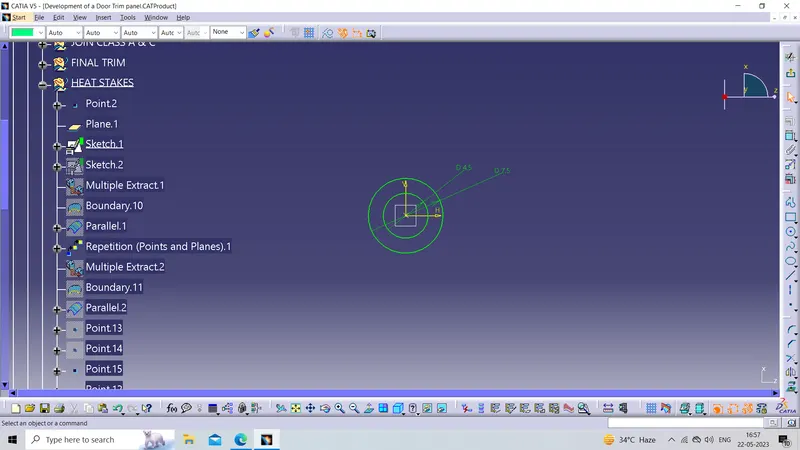
RIBS for Heat stakes
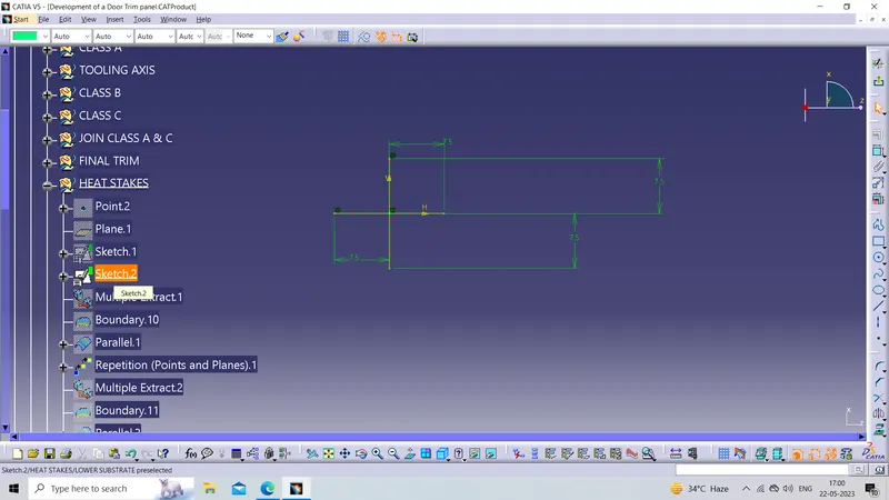
Now pad it
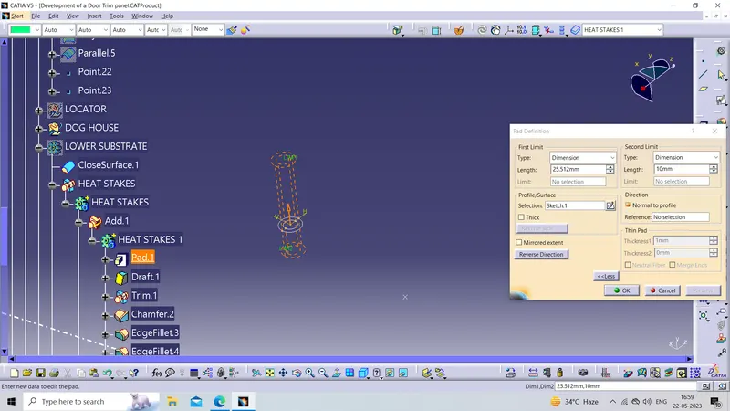
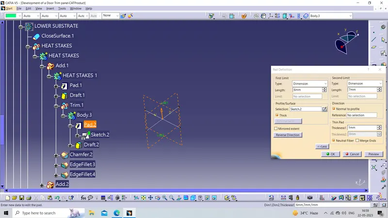
Now give the proper draft Fullet chamfer to the HEAT STAKES And RIBS as per the OEM standards then unitrim HEAT STAKES with RIBS And remove faces RIBS inside the HEAT STAKES then unitrim from the main body
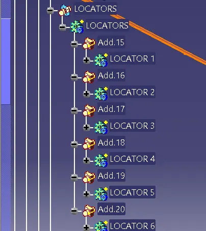
Now creating the LOCATORS
The main purpose of locators is to facilitate the proper locking of two components together while assembling and arresting the maximum degrees of freedom possible.
These locators are similar to guide pins provided in mold.
The two types of locators used are two-way locators and four-way locators.
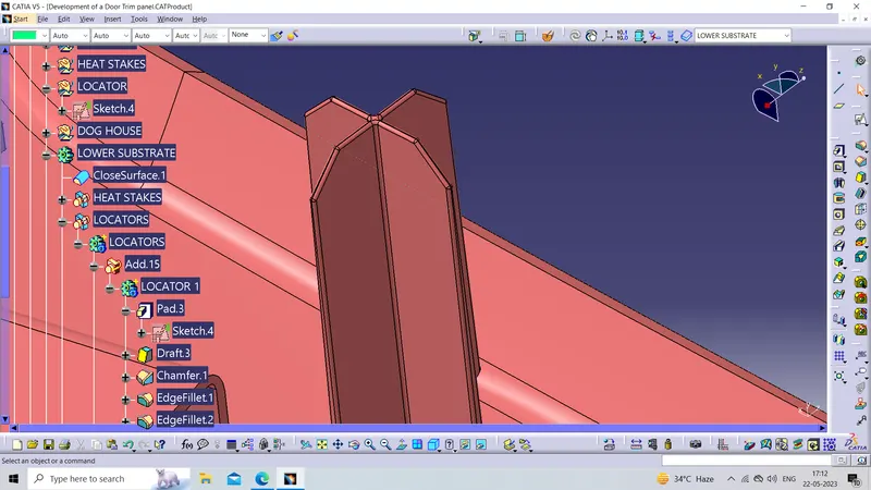
We have positioned three 4 way locators in our model which meet the rib design criteria.
sketch
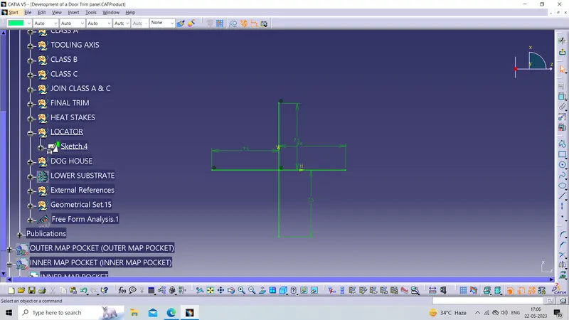
Now pad it
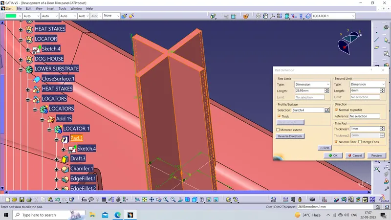
Now give the proper draft Fullet chamfer to the LOCATOR as per the OEM standards then unitrim LOCATORS from the main body
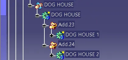
Now creating the DOG HOUSE
The two main purposes of a dog house are to avoid sink marks and to house various other engineering features like screw bosses, locators, push clips, etc.
In this case, the dog house is designed to house the push clips and the 4-way locator. The dog house designed for the push clip features a slot on the top face to accommodate the push clip
The dog house should follow certain design rules which are stated below
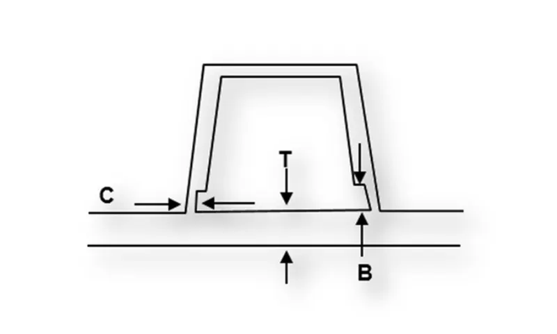
Doghouse wall thickness at the intersection of the part wall (C) should be 40% or less than the main wall stock (T).
The height of ( B ) should be between 3.0 – 6.0 mm
The outer surface of the dog house must have a draft angle of 3 degrees
The inner surface of the dog house must have a draft angle of 0.5 degrees
Sketch
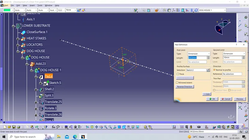
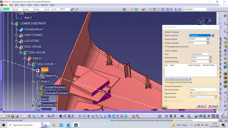
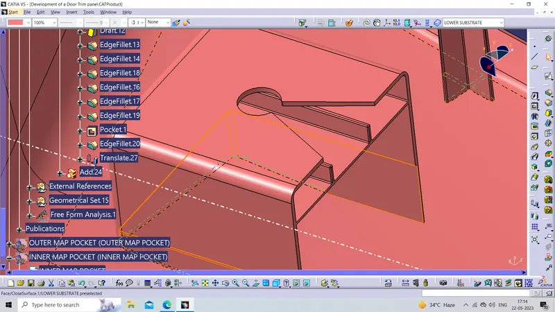
Now copy the Above B-side features And paste special then use the translation command to place the B-side features at the desired location And then trim them from the main body by using the unitrim command
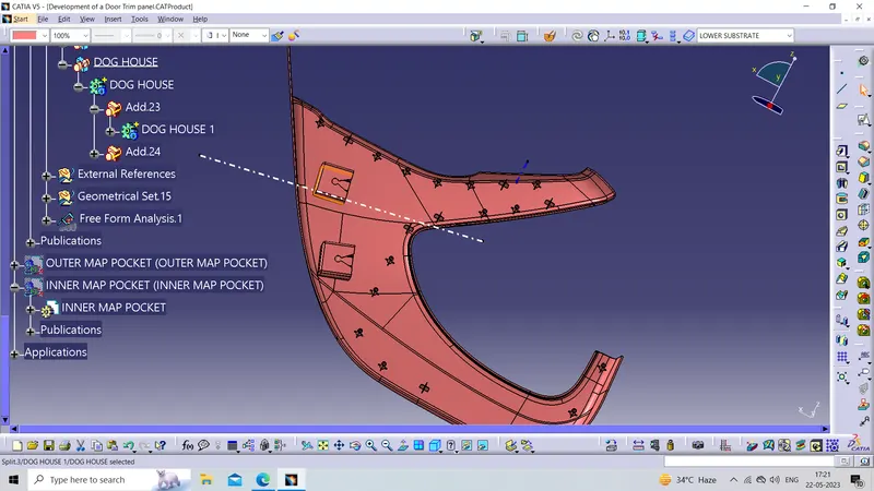
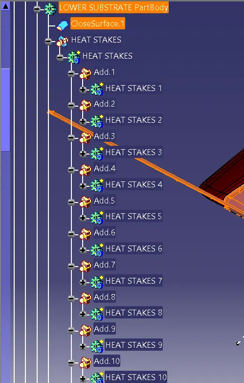
The tree structure of the LOWER SUBSTRATE PartBody
ISOMETRIC VIEW
FRONT VIEW
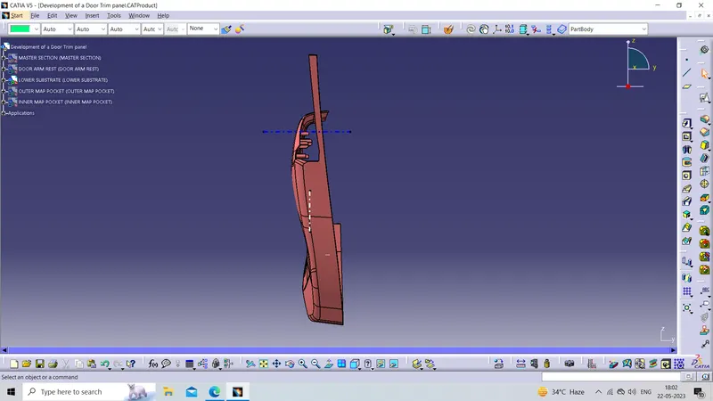
SIDE VIEW
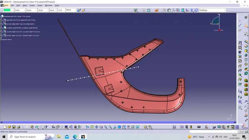
TOP VIEW
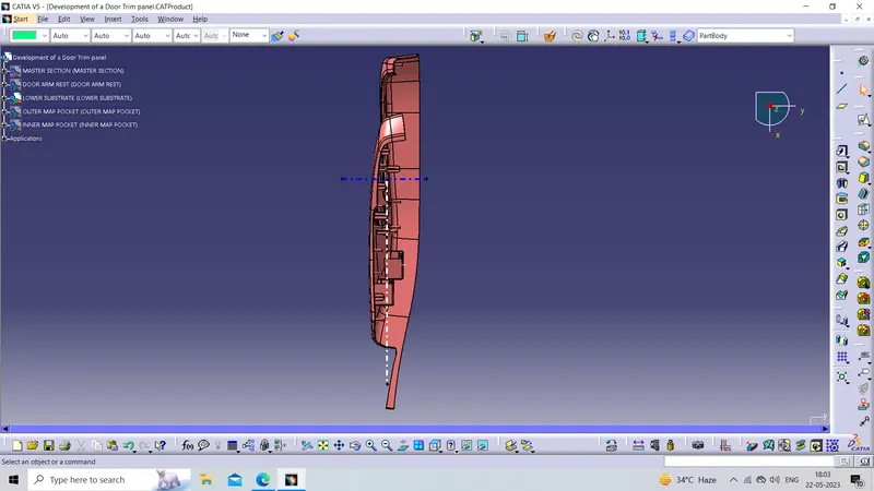
~~~~~~~~~~~~~~~~~~~~~~~~~~~~~~~~~~~~~~~~~~~~~~~~~~~~~~~~~~~~~~~~~~~~~~~~~~~~~~~~~~~~~~~~~~~~~~~~~~~~~~~~~~~~~~
Now creating the Outer Map Pocket
Class A
Now check the given class if it is ok then Improved it then use it
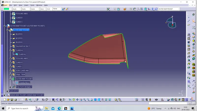
Tree Structure for Class A

Now creating Tooling Axis
To create the tooling axis first, we have to check the best suitable direction for tooling by using the compass. the y direction is suitable for creating the tolling axis because, in the y direction, most of the surfaces are clearing while performing draft analysis. Generally tooling axis is created using bisecting line method but here A line normal to the surface is created in the y direction and considered the tooling axis.
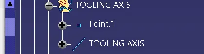
Tree Structure for Tooling Axis
Creating Class B
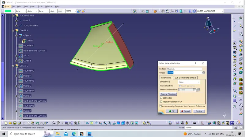
Now creating Class B by offsetting the improved Class A by using the offset command shown below picture
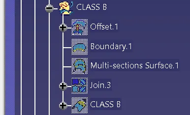
Tree Structure for Class B
Now Creating Class C
Now Creating Class C using the sweep command on the Improved Class A
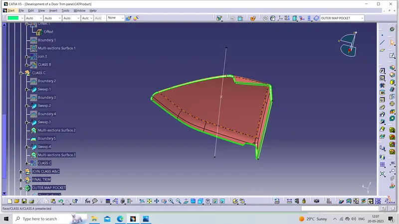
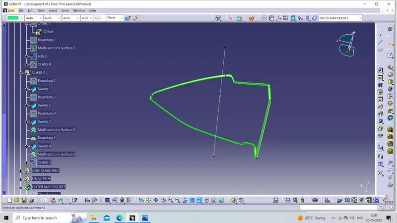
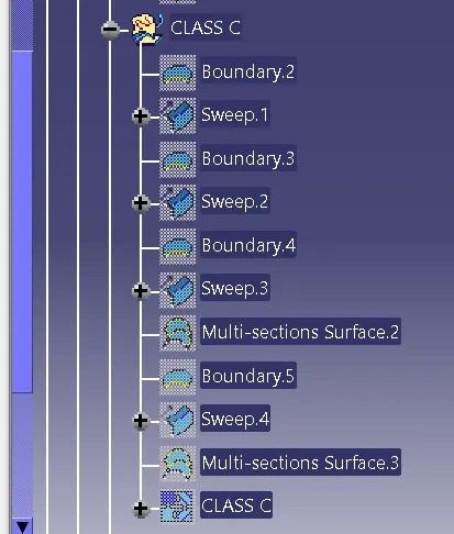
Tree Structure for Class C
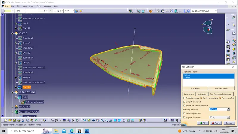
Now join Class A & Class C together
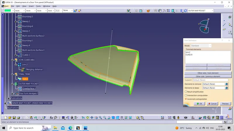
Now Triming Above join with Class B For getting a closed body
Now use the close surface command to make our close surface body solid
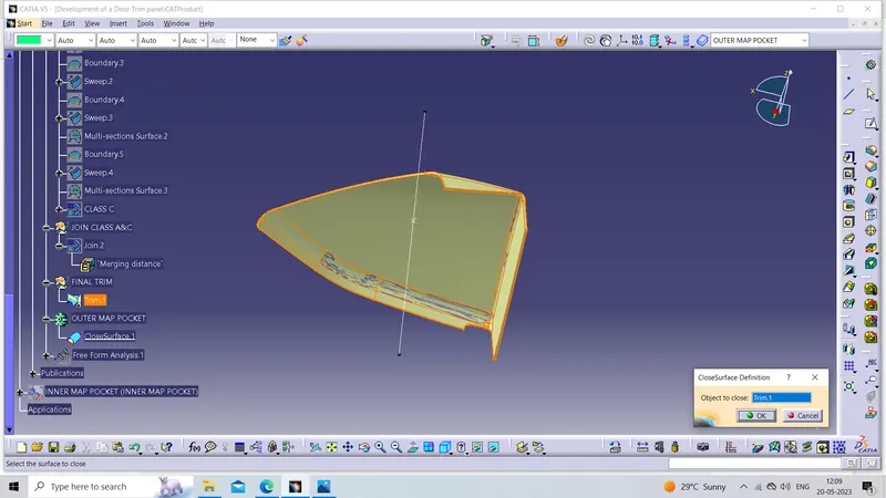
Draft Analysis
At Class A side of solid body
All the area with a minimum draft of 3 degrees expects the areas shown in the next picture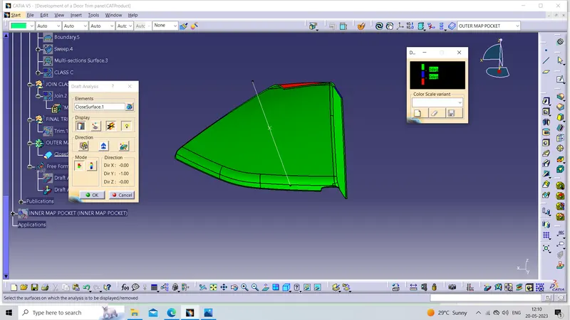
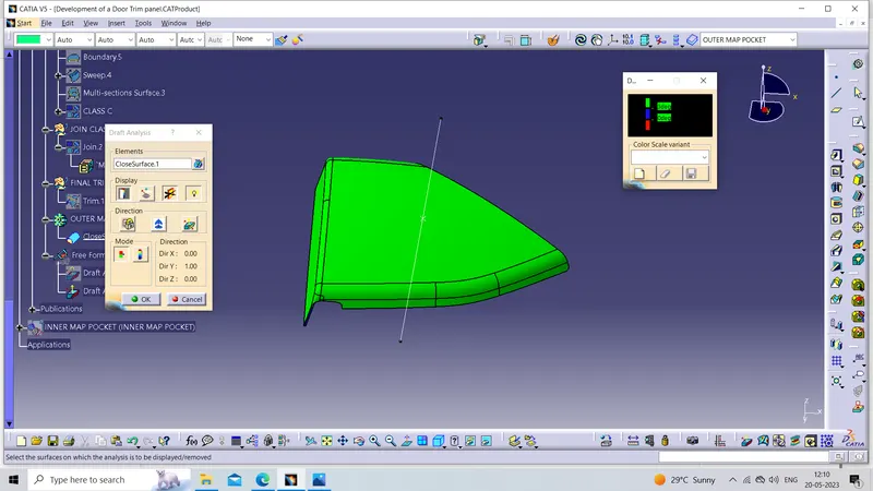
A Class B side of a solid body
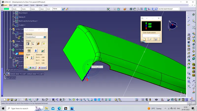
All the area with a minimum draft of 3 degrees expects the areas shown in the next picture
The Minimum value in this area is 0.418degree
Now creating the FLANGES on the INNER MAP POCKET by using the Given Master sections
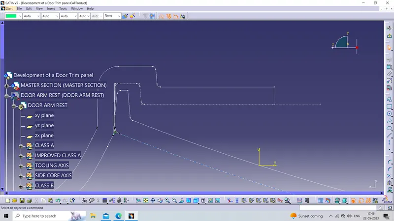
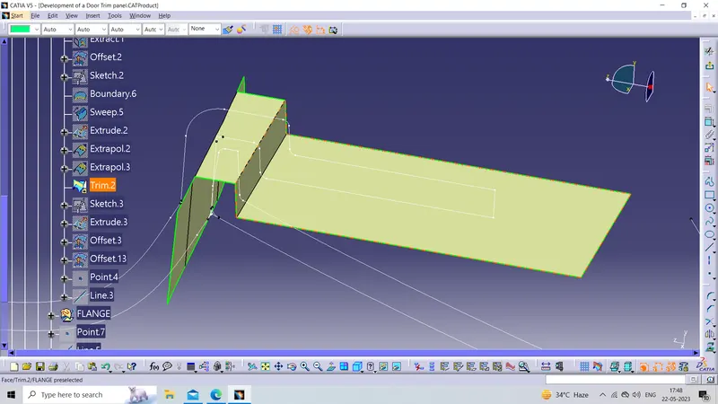
The above picture shows how the profile of FLANGE which is created with the help p of the Given master section No go to generative shape design workbench And by using sweep and the extrude command we create the surface profile body and then go to the part workbench and use the thick surface command to make the solid body from the surface profile which is shown below and then split them As per desired dimensions
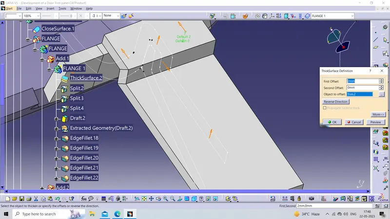
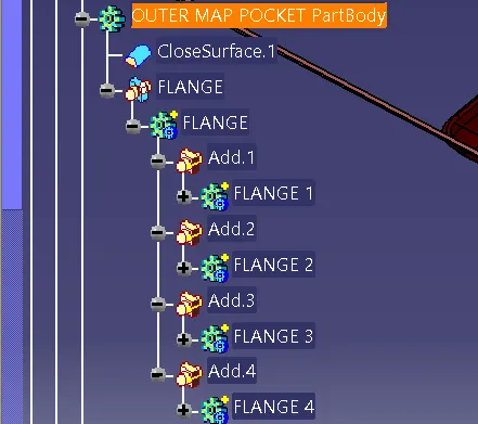
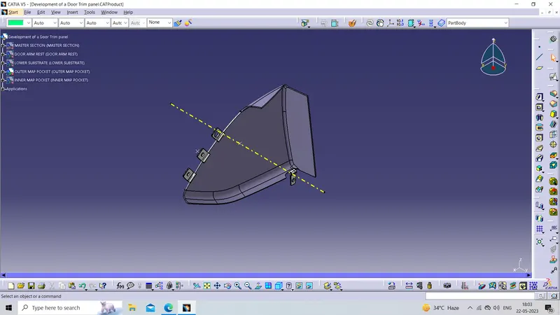
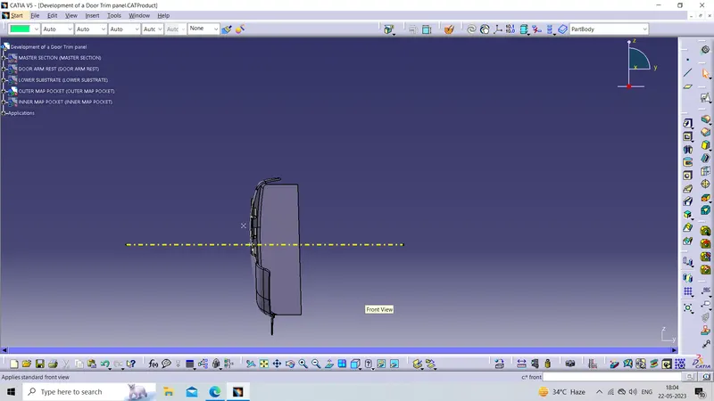
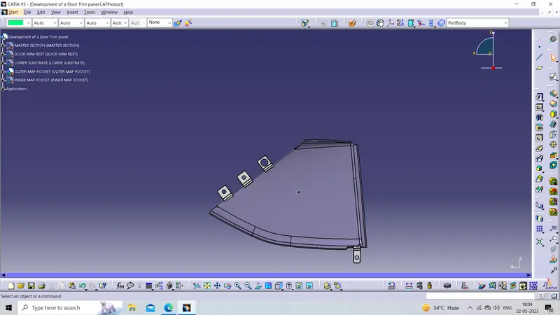
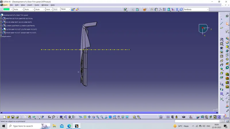
The tree structure of the inner OUTER Map Pocket PartBody
ISOMETRIC VIEW
FRONT VIEW
SIDE VIEW
TOP VIEW
~~~~~~~~~~~~~~~~~~~~~~~~~~~~~~~~~~~~~~~~~~~~~~~~~~~~~~~~~~~~~~~~~~~~~~~~~~~~~~~~~~~~~~~~~~~~~~~~~~~~~~~~~~~~~~
Now creating the inner Map Pocket
Class A
Now check the given class if it is ok then Improved it then use it
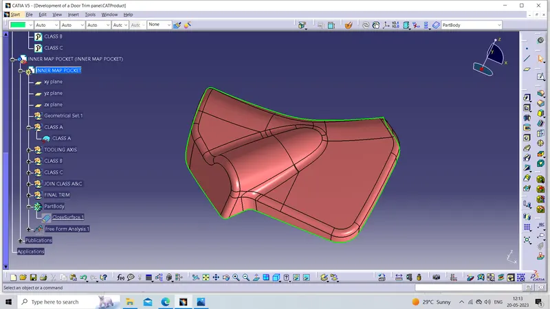
Tree Structure for Class A

Now creating Tooling Axis
To create the tooling axis first, we have to check the best suitable direction for tooling by using the compass. the y direction is suitable for creating the tolling axis because, in the y direction, most of the surfaces are clearing while performing draft analysis. Generally tooling axis is created using bisecting line method but here A line normal to the surface is created in the y direction and considered the tooling axis.
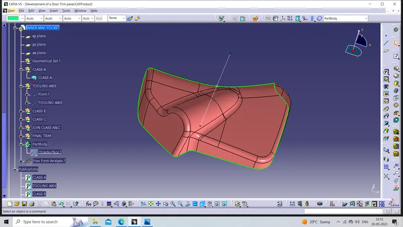
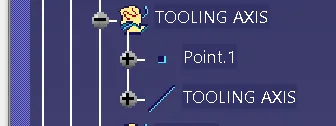
Tree Structure for Tooling Axis
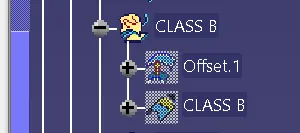
Creating Class B
Now creating Class B by offsetting the improved Class A by using the offset command shown below picture
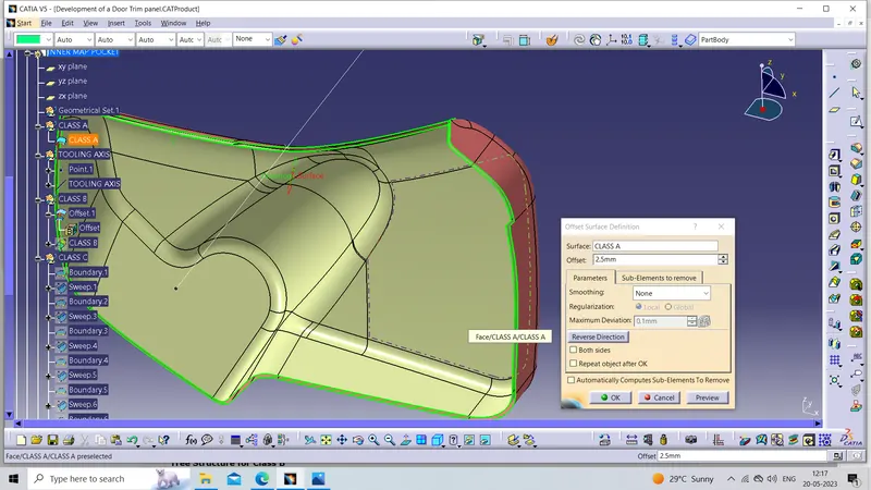
Tree Structure for Class B
Now Creating Class C
Now Creating Class C using the sweep command on the Improved Class A
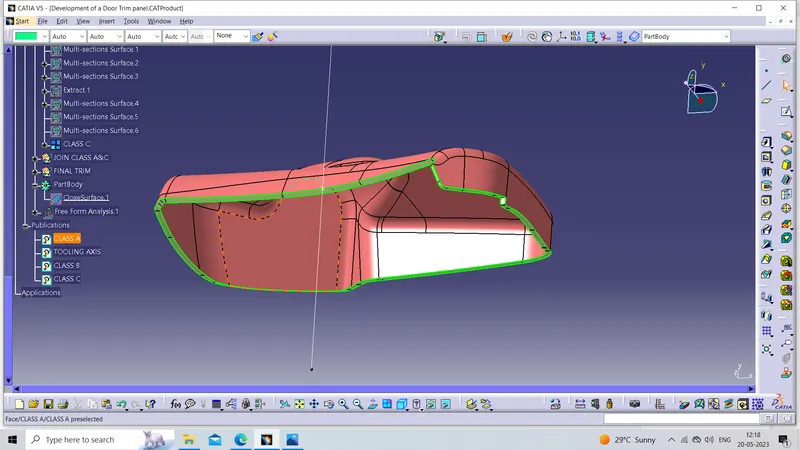
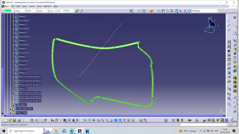
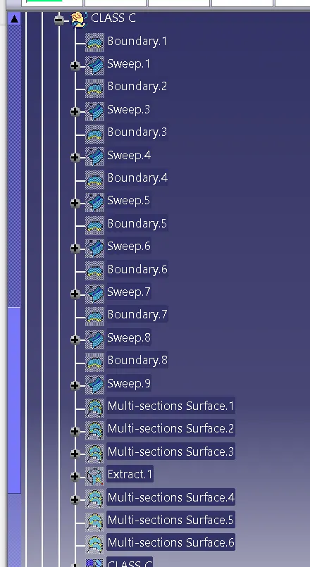
Tree Structure for Class C
Now join Class A & Class C together
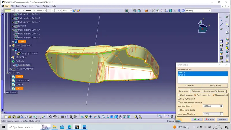
Now Triming Above join with Class B For getting a closed body
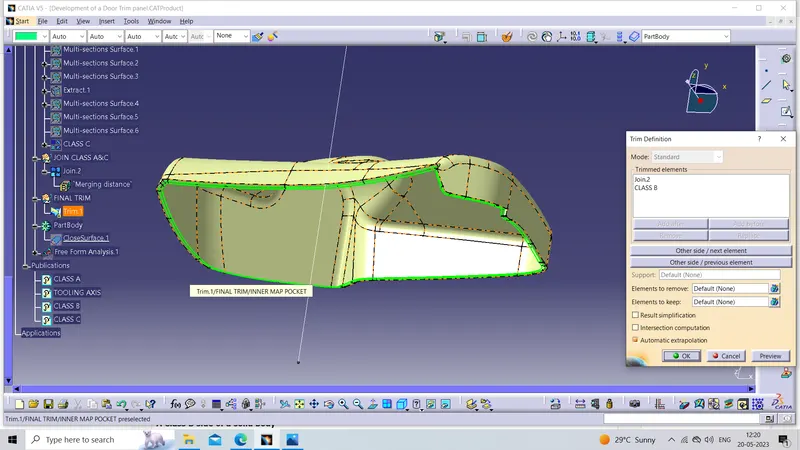
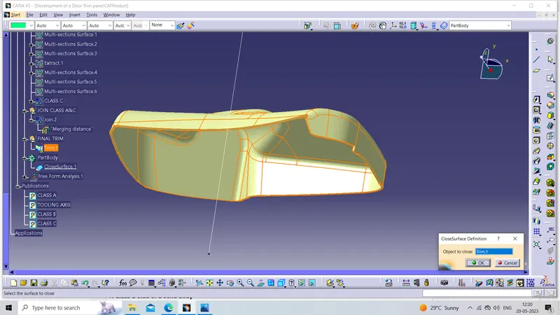
Now use the close surface command to make our close surface body solid
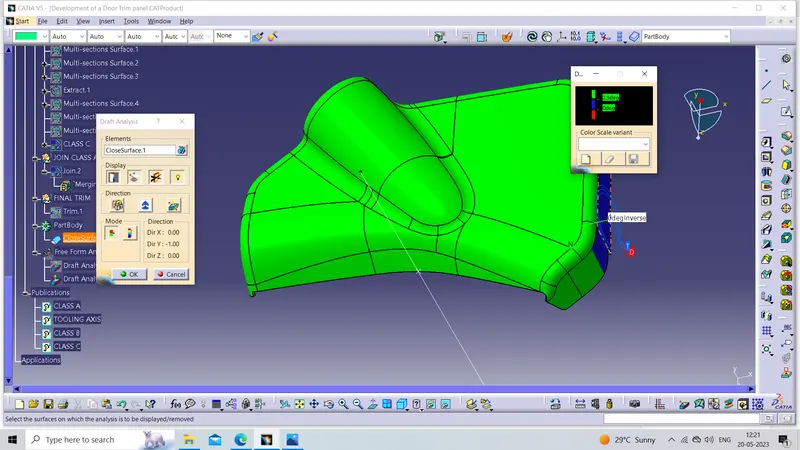
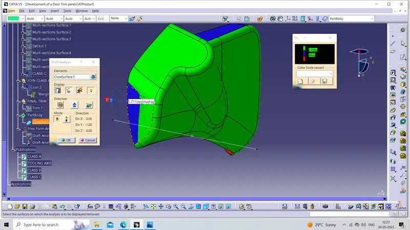
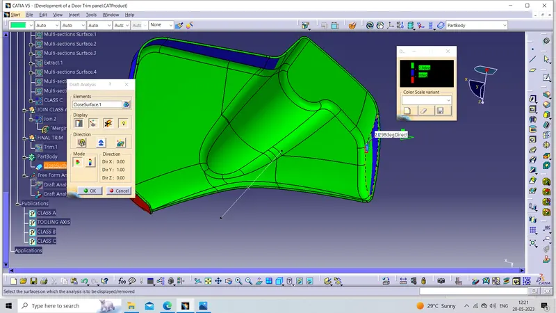
Draft Analysis
At Class A side of solid body
All the area with a minimum draft of 3 degrees expects the areas shown in the next picture
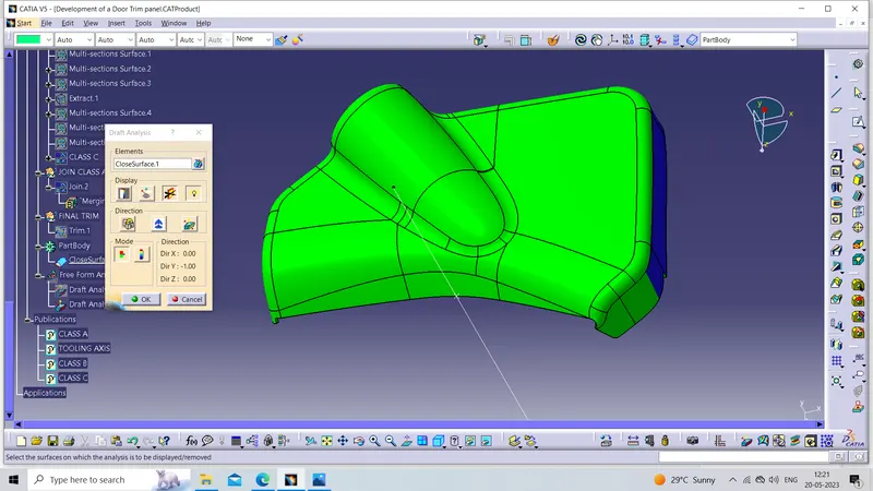
The Minimum value in this area is -7.057degree
The Minimum value in this area is 1.319 degree
At the Class B side of a solid body
All the area with a minimum draft of 3 degrees expects the areas shown in the next picture
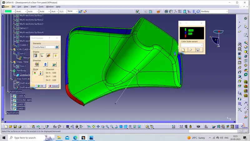
The Minimum value in this area is 0 degree
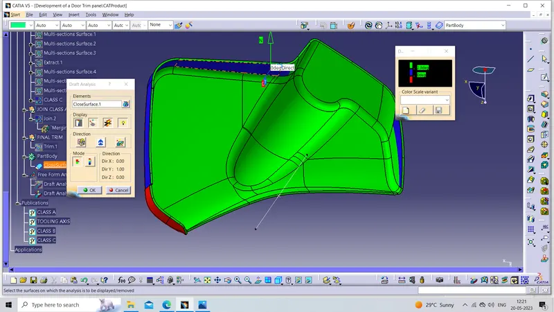
The Minimum value in this area is 2.298degree
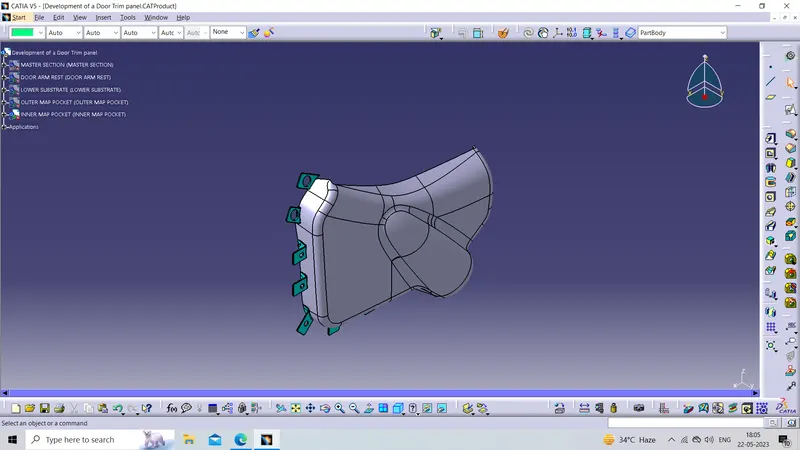
Now creating the FLANGES on the OUTER MAP POCKET by using the Given Master sections
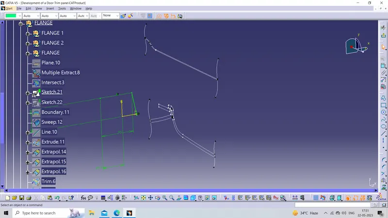
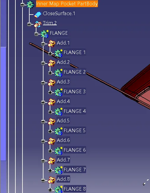
The above picture shows how the profile of FLANGE which is created with the help p of the Given master section No go to generative shape design workbench And by using sweep and the extrude command we create the surface profile body and then go to the part workbench and use the thick surface command to make the solid body from the surface profile which is shown below and then split them As per desired dimensions
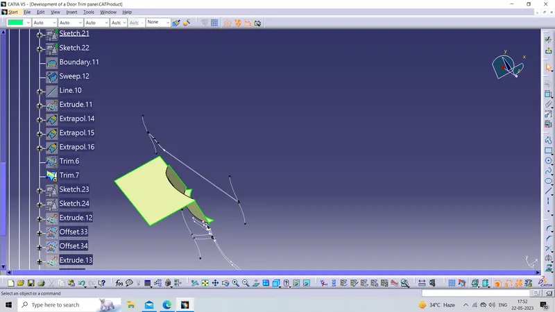
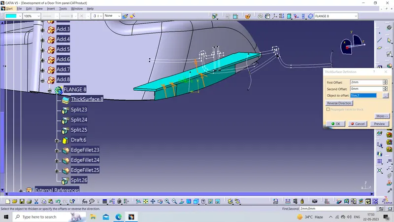
The tree structure of the inner Inner Map Pocket PartBody
ISOMETRIC VIEW
FRONT VIEW
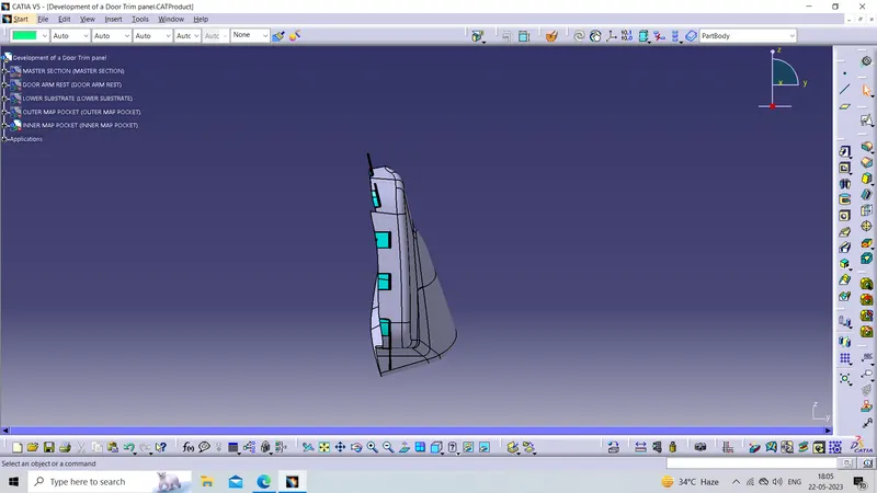
SIDE VIEW
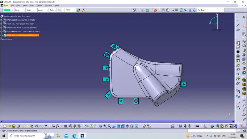
TOP VIEW
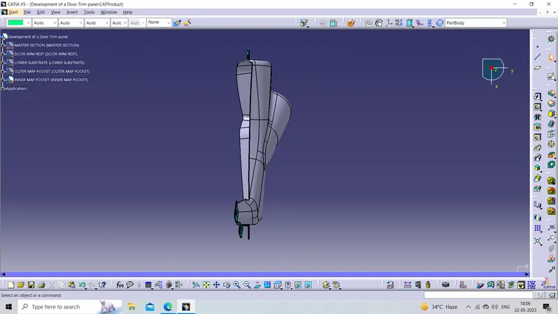
~~~~~~~~~~~~~~~~~~~~~~~~~~~~~~~~~~~~~~~~~~~~~~~~~~~~~~~~~~~~~~~~~~~~~~~~~~~~~~~~~~~~~~~~~~~~~~~~~~~~~~~~~~~~~~
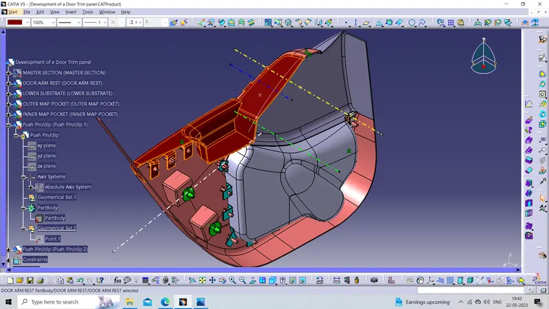
Now we have to fix the all above components in Assembly Work Bench by using the Fix Component Command
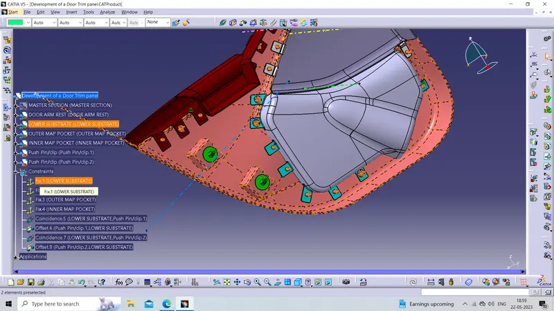
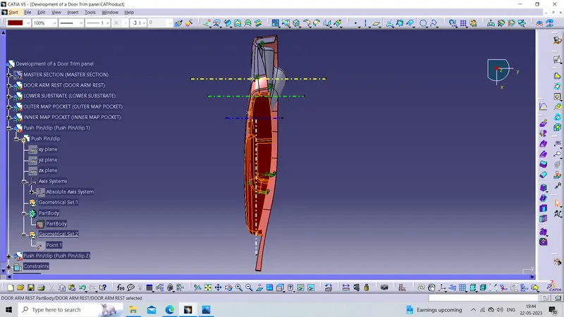
Then we have to Place the Given Push pin on the top of DOG HOUSE by using the Different constraint commands Shown in the below picture
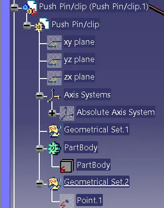
TREE STRUCTURE OF PUSH PIN
click on coincidence constraint then Select the Axis of DOG HOUSE And Push Pin
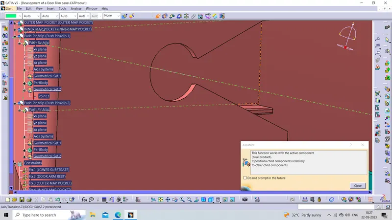
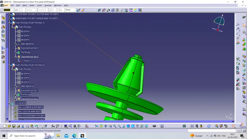
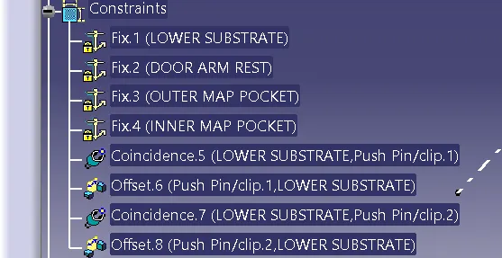
Then use the offset constraint command
Select the faces which are going to mate with each other
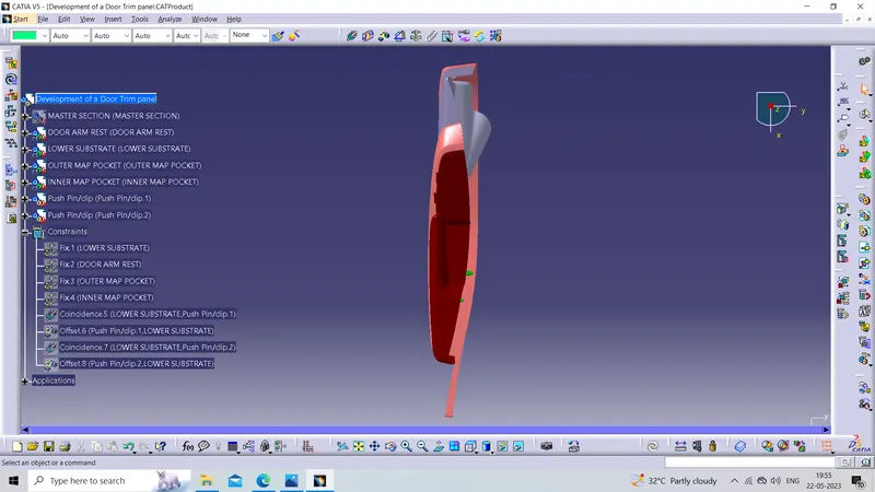
The tree structure of constraints
FINAL ASSEMBLY Door Trim Panel
ISOMETRIC VIEW
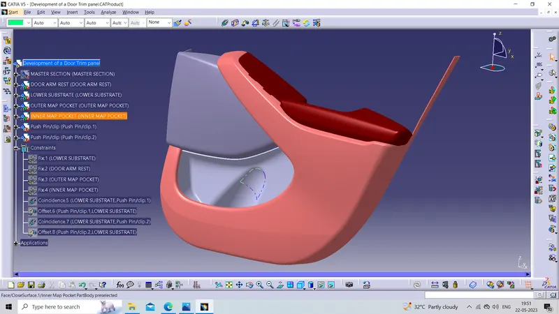
FRONT VIEW
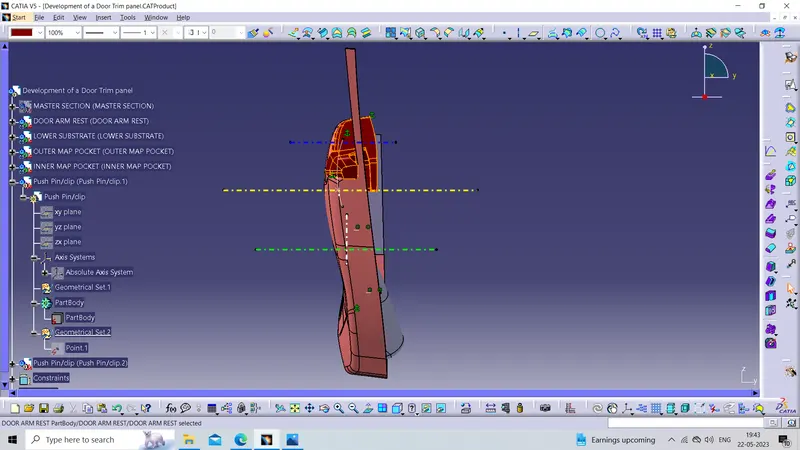
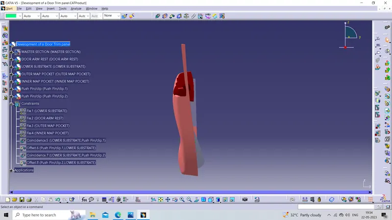
SIDE VIEW
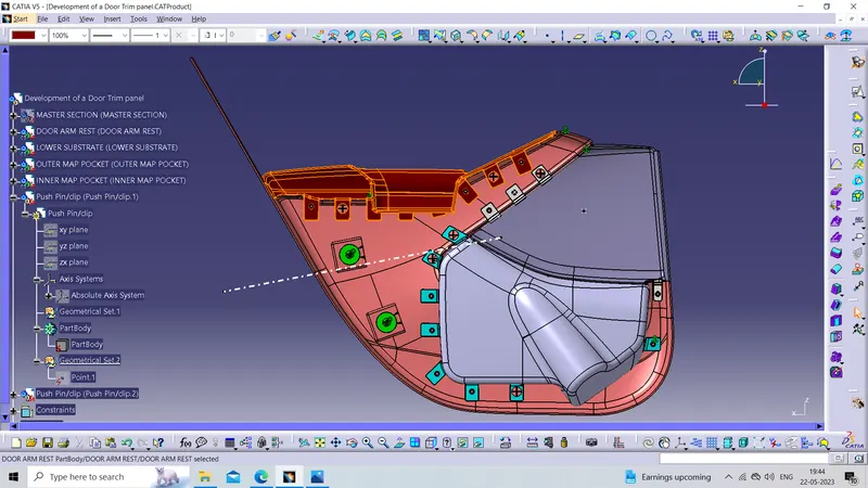
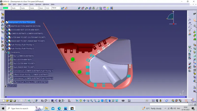
TOP VIEW
CONCLUSION:-
here I conclude that by using a Generative shape design Work Bench, Part Work Bench, and Assembly Workbench I successfully created a Door Trim panel by considering the following inputs as like in OEM and tier1 companies
a) Class A surface
b) Nominal thickness: Refer to aster sections
c) Attachment strategy :