Week 12- Final project
REPORT:
AIM:
To develop the assembly of door trim panel by using CATIA V5 design Software.
OBJECTIVES:
Creation of CAD model considering following inputs as like in OEM and tier1 companies
- a) Class A surface
- b) Nominal thickness : Refer master sections
- c) Attachment strategy :
Find a attachment strategy for the door panel complete work.
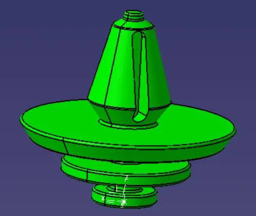
Use Push pin with Dog house for Lower substrate – Door panel attachment
Use heat stakes for part to part attachment
OUTPUT REQUIRED:
- Create thickened part using master section for reference
- Create the mounting features as per design guidelines in the industry and with master sections
- Apply material details :
- Draft analysis & Tooling analysis
- Creation of parting lines and check tooling feasibility
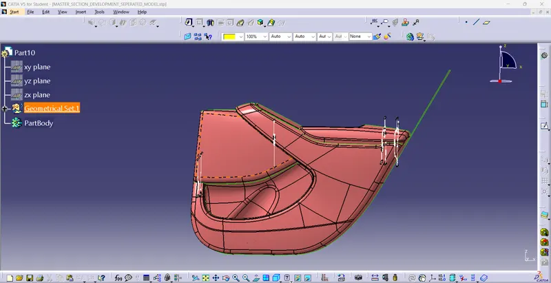
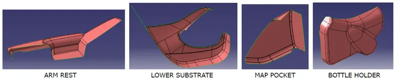
Given Class A surface:
TOOLING AXIS CREATION:
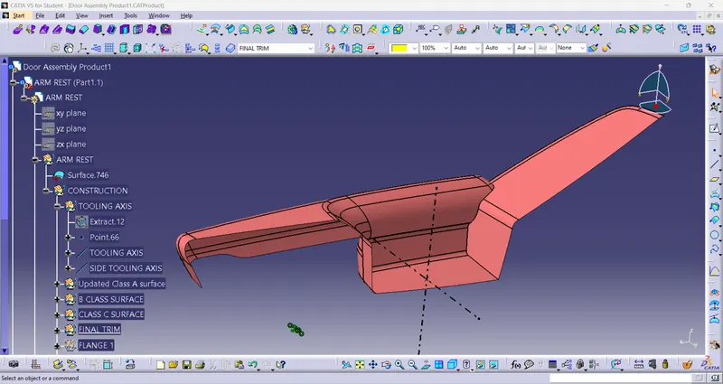
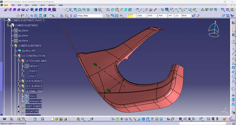
- Tooling axis is fixed in all individual component by looking at the view where the component looks complete.
- In this surface Y direction view is capable for that so decided to make a tooling axis line according to the Y direction.
- So, Extracted flat surface individually in all component and fix a point on surface and created a line of normal to surface.
- Now indicates that line as "Tooling Axis" Whereas Arm rest tooling axis is named as "side tooling axis" because it is located in side portion according to arm rest.
- Arm rest need another Tooling axis in Z direction.
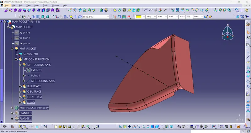
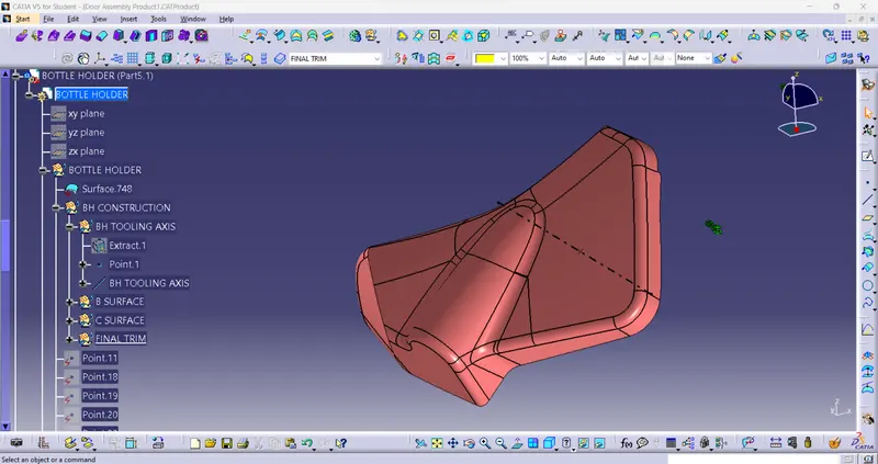
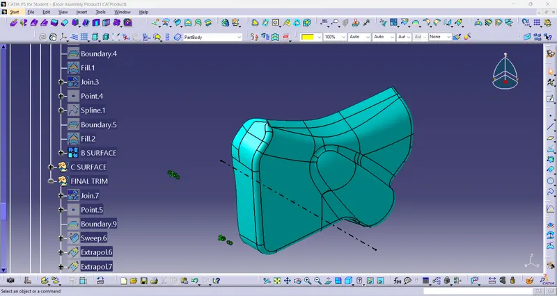
B SURFACE CREATION:
- B surface are build by taking offset from the given A surface.
- The offseted surface may come without some sub elements.
- That sub element should create by using Extract, Extraplote, Join,Trim command as per the design rules.
- After the build of sub element in the offseted part its should be extend through all edges by using extraplote and sweep command as per design rules.
- This extended process are done to get trimed with A+C surface.
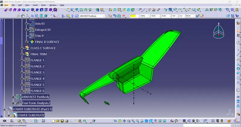
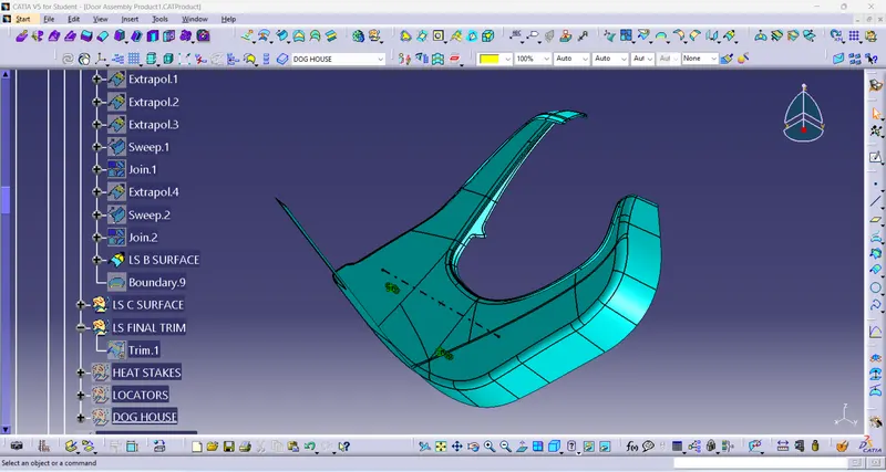
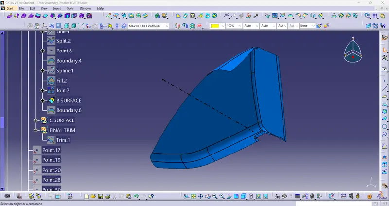
C SURFACE CREATION:
- This surface is created by taking reference as outer bounadary of Class A surface.
- Sweep command is used to enlarge the surface fom the boundary.
- It should be done according to the design rules where should be in 90* or 3* with draft direction or reference surface according to the surface.
- After the sweep process the edges of the sweep are extraplote and trimed.
- Then the trimed C surface and A surface are joined and name as "Join A+C".
- This process is done individually to all four surfaces.
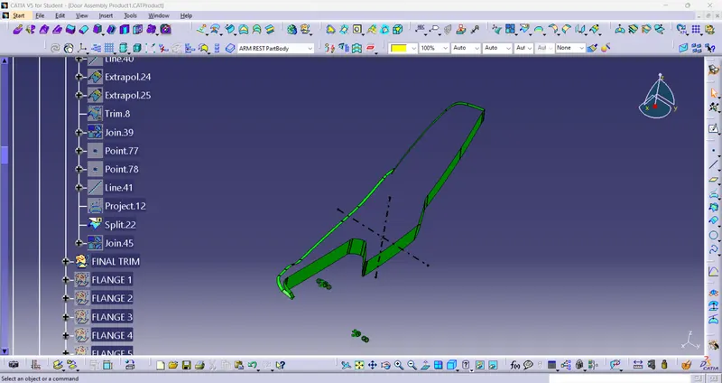

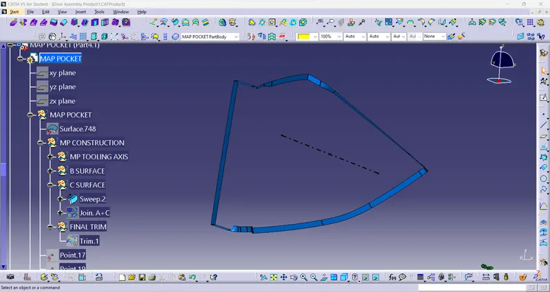
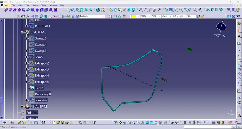
Parting line:
- Parting line is nothing but it is a intersection line between "Join A+C" and "B surface".
- This parting should complete without any interval of line.
- Then only the Final trim operation takes place.
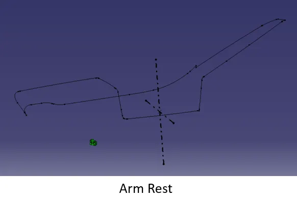
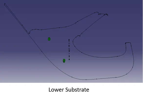
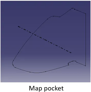
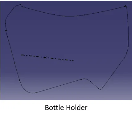
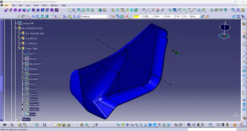
Final trim:
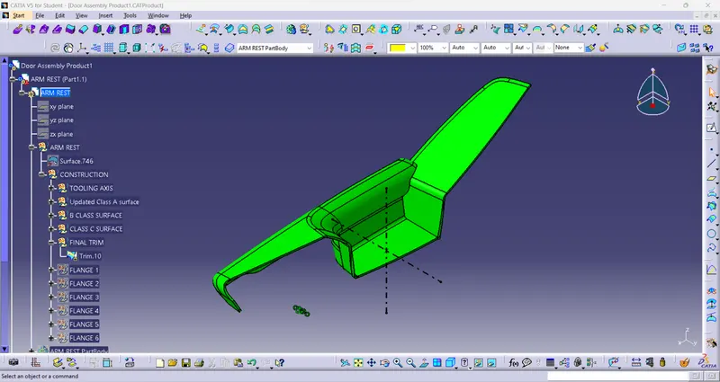
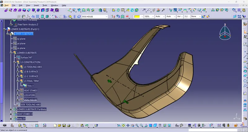
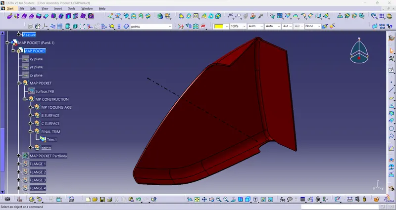
- The joined surface "Join A+C" are trim with B surface.
- This process should undertook without any boundary limit then only the next process closed surface should happen.
- So after that check it by using boundary command.
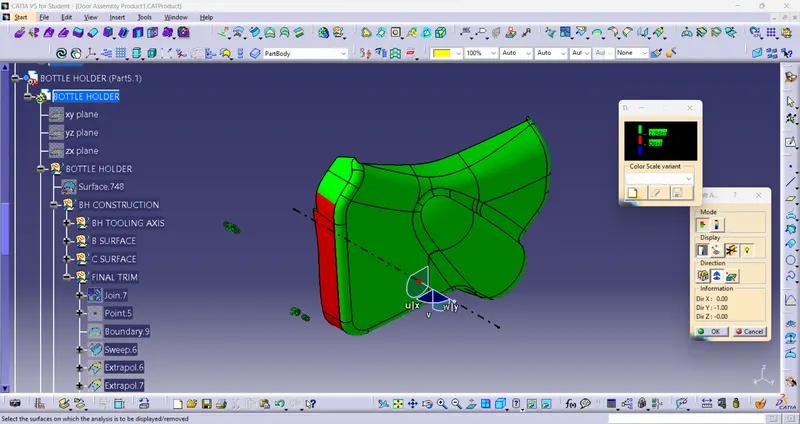
DRAFT ANALYSIS:
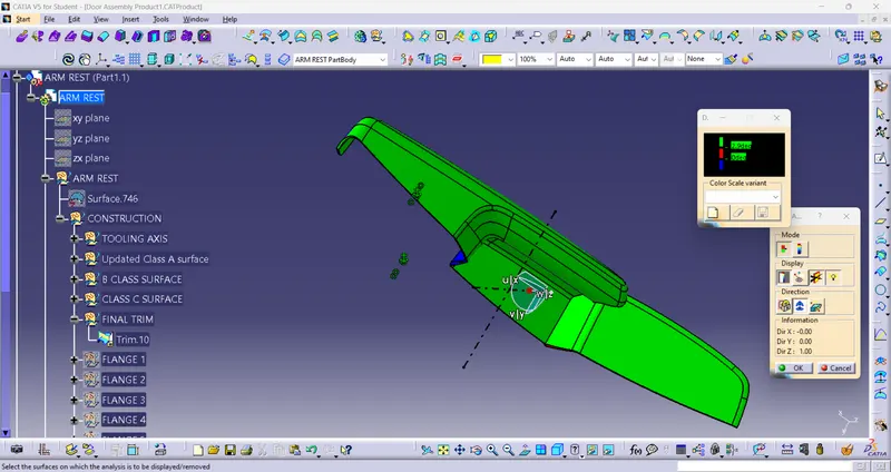
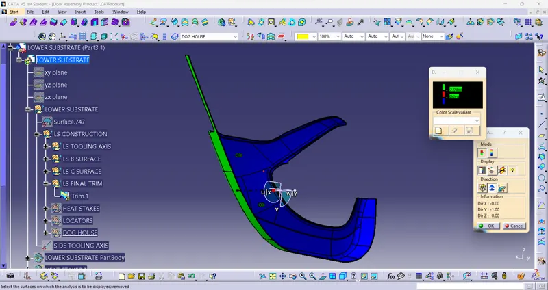
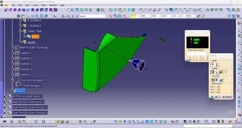
- The draft analysis technique is used to analyze whether our part model created in Catia is manufacturable based on the draft condition applied.
- First fix the compass in the tooling axis line by selecting the compass in the draft analysis and check the A surface first.
- If there is any mistake it visually evaluates surface draft-angle using false-color analysis (red).when this A surface is cleared then only we have go to next step.
- Angle also be checked in given class A surface then class B and class C surface are developed.
- After the development of class B and C again the Checking process in draft analysis are held.
- Then the mistakes are cleared and get back to draft analysis for checking it should be in green in upper cavity surface and blue in lower mould surface.
- This process is done individually to all four surfaces.
NOTE: Some parts may be defective after counselling to the Mentor they said it may be design problem from the given A surface. Kindly consider.
MASTER SECTION:
The Engineering attachment reference are taken from the given master section as follows:
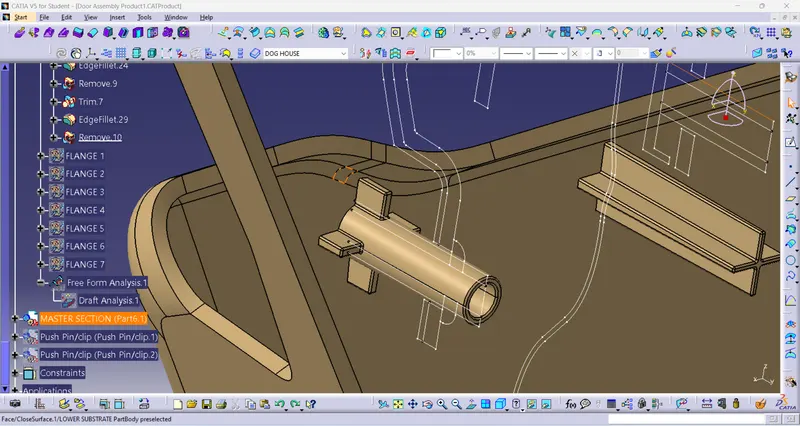
Heat stakes:
- The Heat stakes are sketched by taking reference from the given master section and paded according to the master section length.
- Then draft and filllet are done as per the design rules.
- After the one Heat stakes and Locator are build it is copied and paste the point according to the flanges.
Flanges:
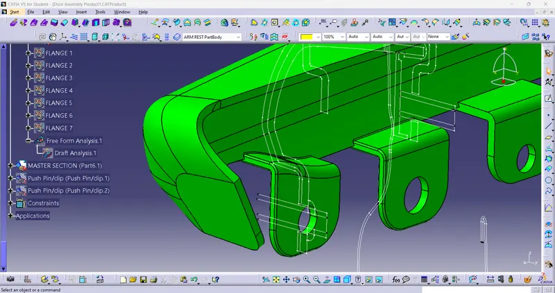
- The Flanges are sketched by taking reference from the given master section and paded according to the master section length.
- Then draft and filllet are done as per the design rules.
- This flanges are not like heat stakes its should be sketch paded again and again according to C surface of the component.
- This process is done individually to all four surfaces.
ENGINEERING ATTACHMENTS:
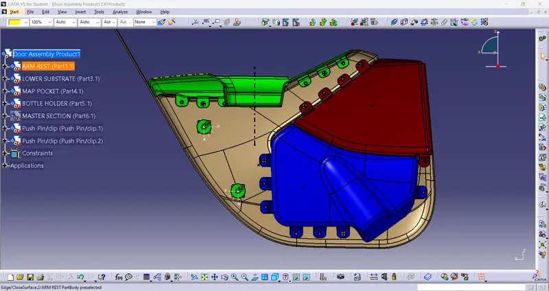
- This are the attachments which used to fix the compents while assembling as a part to part attachment.
- In this Door assembly Lower Substrate is a primary part because the heat stakes, locator and Dog house are attached here.
- The other components should only have Flanges.
- This Flanges,Heat stakes, locator and dog house are should be done taking reference from master section and draft analysis taken according to the design rules (0.45 degree).
- At the end the push pin are placed and inserted in the Dog house.
- This push pin are placed in product assembly by existing component of push pin and coincidence constraints.
- Then placed on the top of the Dog house.
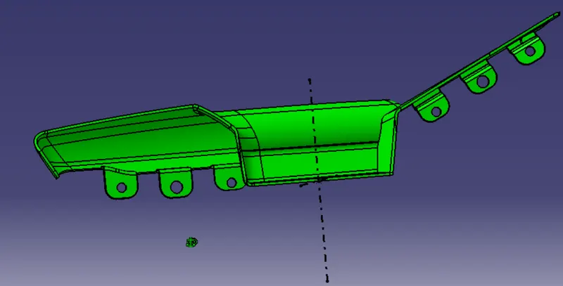
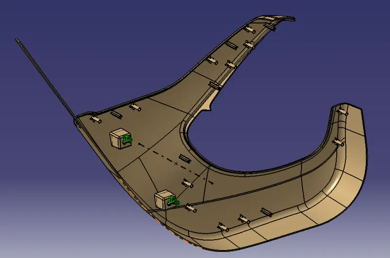
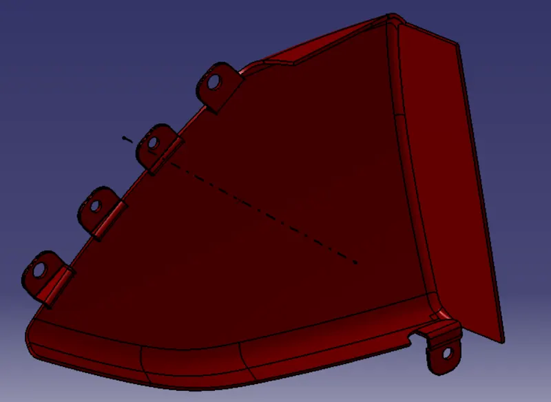
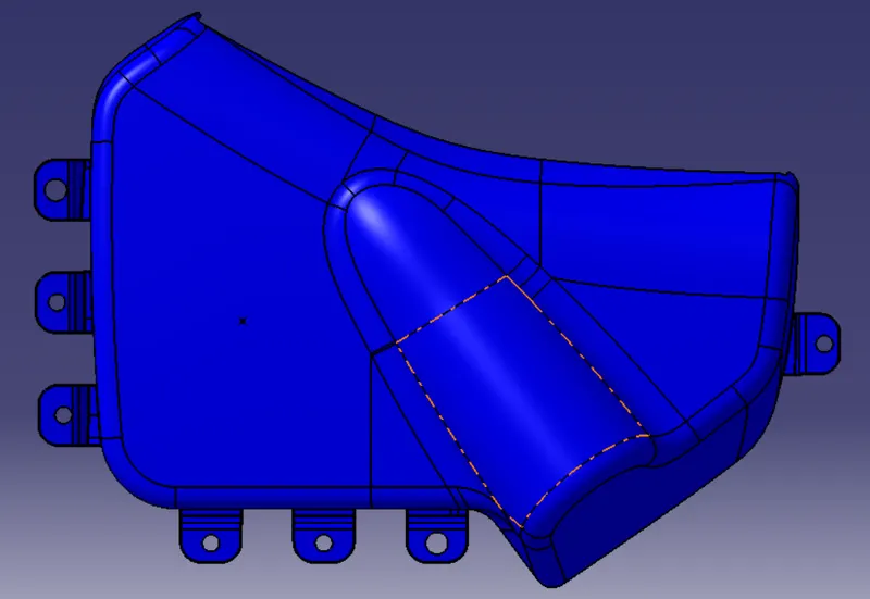
Result:
- The thickened part using master section for reference are created.
- The mounting features as per design guidelines in the industry and with master sections are created.
- The material detail Draft Analysis and Tooling axis are applied.
- Parting lines are created to check tooling feasibility.
- Master section reference are taken to build Engineering attachments.
- Heat stakes are used for part to part attachment.
- Push pin with Dog house for Lower substrate are used.
***
Note: The entire 'Save management' folder are attached.