Week 8 - Challenge 4 - Bumper
Screenshots of the Draft analysis report for both the given Class-A surface and the final plastic component
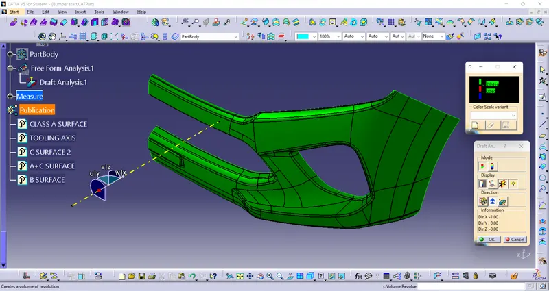
Class-A Surface
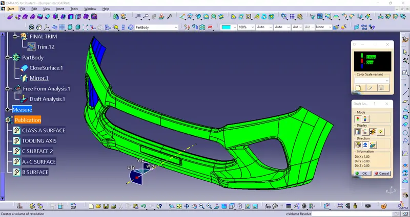
Final plastic Component
Screenshots of the solid model with the proper color code of the draft angle in various orientations (Isometric, Front, Side, and Top View)
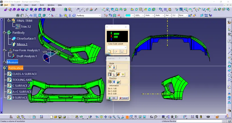
Report:
1.) Creation of Tooling Axis 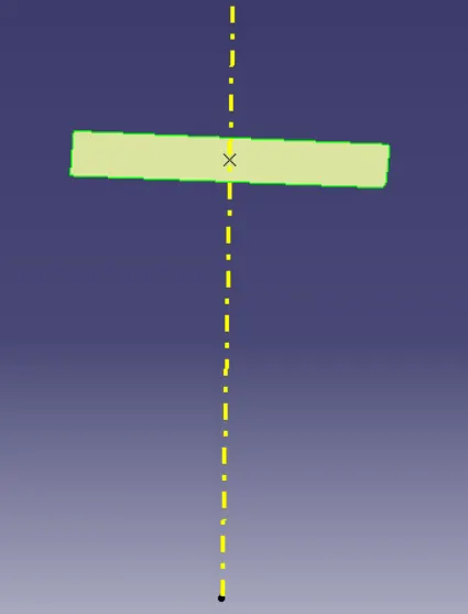
i.) First visually checked where does the tooling axis should be provide by checking the direction and holes.
ii.) In this surface there is a flat surface (Number plate surface) in the top. so, decided to fix the tooling axis on that surface.
iii.) Extracted that particular surface fix a point on surface and created a line of normal to surface.
iv.) Now indicates that line as "Tooling Axis".
v.) Hence, the Tooling Axis is created.
2.) Creation of Draft Analysis 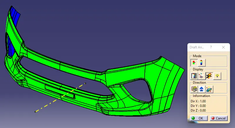
i.) The draft analysis technique is used to analyze whether our part model created in Catia is manufacturable based on the draft condition applied.
ii.) First fix the compass in the tooling axis line by selecting the compass in the draft analysis.
iii.) Angle also be checked in given class A surface then class B and class C surface are developed.
iv.) After the development of class B and C again the Checking process are held.
v.) If there is any mistake it visually evaluates surface draft-angle using false-color analysis (red).
vi.) Then the mistakes are cleared and get back to draft analysis for checking it should be in green in upper cavity surface and blue in lower mould surface.
vii.) Hence, the process
***
Note: It is not clearly mentioned that the attachment file should be in original or in zip file. so, attached that both kindly please check it.