Week 12- Final project
DOOR TRIM PANEL
AIM:
To create a solid body of Side Door plastic trim including the engineering features using the given Class A surface and master section and adding thickness to the component by Catia v5.
SIDE DOOR:
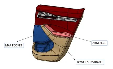
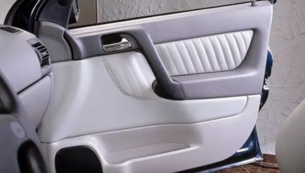
Door panels serve as an interface between the interior of the car and the inner workings of the door, and between vehicle occupants and the door. They are expected to meet a variety of design specifications regarding safety, aesthetics, and functionality. In addition, they are expected to continue the material theme of the dashboard and pillars while concealing intricate electrical and mechanical components for operating locks, windows, and other features. The door panel has evolved from a simple two-part system of latch and simple winding mechanism to a more sophisticated enclosure. Doors currently have an inner full-width panel consisting of arm rest, lower substrate, map pocket, bottle holder, electronic windows, central locking system, and speakers. These panels typically consist of a foamed core covered with either textiles or plastics.
CLOSED BODY CREATION:
To create the component through the given Class-A surface. Desired thickness of the plastic component is 2.5mm.
CLASS A SURFACE:
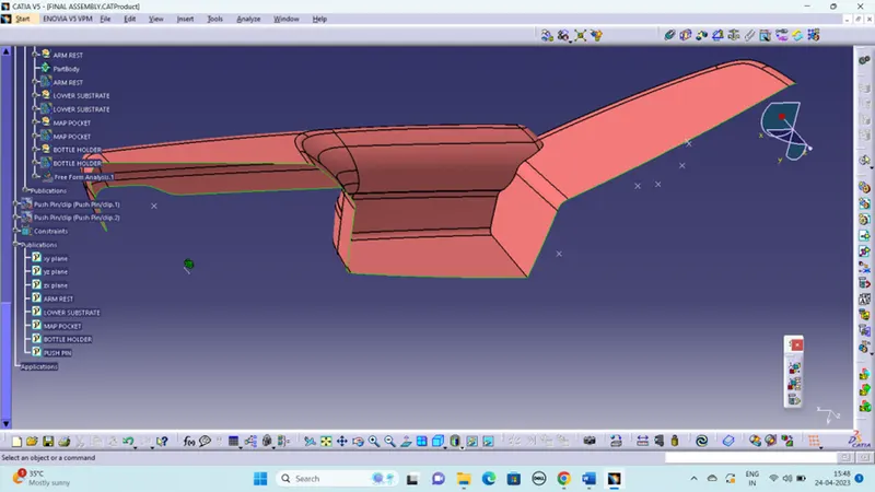
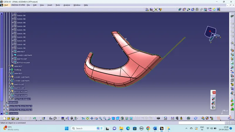
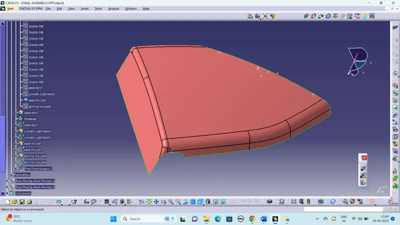
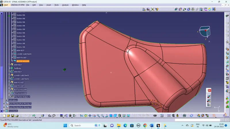
Class A is an aesthetic surface with the highest quality finish. Most Class A Surfaces for an Automotive Component are made using AUTODESK ALIAS. It is taken as a reference by the Automotive Plastic Designer to create CLASS B, CLASS C surfaces.
CLASS A FOR ARM REST:
CLASS A FOR LOWER SUBSTRATE:
CLASS A FOR MAP POCKET:
CLASS A FOR BOTTLE HOLDER:
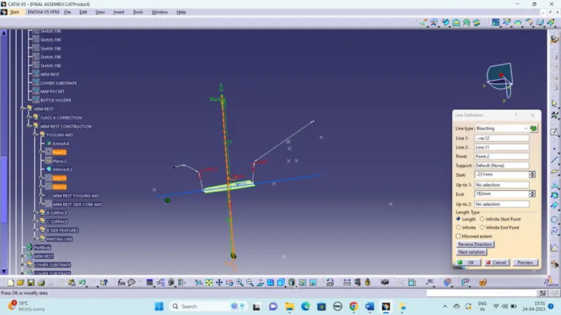
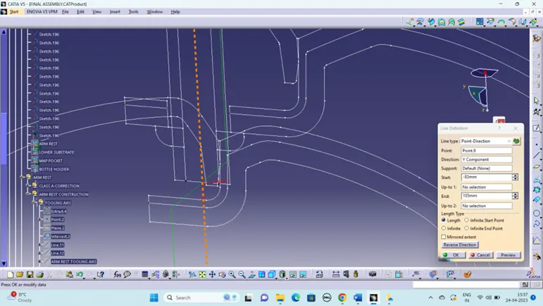
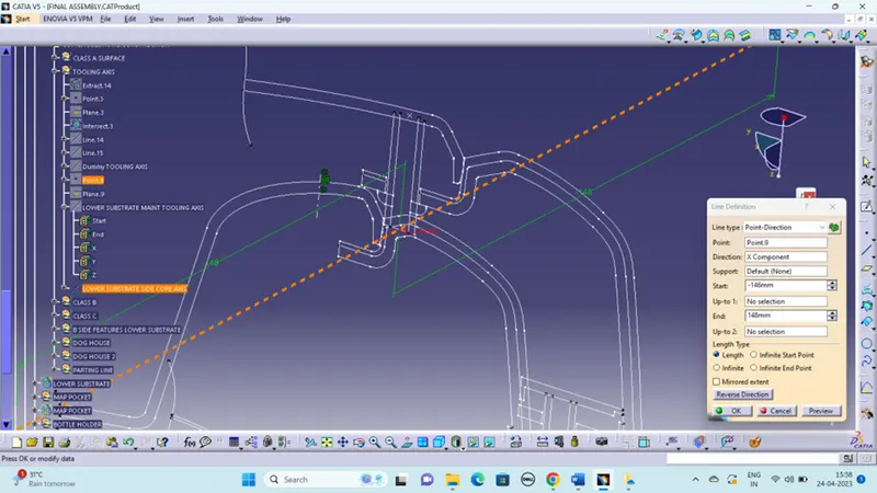
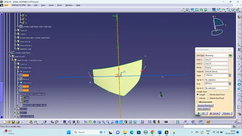
TOOLING AXIS:
Tooling axis is the direction in which a core or cavity of mold opens. This Axis is very important to determine the orientation of the component in mold, core and cavity design as well as to run the draft analysis of the component.
BISECTING METHOD:
- In this way first I create the point (on surface) in the extracted surface.
ARM REST TOOLING AXIS:
LOWER SUBSTRATE TOOLING AXIS:
LOWER SUBSTRATE SIDE CORE AXIS:
MAP POCKET TOOLING AXIS:
BOTTLE HOLDER TOOLING AXIS:
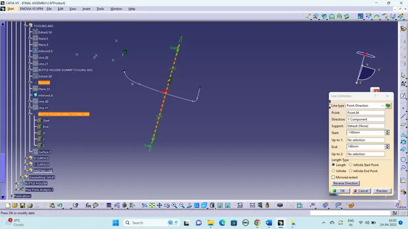
CLASS B SURFACE:
The thickness of the component as 2.5mm. Now we need to create a B surface which will be similar to the A surface at an offset value of 2.5mm. there are some discontinuities happened while offsetting the CLASS A surface so I repaired it to form a closed boundary by using the multiple extract, extrapolate, trim and fill surface commands and tools.
ARM REST CLASS B SURFACE:
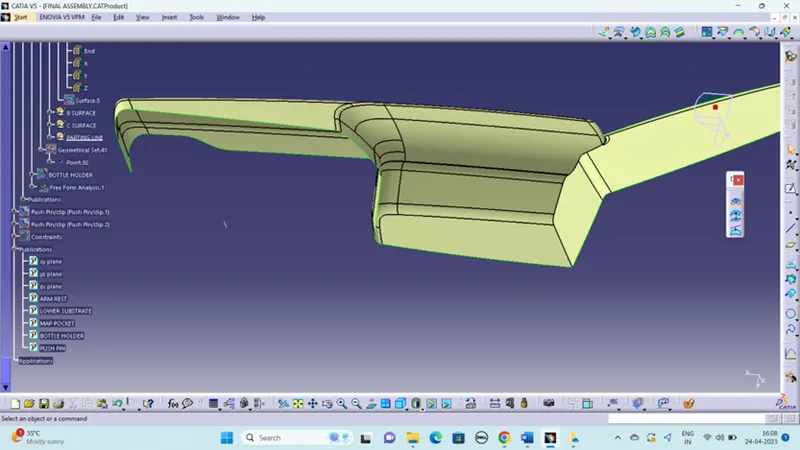
LOWER SUBSTRATE CLASS B SURFACE:
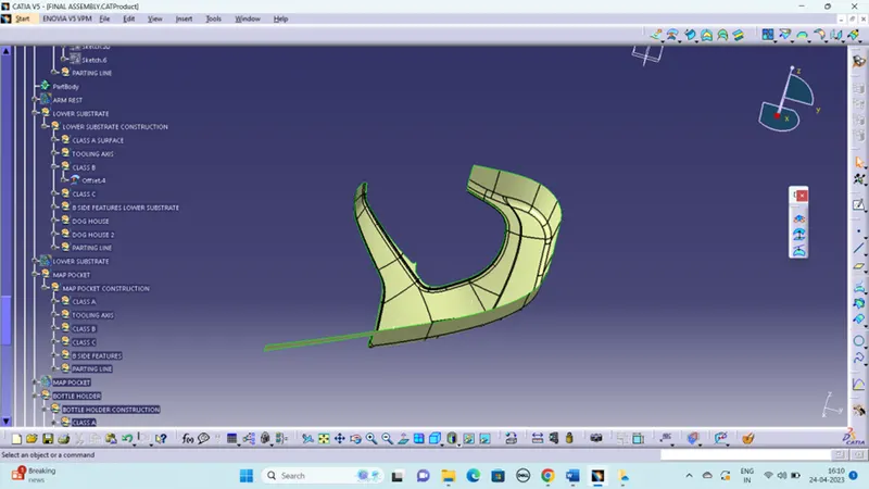
MAP POCKET CLASS B SURFACE:
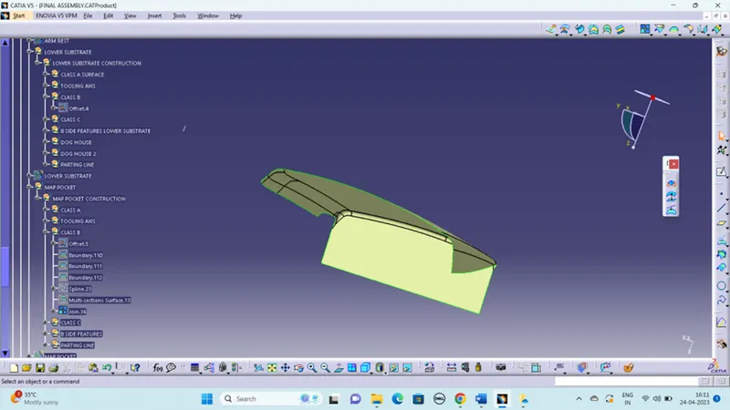
BOTTLE HOLDER CLASS B SURFACE:
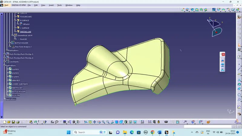
C SURFACE:
C surface is created with help of A-Surface by using the Sweep(with reference surface) and Boundary command separately, finally joined together to get the final C surface.
ARM REST CLASS C SURFACE:
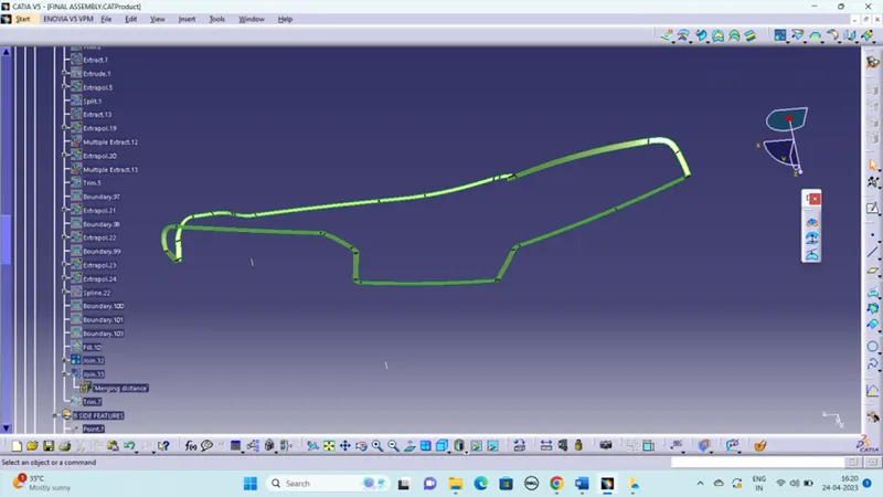
LOWER SUBSTRATE CLASS C SURFACE:
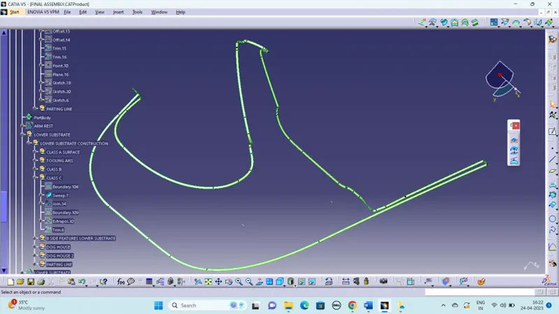
MAP POCKET CLASS C SURFACE:
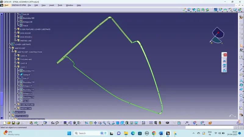
BOTTLE HOLDER CLASS C SURFACE:
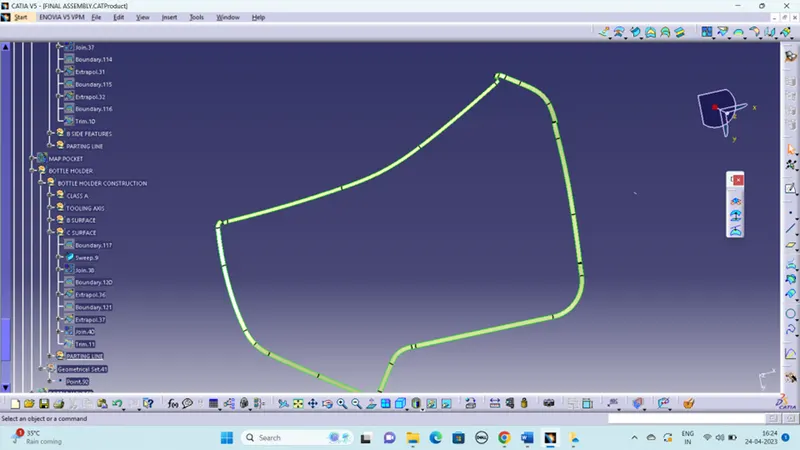
CLOSED SURFACE:
Then join the class A surface to the class C surfaces after that I trim out the joined A and C surface to class B surface to get the final object.
ARM REST CLOSED SURFACE:
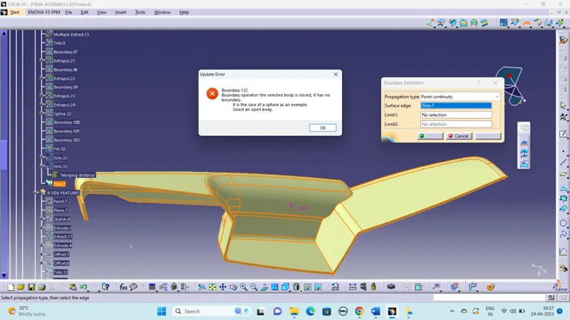
LOWER SUBSTRATE CLOSED SURFACE:
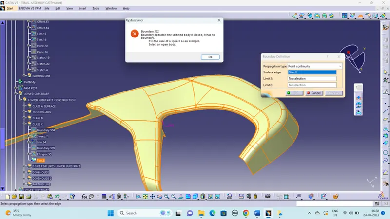
MAP POCKET CLOSED SURFACE:
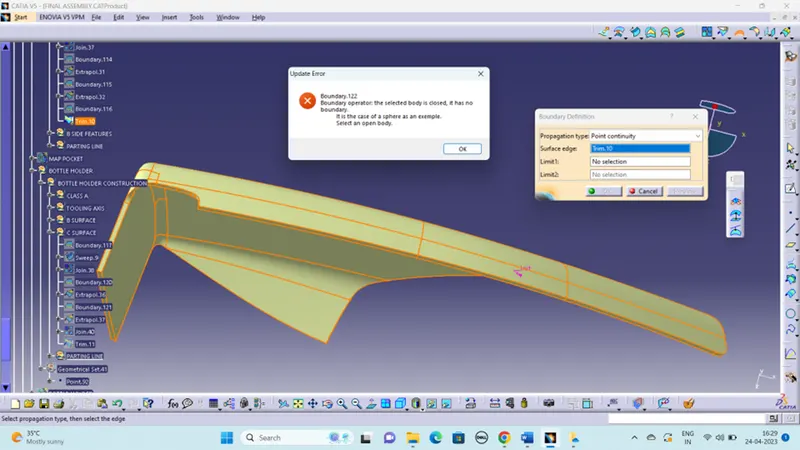
BOTTLE HOLDER CLOSED SURFACE:
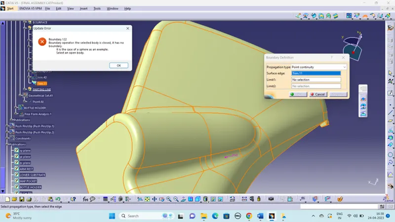
B SIDE FEATURES CRTEATION:
CREATION OF LOCATORS:
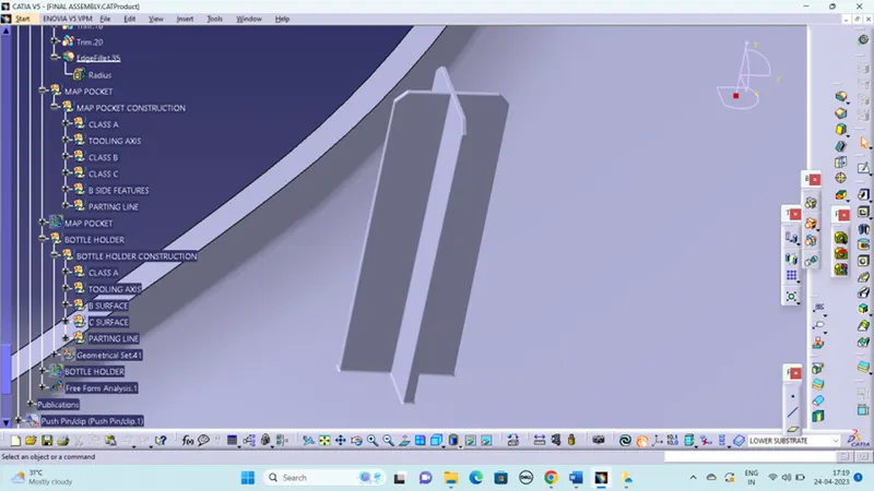
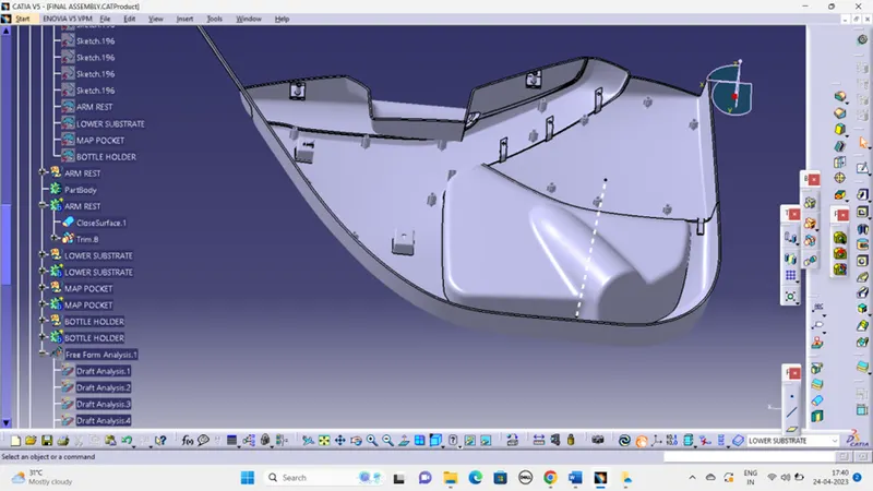
To create the locators, I created a sketch on the body. After creating the sketch, I pad it 28mm in height and thicken it to 1.25mm and I drafted it with 0.5deg in the direction of the tooling axis. I gave 1mm of chamfer with 45deg of inclination and after I gave a fillet of 0.3mm radius.
CREATION OF HEAT STAKES:
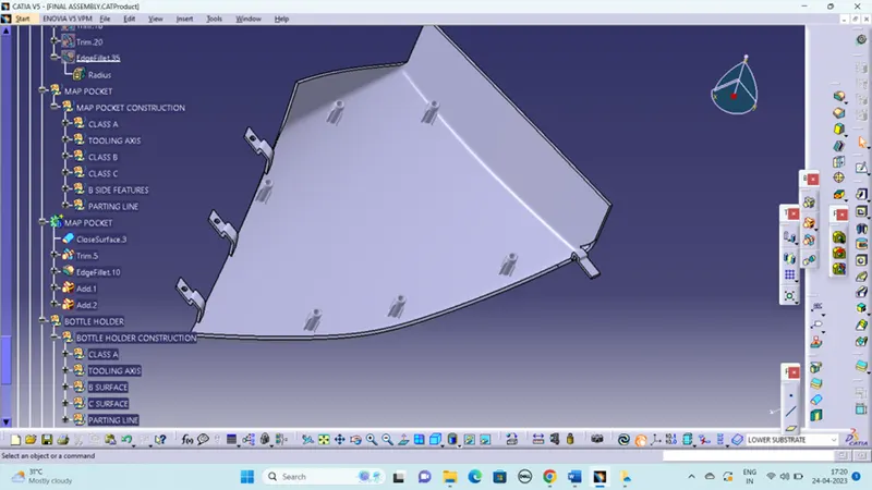
To create the heat stakes, I draw a sketch on the surface. After the creation of the sketch, I pad it to 18mm height and I gave a draft angle of 0.5deg on both sides (inside and outside) and then I gave a fillet with a 0.3mm and 1mm radius. After creating the heat stake, I created the ribs for supporting purposes. To create the ribs, I draw a sketch and padded it to 12mm in height and 1mm in thickness. After padding the ribs, I drafted 0.5deg in the tooling axis direction and filleted it with a 0.25mm radius. Finally, I union trim the ribs with a heat stake to remove the ribs, which are present inside the heat stakes.
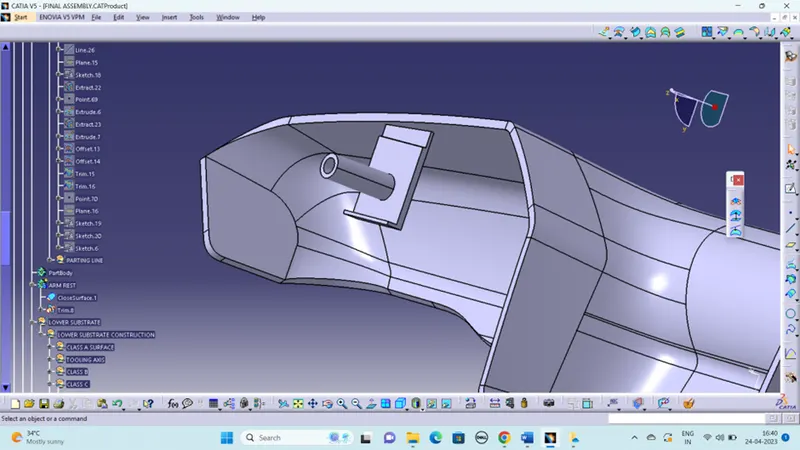
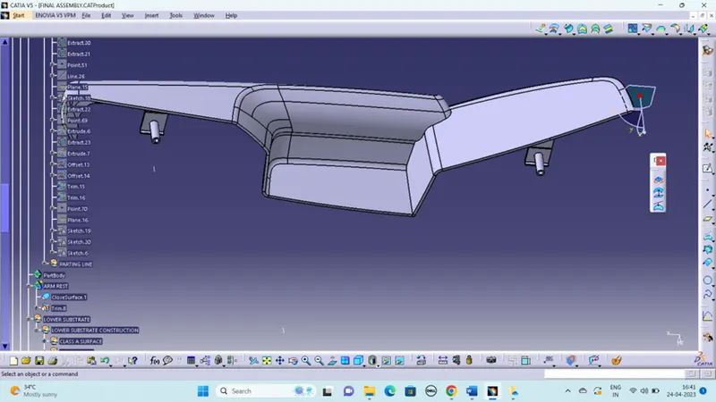
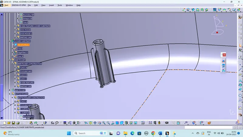
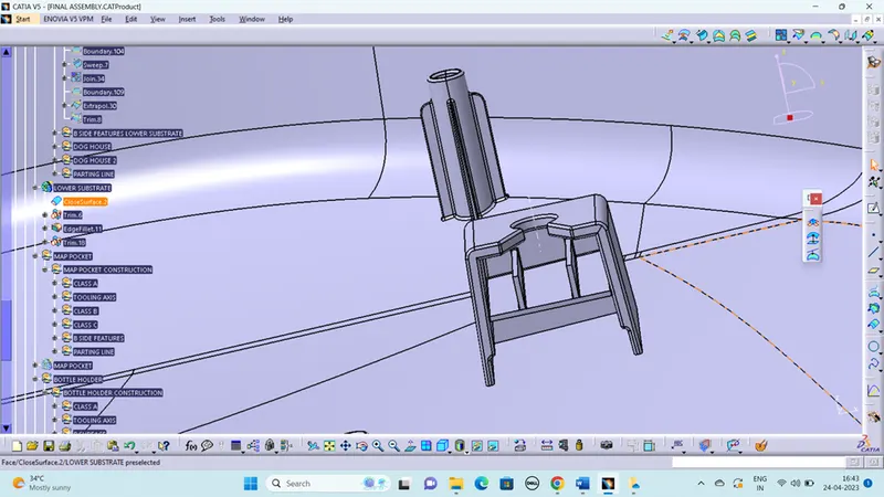
DOG HOUSE
Dog house is an engineering feature used in plastic design. Dog houses are used as support feature. Sometimes other engineering features like snaps, locators, screw bosses are mounted on them to increase their strength.
Dog houses are subjected to draft analysis to prevent breakage of the component during ejection from the mould cavity. Dog house and oher engineering components are built on the B-surface
- Dog houses are designed to avoid SINK MARK created on the CLASS-A surface by screw bosses and to solve the length issues when giving screw bosses which need to be assembled to other components.
- It is also useful when perpendicular screw bosses are required on the part to the tooling direction.
- Make a rectangle to enclose the screw boss in it but make sure it is open from one side.
- Sweep it with tooling axis as the pulling direction inwards.
- Close the top face by using multi section surface.
- Thicken it by 2.5 mm to the outward direction.
FOR ARM REST:
FOR LOWER SUBSTRATE:
FOR MAP POCKET:
FOR BOTTLE HOLDER:
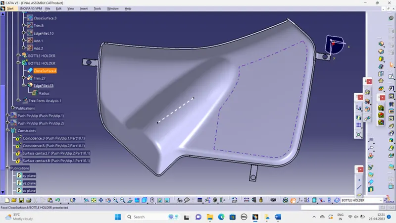
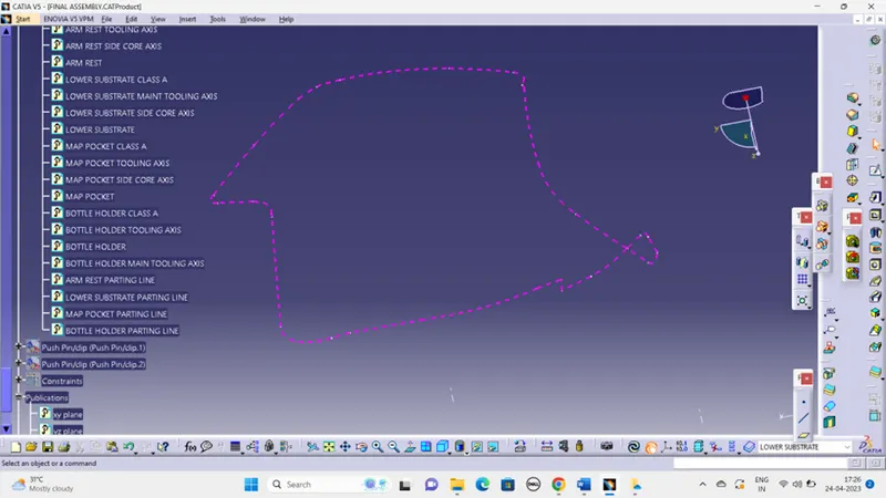
PARTING LINE:
The parting line indicates the direction of the line of draw for the mold, or the point where you can separate the two halves of the mold to release the part without damage. Usually, the parting line is down the middle of the part, but this varies due to part geometry
ARM REST PARTIN LINE:
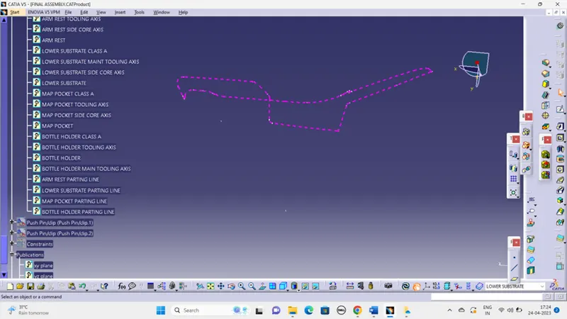
LOWER SUBSTRATE PARTING LINE:
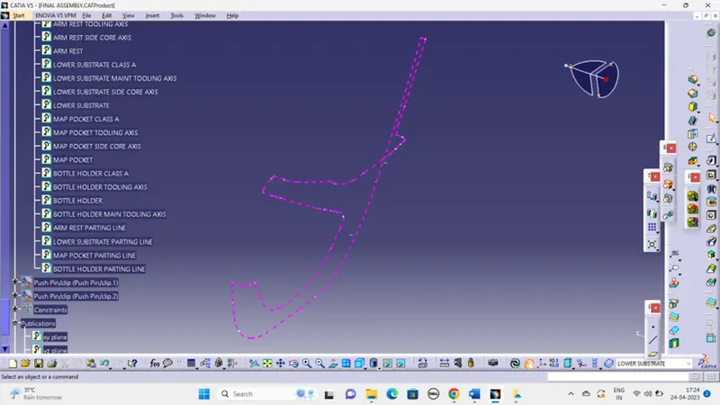
MAP POCKET PARTING LINE:
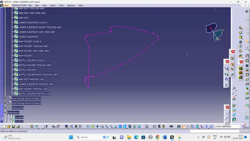
BOTTLE HOLDER PARTING LINE:
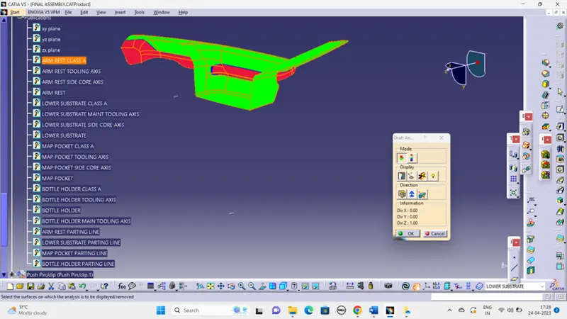
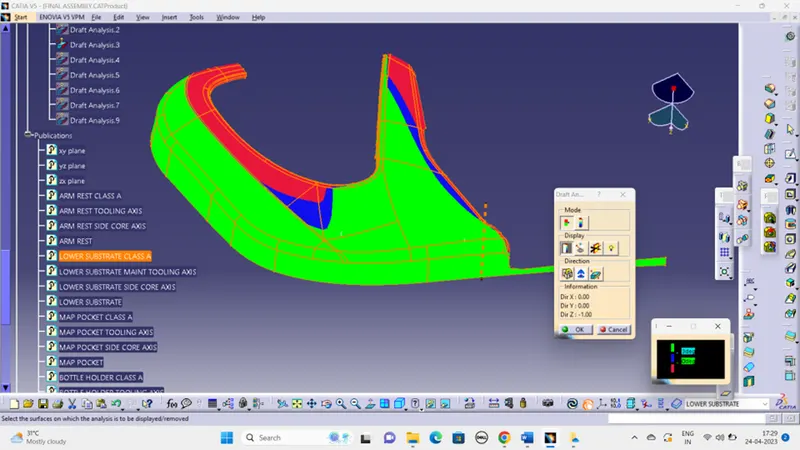
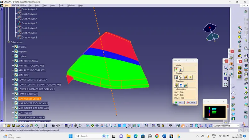
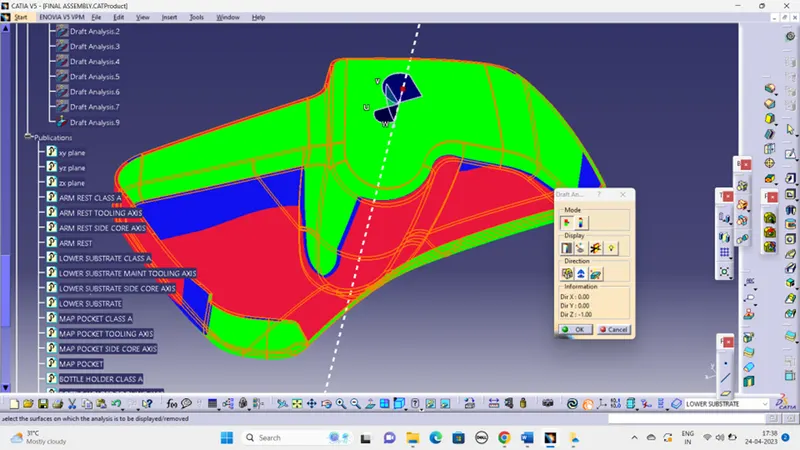
DRAFT ANALYSIS FOR CLASS A SURFACE:
FOR ARM REST:
FOR LOWER SUBSTRATE:
FOR MAP POCKET:
FOR BOTTLE HOLDER:
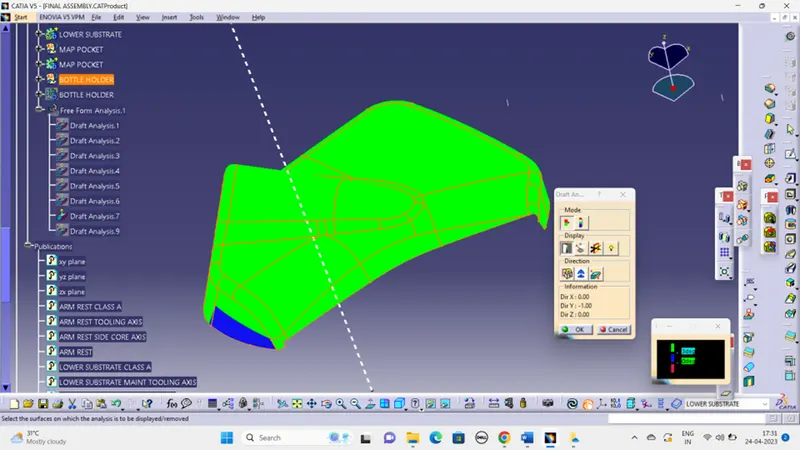
DRAFT ANALYSIS FOR CLOSED SURFACE:
FOR ARM REST:
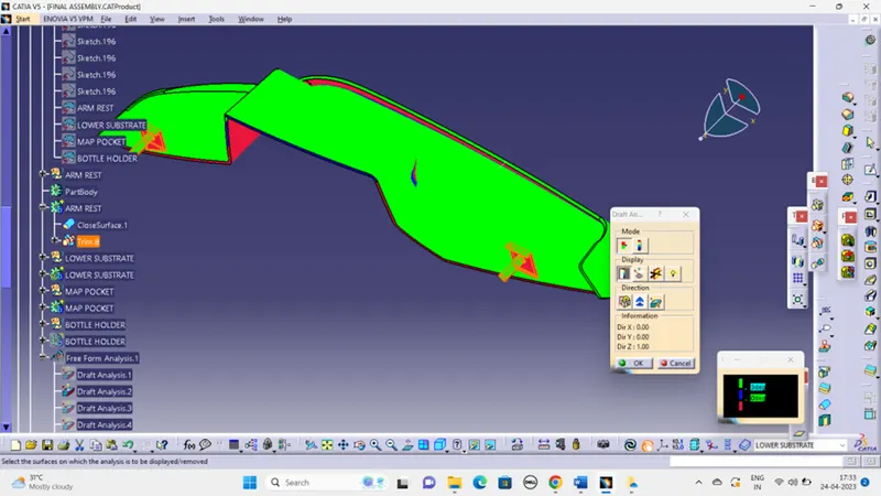
FOR LOWER SUBSTRATE:
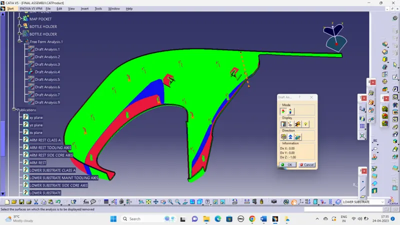
FOR MAP POCKET:
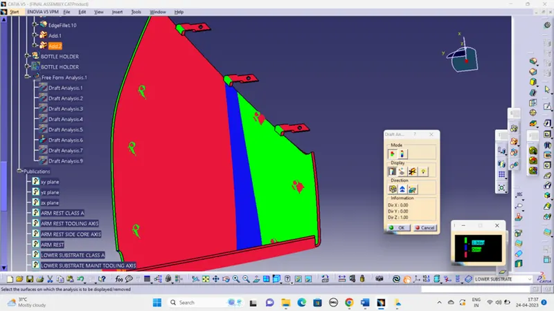
FOR BOTTLE HOLDER:
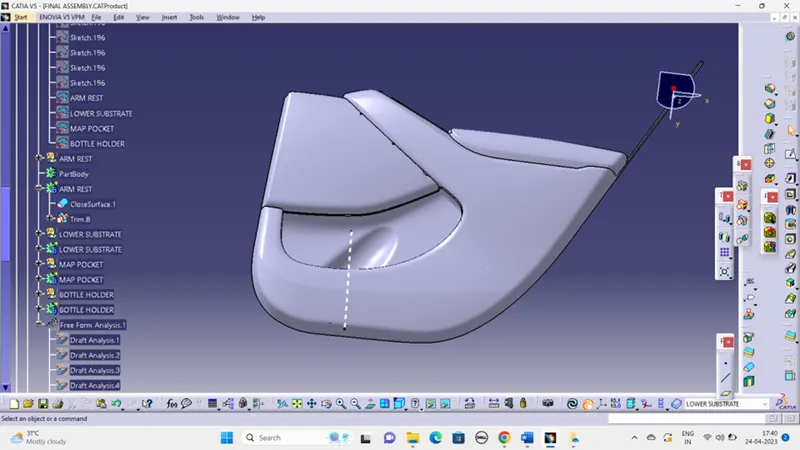
FINAL BODY:
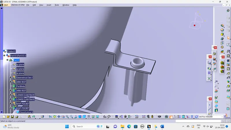
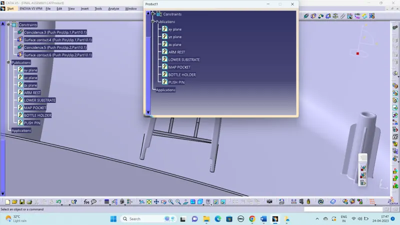
ASSEMBLY OF PUSH PIN:
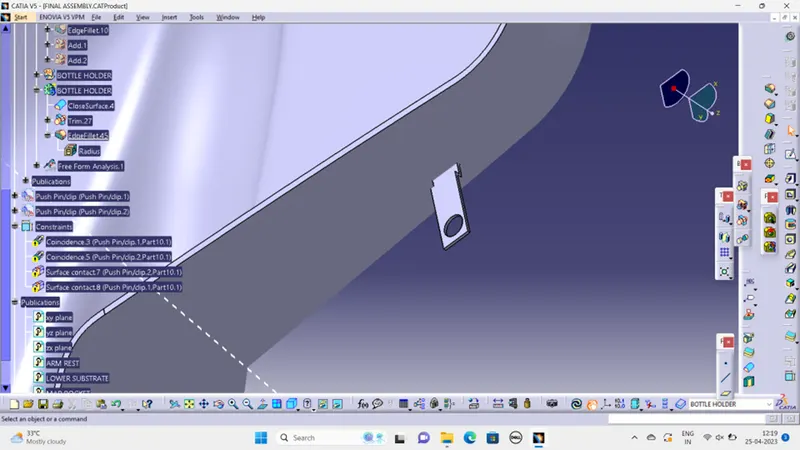
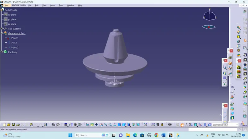
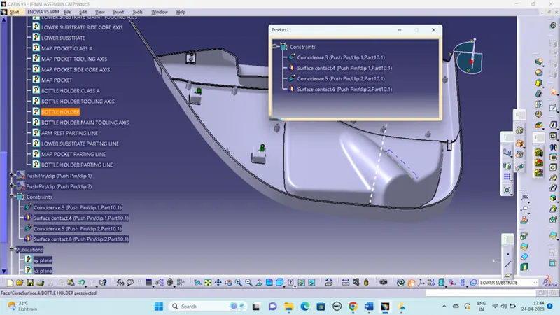
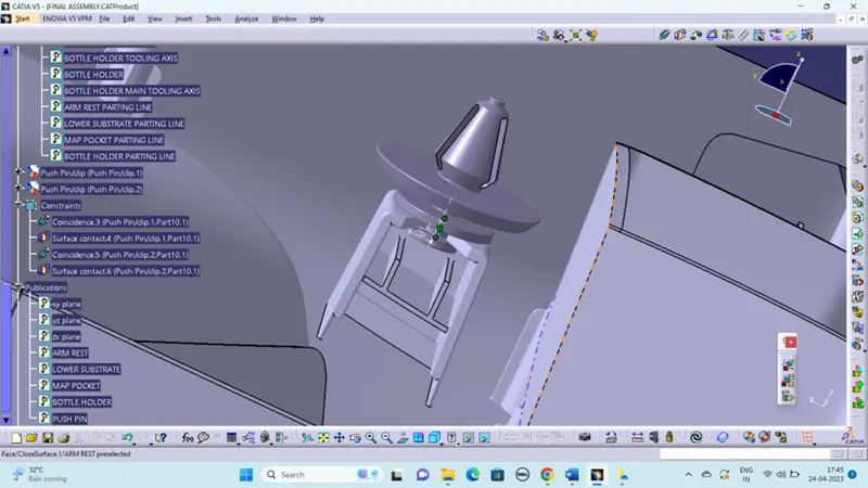
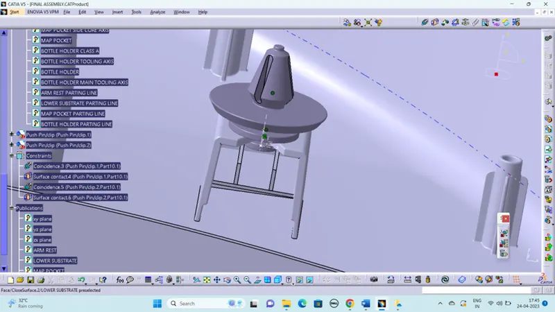
Push pins are designed in this project to attach the front panel with the sheet metal. It is designed on top of the dog houses.
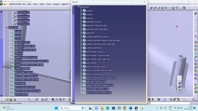
PUBLICATION: