Week 12 Challenge
Q-1 Design isolated footing for a column 300 mm x 450 mm, carrying axial load of 1500 kN and Mu = 150 kNm using STAAD. Foundation. Assume that the moment is reversible. The safe bearing capacity of the soil is 200 kN/m2 at a depth of 1 metre from ground level. Use M 25 and Fe 415 for the footing. Also validate the design through hand calculation.
AIM & INTRODUCTION:
Isolated footing is required to be designed using STAAD.Foundation with following given data/inputs-
Size of column : 300 mmx 450 mm
Axial load : 1500 KN
Moment `M_u` : 150 KNm ( Reversible)
SBC of soil : 200 KN/`m^2` at a depth of 1 m from ground level
Grade of concrete : M25
Grade of steel : Fe 415
Design is also to be validated through hand/manual calculation
PORCEDURE IN DETAIL:
Double-clicking the STAAD Foundation Advanced icon to open .
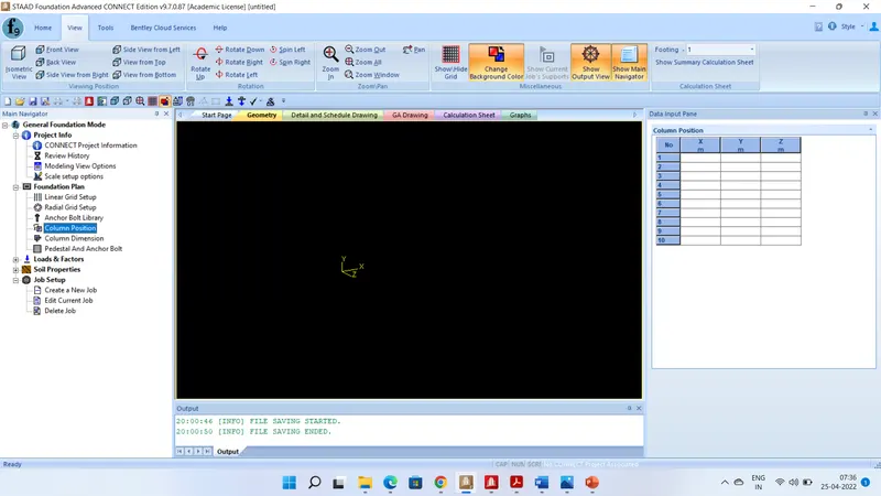
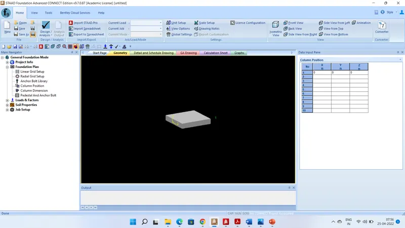
Select General foundation mode
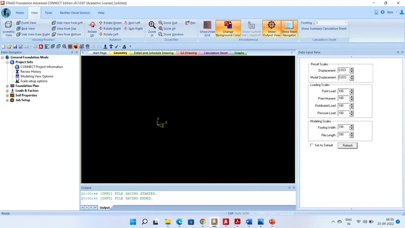
Add general info about a project, create a revision history for a project, and access view and scaling controls. The Project Info group is not active in the software programme installed on my lap top
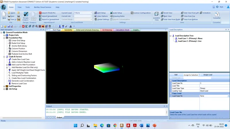
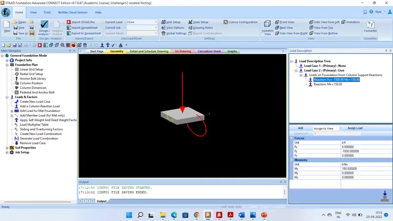
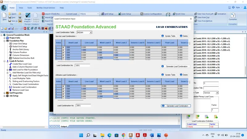
A Table under the load description area will appear allowing to create a new load case.
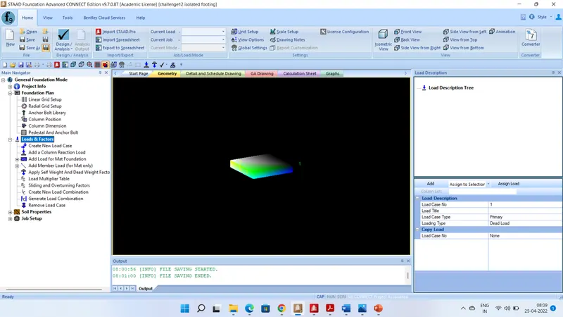
3.Type Load Case 1 for Load Title
4.Select No for the Add Self Weight field.
5. Click on the Add button to have the load case created.
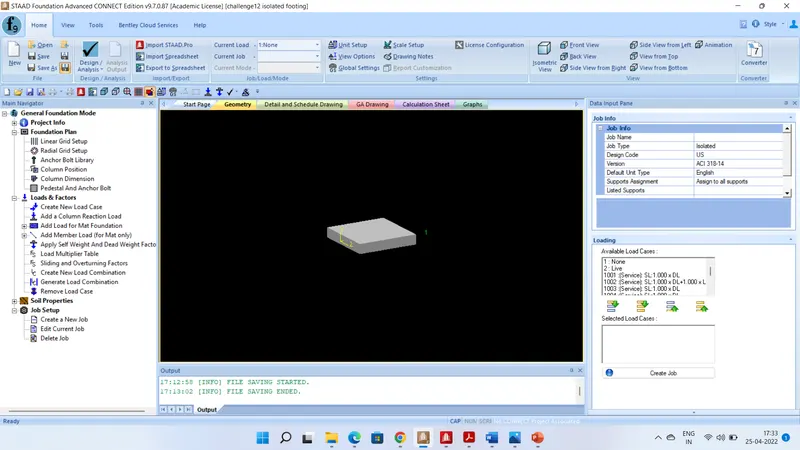 3.Enter Job1 for the Job Name.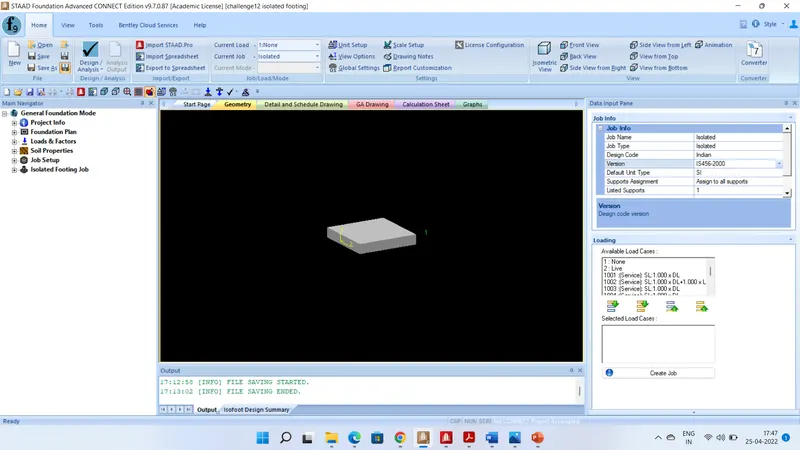
Entering Design Parameters
Job Setup allows usto create a new job or edit an existing job. It is only when you create a New Job (a set of constraints for the program to use in performing a foundation design) that groups related to the current design process will appear.
Isolated Footing Job is created in the Main Navigator pane. This group allows us to enter design parameters like footing geometry, concrete cover, soil parameters etc.
Performing an Isolated Footing Design:
1. select the Isolated Footing Job > Design Parameters > Design in Main Navigator pane.A warning dialog opens to confirm you want to proceed with the design.
2.Click Yes.
Once the process is complete, the program will automatically display a Design Summary
3 save the project Press
RESULT : It is concluded that isolated footing is designed with given inputs and validated the staad.foundation design through hand calculation. Design summary is as follows-
Dimension of footing:
1) 3 mx 3 m
2) Over all depth of footing D = 650 mm
3) Depth of footing is checked for BM, Single shear & Double shear and found safe
4) No tension steel is needed as there is no negative pressure.
5) Development length = 648 mm
VALIDATION OF DESIGN THROUGH HAND CALCULATION
Footing should be symmetric with respect to column as the moment is reversible( `M_x & M_y` are same ,that is square footing is to be designed.
Service load = 1500KN
Considering Self weight of footing & weight of backfill soil = 10% of service load
P = 1.1x 1500= 1650 KN
`P_u`= 1.5x1650KN = 2475 KN
Area required = 1.1`P /(SBC)` = 1.1x1500/200 = 8.25 sqm`
`A_(cal)= 8.25 m^2`
Therefore L=B=`sqrt(A) = sqrt(8.25)= 2.87 m`
`provide square footing of size 3.0 m x 3.0 m
`A_(provided)= 9 m^2` > Area required which is 8.25 sqm (OK)
STEP-2 : NET UPWARD SOIL PRESSURE
`sigma(max, min)=P_d/A_(provided)+M_u/Z`
= (1.5x 1.1x1500/9) `pm`( 1.5x150/`(BxxL^2//6)` ( B=L=3 M)
= 275`pm`50
`sigma(max)`= 325 KN/ sqm < 370 KN/sqm ( Gross factored Bearing capacity) ( ok)
`sigma(min)`= 225 KN-m < 340 KN/sqm
Eccentricity e = M/P = 150/1500 = 0.1M = 100 mm
L/6= 3000/6 =500 mm
e < L/6 ,therefore no negative soil pressure will develop hence compression steel is not required.
STEP-3 DEPTH OF FOOTING ON THE BASIS OF B.M.
The maximum bending moment at the face of column (M)
= `P_0xx(B-b)^2//8` = `275xx3(3-0.3)^2//8`= 751.78 KNm
`M_u=0.138f_(ck)bd^2`
751.78`xx10^6` = 0.138x20x3000x`d^2`
d = 301 mm Say d = 305 mm
Adopt d = 600 mm due to shear consideration
Add effective cover = 50 mm
D = 650 mm
Depth of footing from one way shear-
d= `(P_u(L-a))/[2(P+tau_cxxL^2)]`
= 1.5X1.1X1500( 3-0.3)/2(1.5x1.1x1500+350x9)
= 6682.5/11250 =0.594 m = 594 mm < 600 ( OK)
Depth required for two way shear ( punching shear)
`P/L^2[L^2-(a+d)^2]= 4(a+d)d xxtau_p`
[`1.5x1.1x1500/9][(9-(0.3+0.6)^2]`= 4x0.9 x0.6`tau_p`
`tau_p`= 1043.98 KN/m^2 = 1.044 N/`mm^2`
Permissible `tau_p`= 0.25`sqrt(f_(ck)`
=0.25 `sqrt20`
= 0.25x4.472 = 1.118 N/`mm^2` > 1.044N/`mm^2` ( OK)
STEP-4: Reinforcement calculation
`A_(st) =(0.5f_(ck))/(f_y)[1-{1-(4.6xxM_u //f_ckBd^2)`
`A_(st)`= 5081 sqmm
p = `A_(st)/(Bxxd)xx100`
= (5081/3000x650)x100 = 0.26% > 0.12% which is min reqr , hence OK
`x_u/d =1.2-[1.44-(6.6M_u)/(f_(ck)xxbxxd^2)]^(1/2)`
`= 1.2 -[1.44-(6.6x751780x1000/20x3000x600x600)^0.5`
= 0.0998
Lever Arm Z = d(1-0.416`x_u/d)`
= 600( 1-0.416x0.0998)
= 575.089 mm
`A_(st) = M_u/(0.87xxf_yxxZ)`
= 751780X1000/0.87X415X575.089 = 3620.66 `mm^2`
STEP-5 : DEVELOPMENT LENGTH
As per IS 456: 2000,Cl 26.2.1.1
`sigma_s=415 N/(mm^2)`
`tau_(bd)`for deformed bar and M20 Grade of concrete = 1.92 N/`mm^2`
`L_d=(phixxsigma_A)/ (4tau_(bd)`
415`phi`/4x1.92 = 54`phi` = 54x12 = 648 mm for 12 mm dia bar
Q-2 Design a combined footing using STAAD. Foundation for two columns C1, 400 mm x 400 mm carrying a service load of 800 kN and C2, 300 mm x 500 mm carrying a service load of 1200 kN. The column C1 is flushed with the property line. The columns are at 3.0 m c/c distance. The safe bearing capacity of soil is 200 kN/m2 at a depth of 1.5 m below the ground level. Use M 20 and Fe 415 for columns and footing.
AIM & INTRODUCTION-
Combined footing is required to be designed for-
1. two columns C1 7 C2 having size 400 mmx 400 mm & 300 mmx 500 mm respectively.
2. Service load on C1 is 800 KN & on C2 is 1200 KN
3. Column C1 is flushed with property line
4. c/c distance between columns = 3.0 m
5. SBC of soil = 200 KN/`m^2` at a depth of 1.5 m
6. Grade of Concrete : M20
7. Steel grade : Fe 415
PROCEDURE IN DETAIL:
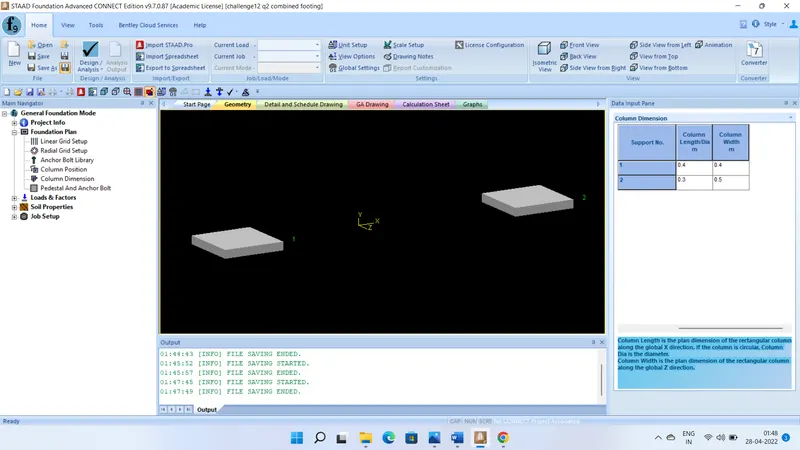
1. Column C1 & C2 are placed at a distance of 3 m and their dimensions are 400 mmx 400 mm & 300 mm x 500 mm respectively as shown below in print screen
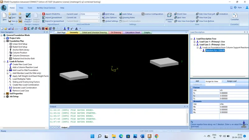
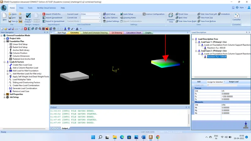
2. Two primary load cases as Live load as per given input have been created as shown below in print screen-
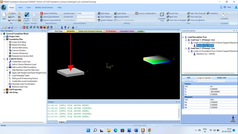
3. Assigning load of 800 KN on C-1 & 1200 KN on C-2 as shown below in print screen-
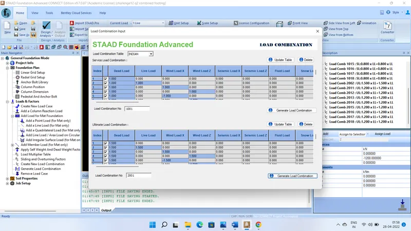
4. Assigning auto load combination as shown in screen print given below-
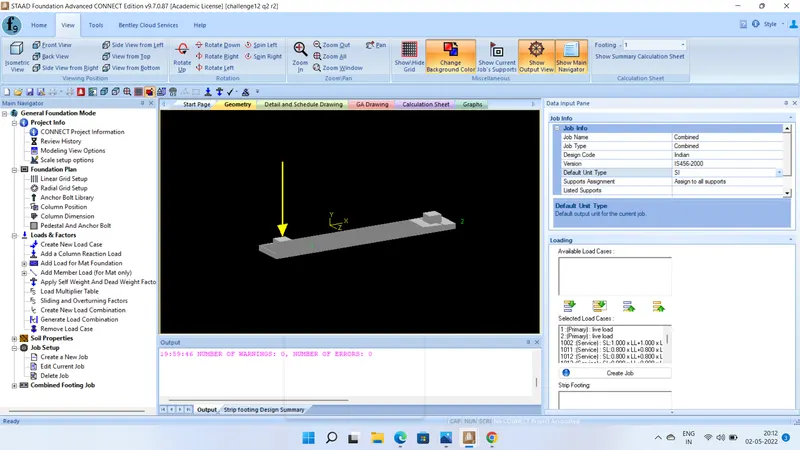
5.Creat a new job set up asigning job name as Combined, job type as combined, design code as Indian, Version as IS 456: 2000, Unit as SI etc as shown below in the print scereen-
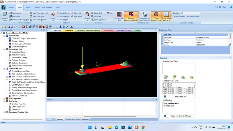
6. Edit current job under job set up then create strip footing after selecting both columns as shown below in print screen-
7. Under combined footin job assigning various design parameters viz.
a)unit weight of concrete
b)max and min spacing of bar
c)strength of concrete
d)yield strength of steel
e) min & max bar size
f) clear cover of pedestal & footing
g) unit wt and SBCof soil
h) depth of soil above footing
i) type of depth & water table depth
j) min % of contact area for service load
k) footing geometry such as overhang, min width, max length, width, max- min thickness, length and thickness increament etc. as shown in print screen given below-
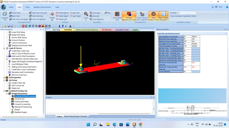
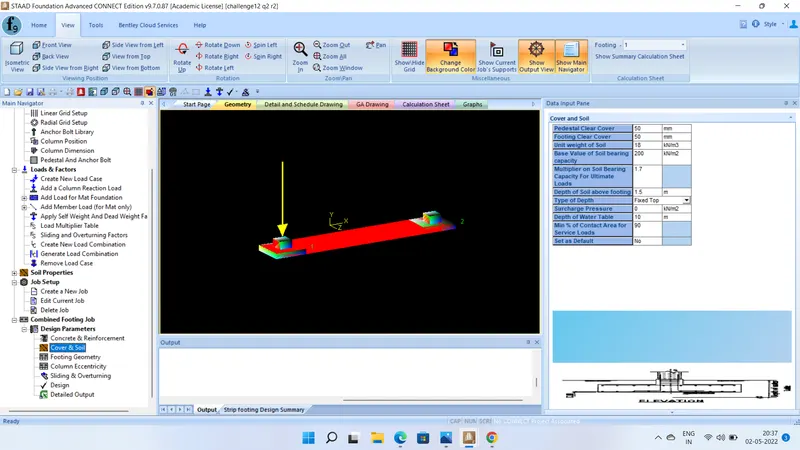
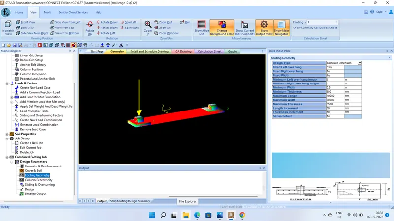
8. on giving design command output is obtained without anr warning and error as shown below-
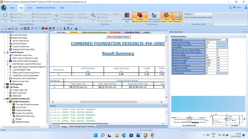
RESULT: It is concluded that-
Design is successful with footing dimension as 9.2m x 7.5 m and thickness 0.5 m. C-1 column is flushed with property line that is left over hang is 0.
main steel top 8mm dia bar @ 50 mm c/c
main steel bottom 8 mm dia bar @ 55 mm c/c
secondory steel bottom 12 mm dia 60 mm c/c and top 8 mm dia 80 mm c/c
Design is safe against sliding , single shear , punching shear, soil pressure, overturning