Week 12 Challenge
Week 12 Challenge
Plastic Knob
Objective:- To create a proper ejection system with ejector pins and plates, runner and gate system, air vents and cooling channels for the mold.
Methodology:-
- Ejector pins design: For ejector pins we have to create the sketch on the core outer part then we use the split command to separate from the core body.
- Then we have to provide the relief for ejector pins in the core part.
- Ejector pins heads are created using the sketch & extrude cut function.The type 2 type of D shape head are created for uneven bottom surface of ejector pins.
- Ejector Plates:- The ejector plates 45 mm less width from both sides is created using the sketch creation & extrude boss/base command.
- Then the head shape of ejector pins is substracted from plate part using the combine command.
- Again the next plate is created on the first plate using the extrude command.
- Sprue:- Sprue is created using the sketch of radius 120 mm & 12 mm depth. Then the draft angle is applied & material is removed from the cavity part.
- Accordingly with the same draft diameter 5mm deep cut is created in the core part.
- Runner & Gate:- The runner is created using the split command & the required fillets are given to it. Then the line is drawn on the core outer part afterwards the extrude command is used using the required draft & depth.
- The extra material is removed by using sketching with convert entities & extrude cut command.
- Then the combine operation is used to add the runner & gate.
- Then the combine object is substracted using the combine command from the core to get the required shape.
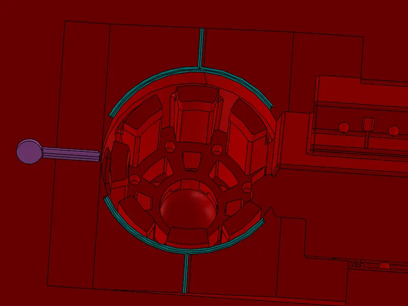
- Air Vents:- The convert entities command is used to create the sketch curve then the thin section mid plane command is used & thickness is given for extrusion.
- Then the split command is used using the consume command to get the required shape of the feature.
- The similar convert entities with 0.2 mm outside the sketch is used to get next curve for shape creation then the required is created using the sketching & extruded it for the required height.
- Then The mirror command is used to get the similar body on the other side.
- Afterwards the combine command is used to substract the body from core body for material removal from the core part.
- In this way the air vents are created for the mold.
- Cooling Channels:- The cooling channels are created using the hole wizard command in which the M10 & Ansi Metric function are implanted into it & 3 D sketch to align the holes position.
- The inlet & outlets are properly aligned to get the perfect cooling channels in the mold body.
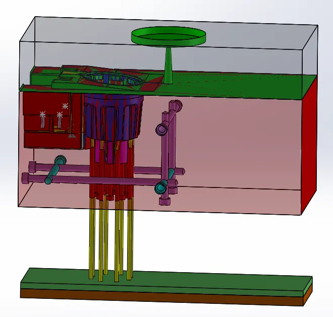
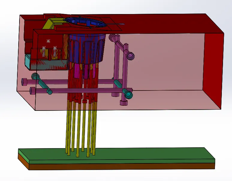
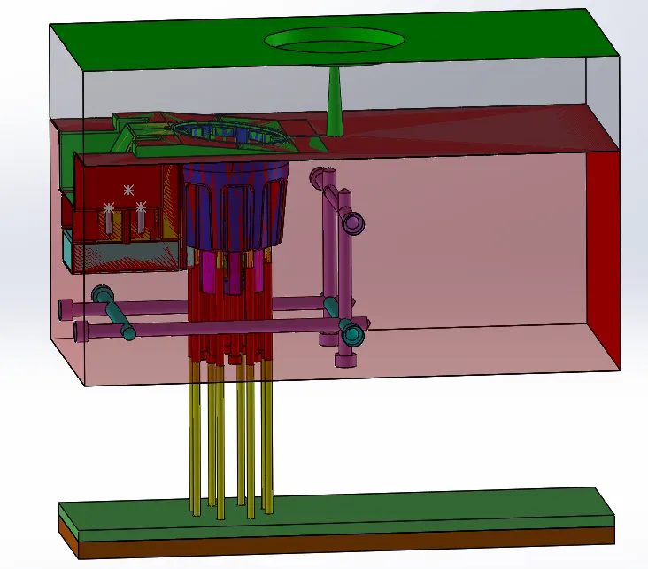
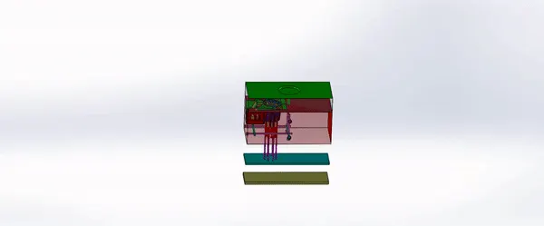
Conclusion:- In this way we have created the inserts, sliders, ejector pins, ejector plates, runner , gates, air vents, cooling channels, washers, bolts all components to proper alignments of the assembly of the mold.